Nissan Pathfinder: Interior - Removal and Installation
Front Door Finisher Nissan Pathfinder SUV
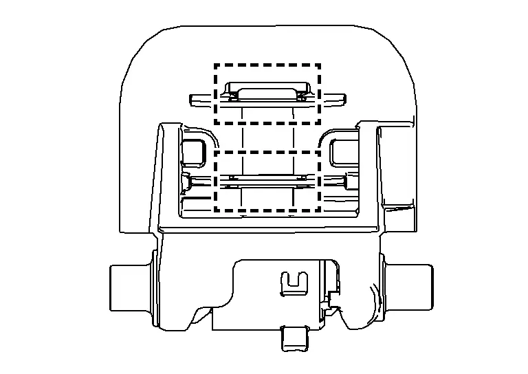
Exploded View
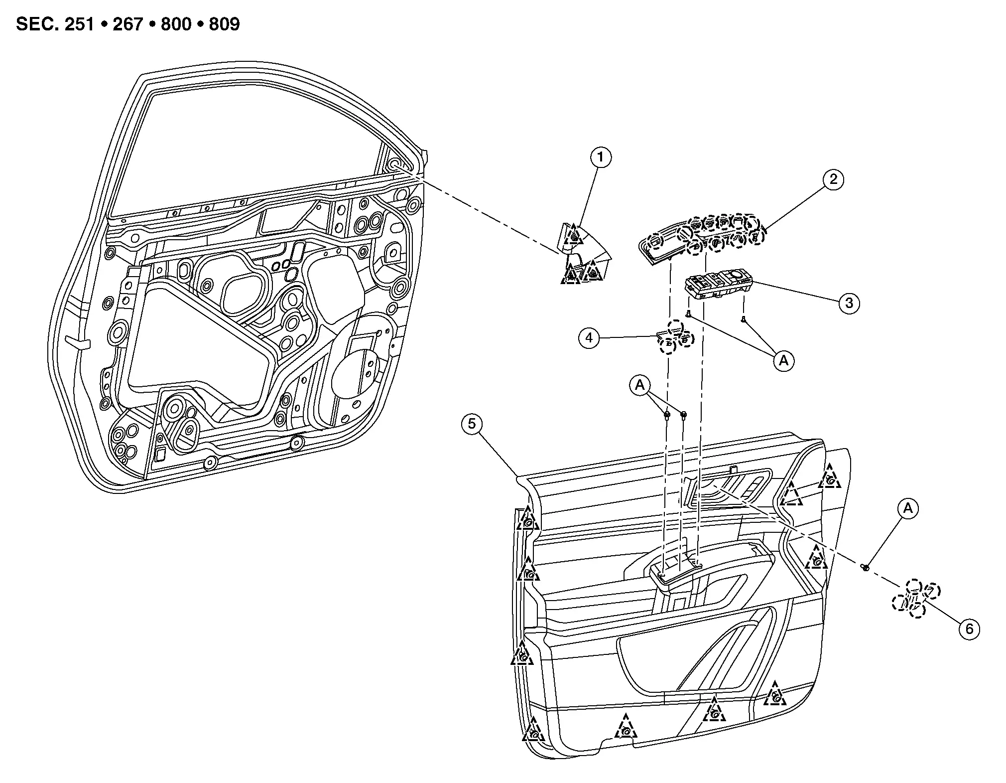
| 1. | Corner finisher | 2. | Armrest cover | 3. | Main power window and door mirror switch |
| 4. | Inside door pull handle finisher | 5. | Front door finisher | 6. | Inside door handle escutcheon |
| A. | Bolt |
 |
Pawl |
 |
Clip |
Removal and Installation
REMOVAL
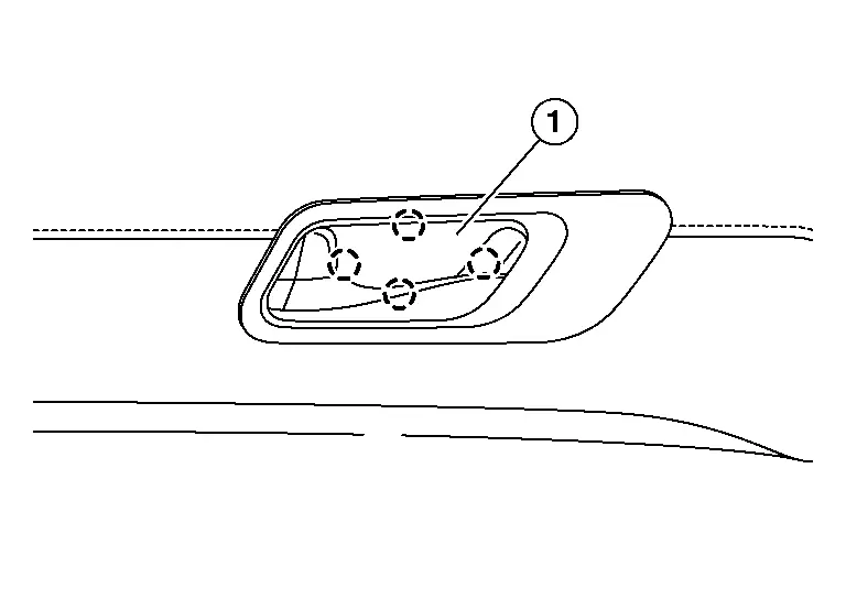
Using a suitable tool, release pawls and remove door handle escutcheon (1).
 |
: Pawl |
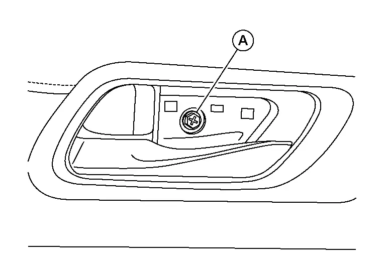
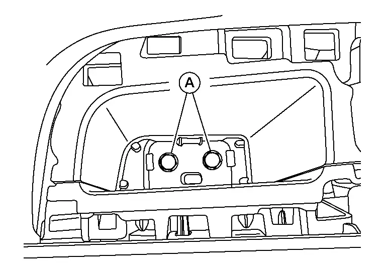
Remove bolt (A).
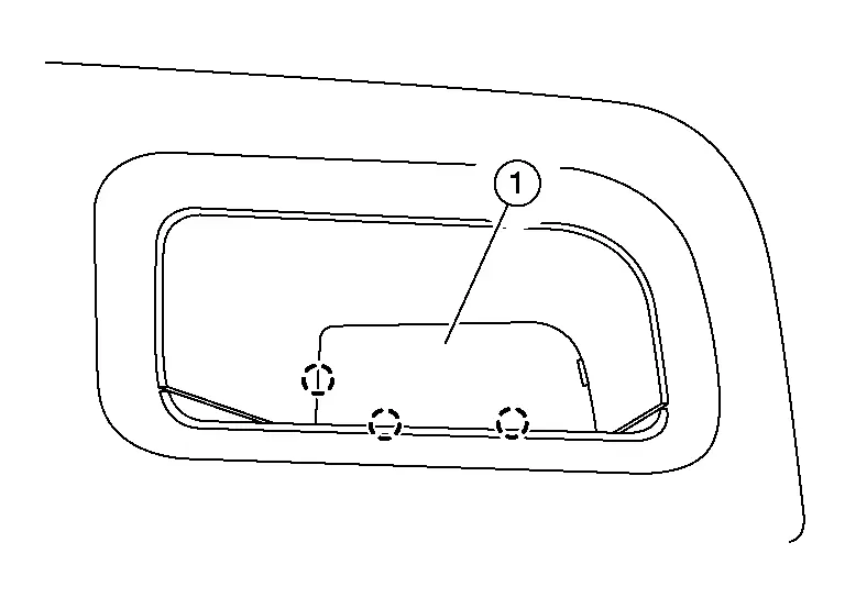
Using a suitable tool, release pawls and remove pull handle finisher (1).
 |
: Pawl |
Remove bolts (A).
Using a suitable tool, release clips. Refer to Exploded View.
Disconnect the door lock cable and inside door handle cable from inside handle. Refer to Exploded View.
Disconnect harness connectors and remove front door finisher.
INSTALLATION
Installation is in the reverse order of removal.
CAUTION:
-
Do not reuse inside door handle escutcheon. Replace with new part after removal.
-
Visually check the clips and pawls for deformation and damage during installation. Replace with new ones if necessary.
-
When installing front door finisher, check that clips and pawls are securely placed in body panel holes.
Floor Trim Nissan Pathfinder 2022
Exploded View
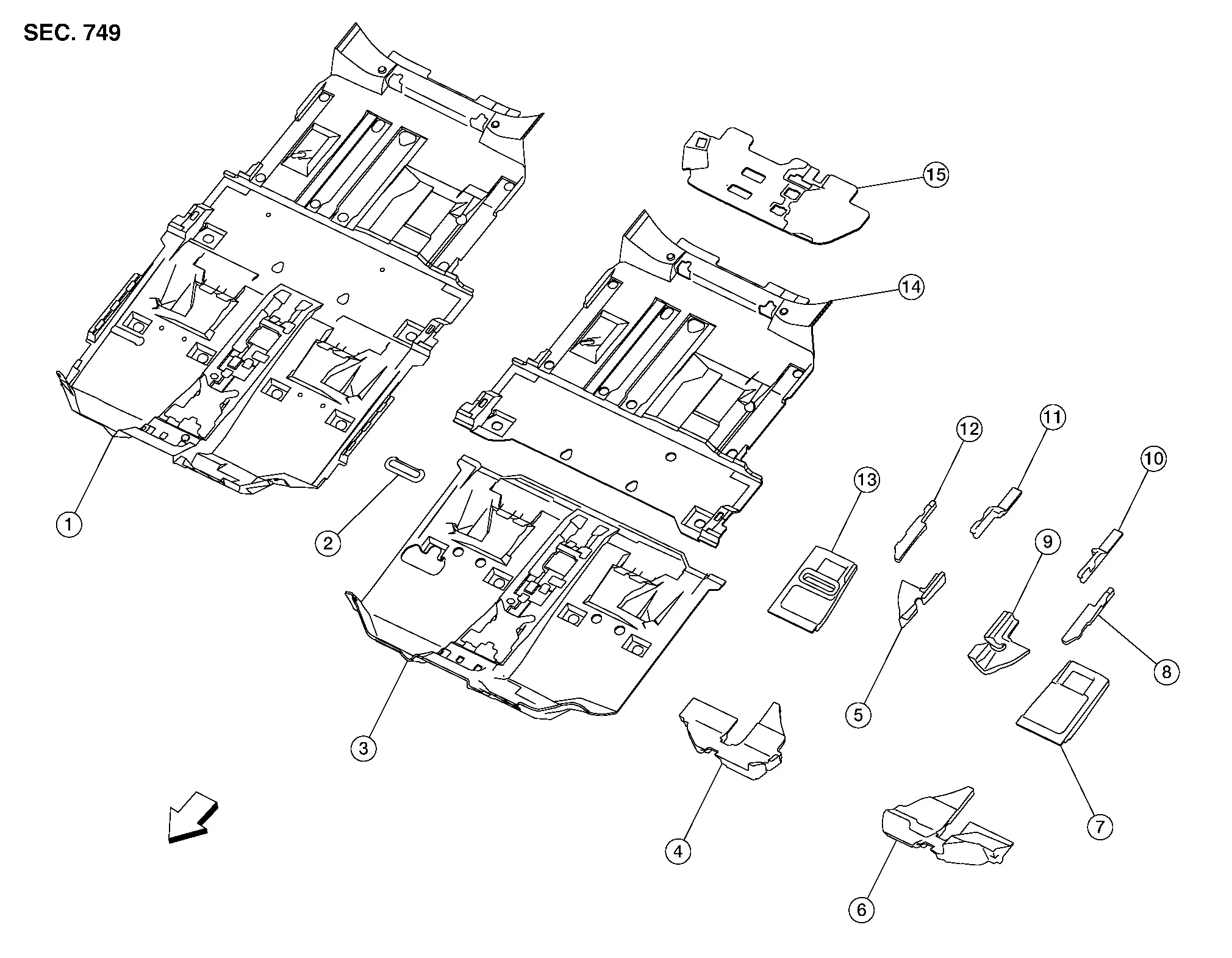
| 1. | Floor trim | 2. | Front floor trim cover | 3. | Front floor insulator |
| 4. | Front floor trim spacer (RH) | 5. | Center floor trim spacer (RH) | 6. | Front floor trim spacer (LH) |
| 7. | Side floor trirm spacer (LH) | 8. | Rear floor trim spacer outer (LH) | 9. | Center floor trim spacer (LH) |
| 10. | Rear floor trim spacer inner (LH) | 11. | Rear floor trim spacer inner (RH) | 12. | Rear floor trim spacer outer (RH) |
| 13. | Sider floor trim spacer (RH) | 14. | Rear floor insulator | 15. | Rear floor trim |
 |
Front |
Removal and Installation
FRONT FLOOR TRIM
REMOVAL
CAUTION:
Before servicing, place the ignition switch off, disconnect both battery terminals and wait at least three minutes.
Disconnect the negative battery terminal, then wait at least three minutes. Refer to Removal and Installation.
Remove the front kicking plates (LH/RH). Refer to Removal and Installation - Front Kicking Plate.
Remove the rear kicking plates (LH/RH). Refer to Removal and Installation - Rear Kicking Plate.
Remove the front seat assemblies (LH/RH). Refer to Removal and Installation.
Remove the rear heater and cooling unit. Refer to Removal and Installation.
Remove the front floor connecting duct (LH/RH). Refer to Removal and Installation - Front Floor Connecting Duct.
Remove the instrument panel lower bracket bolt and screw, then reposition bracket as necessary to remove floor trim.
Remove the center console brace bolts and remove. Refer to Exploded View.
Remove the third row seats. Refer to Removal and Installation.
Remove the second row seats. Refer to Removal and Installation.
Remove the front floor trim.
INSTALLATION
Installation is in the reverse order of removal.
REAR FLOOR TRIM
Removal
Disconnect the negative and positive battery terminals, then wait at least three minutes. Refer to Removal and Installation.
Remove the third row seat. Refer to Removal and Installation.
Remove the luggage side lower finisher (LH/RH). Refer to Removal and Installation.
Remove the rear floor trim.
Installation
Installation is in the reverse order of removal.
Headlining Nissan Pathfinder 5th Gen
Exploded View
WITH PANORAMIC MOONROOF
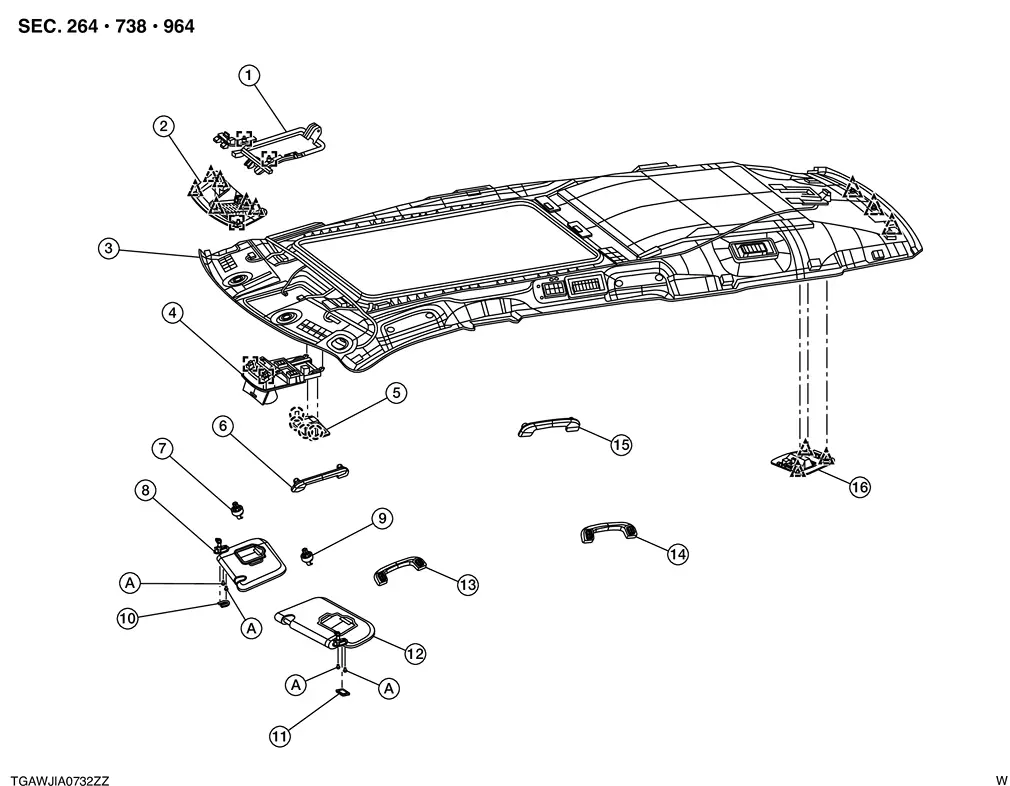
| 1. | Front room/map lamp assembly bracket | 2. | Windshield glass finisher | 3. | Headlining |
| 4. | Front room/map lamp assembly | 5. | Moonroof switch finisher | 6. | Front assist grip (RH) |
| 7. | Sun visor holder (RH) | 8. | Sun visor (RH) | 9. | Sun visor holder (LH) |
| 10. | Sun visor cover (RH) | 11. | Sun visor cover (LH) | 12. | Sun visor (LH) |
| 13. | Front assist grip (LH) | 14. | Rear assist grip (LH) | 15. | Rear assist grip (RH) |
| 16. | Seat belt retractor center finisher | A. | Bolt |
 |
Metal clip |
 |
Clip |
 |
Pawl |
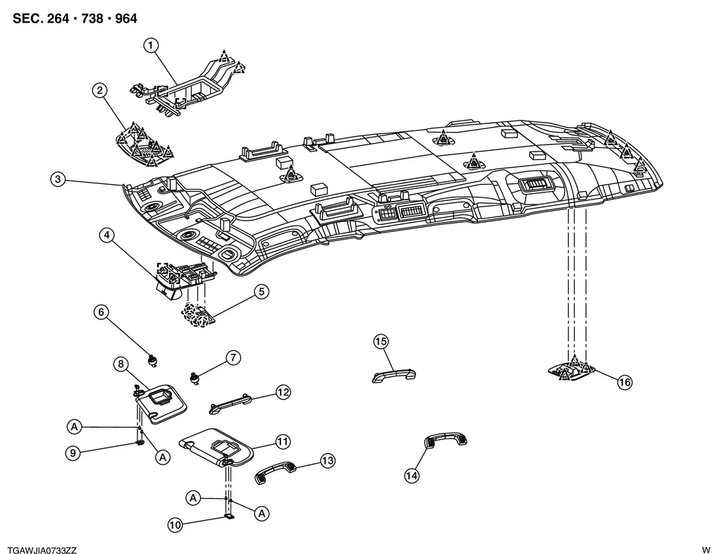
Removal and Installation
REMOVAL
WARNING:
Before servicing the SRS, place the ignition switch OFF, disconnect both battery terminals then wait at least three minutes.
Disconnect the negative and positive battery terminals, then wait at least three minutes. Refer to Exploded View.
Using a suitable tool, release sun visor caps [A (LH/RH)].
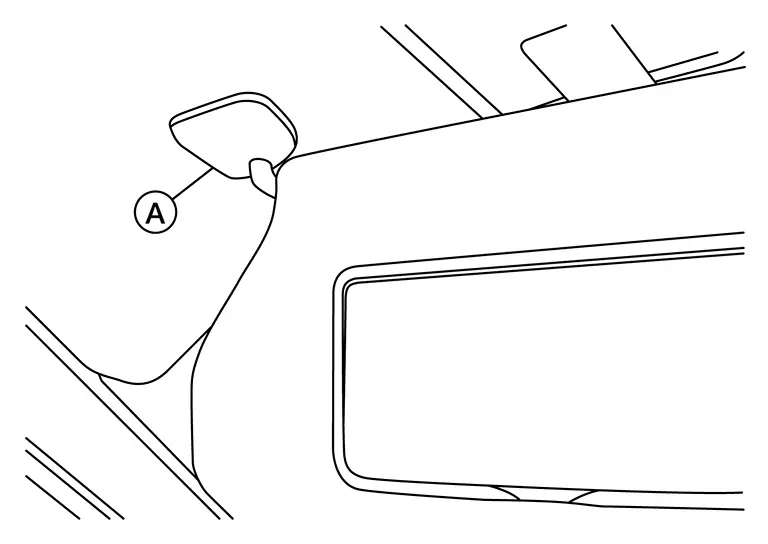
Remove sun visor screws [A (LH/RH)].
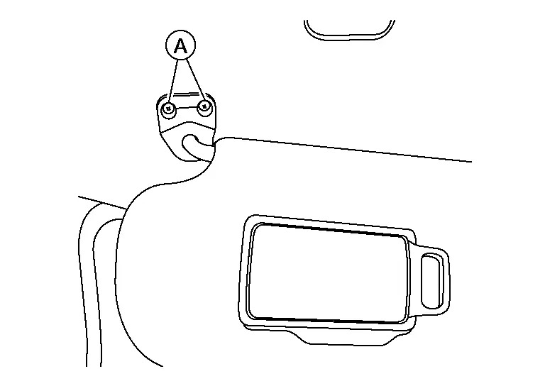
Disconnect the harness connector from the vanity mirror lamp, and remove sun visors (LH/RH).
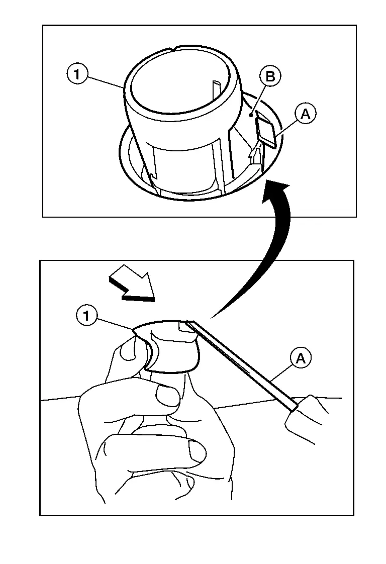
Insert a suitable tool (A) at approximately a 30 degree angle into the sun visor holder notch on the front of the sun visor holder (1). Press in to release the locking tab (B). While holding in locking tab (B), turn the sun visor holder (1) 90 degrees to release it from the headliner.
-
If the sun visor holder (1) does not fully rotate, make sure that the suitable tool (A) is pressing in on the locking tab (B) and is not positioned under locking tab (B). Reinsert the suitable tool (A) as necessary to release the locking tab (B).
-

: Front
CAUTION:
Do not force the sun visor holder when removing as the locking tab may be damaged if the suitable tool is not positioned correctly.
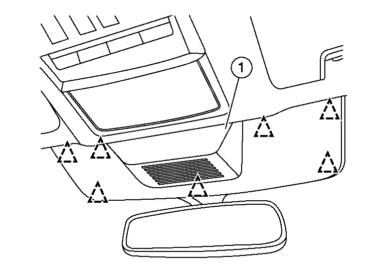
Using a suitable tool, release clips and remove the windshield glass finisher (1).
 |
: Clip |
Disconnect the harness connector (if so equipped) from the inside mirror.
Using a suitable tool, release assist grip caps (1).

Using a suitable tool, release assist grip clips.
 |
: Metal clip |
Remove all assist grips.
Remove front pillar finishers (LH/RH). Refer to Removal and Installation.
Remove front door welts (LH/RH). Refer to Removal and Installation - Front Door Welt.
Remove luggage side upper finishers (LH/RH). Refer to Removal and Installation.
Remove seat belt retractor center finisher. Refer to Exploded View.
Using a suitable tool, release headlining clips. Refer to Exploded View.
Disconnect harness connectors from headlining.
Remove headlining through the back door.
CAUTION:
-
Do not bend headlining when removing.
-
Be careful not to scratch or damage any part of the body while removing the headlining.
INSTALLATION
Installation is in the reverse order of removal.
CAUTION:
-
Do not to bend headlining when installing.
-
Install metal clips of front room/map lamp assembly and clips of the rear end of headlining for positioning.

Nissan Pathfinder (R53) 2022-2026 Service Manual
Removal and Installation
Contact Us
Nissan Pathfinder Info Center
Email: info@nipathfinder.com
Phone: +1 (800) 123-4567
Address: 123 Pathfinder Blvd, Nashville, TN 37214, USA
Working Hours: Mon–Fri, 9:00 AM – 5:00 PM (EST)
