Nissan Pathfinder: Road Wheels & Tires - Removal and Installation
Wheel and Tire Nissan Pathfinder Fifth generation
Exploded View
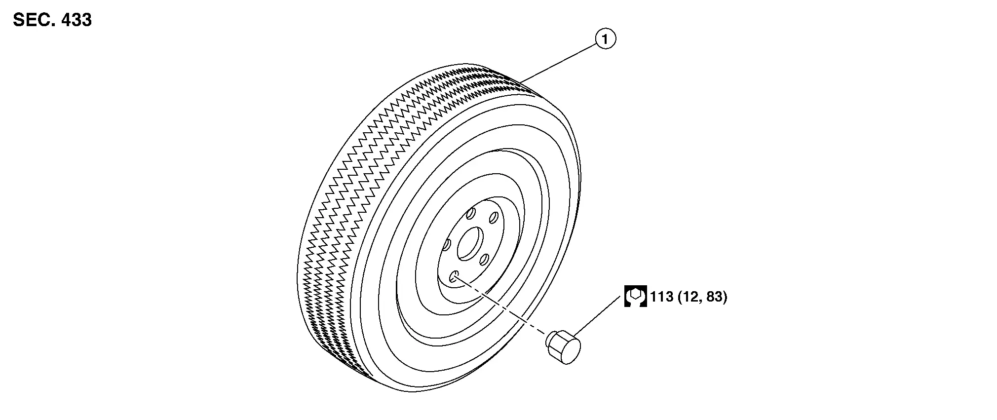
| 1. | Wheel and tire |
Removal and Installation
REMOVAL
Remove the wheel nuts using power tool. Refer to Exploded View.
Remove the wheel and tire.
INSTALLATION
Installation is in the reverse order of removal.
CAUTION:
-
When installing wheel nuts, tighten them diagonally by dividing the work two or three times in order to prevent the wheels from developing any distortion.
-
Be careful not to tighten wheel nuts to a torque exceeding the specification to prevent strain on the disc brake rotor.
-
Use Genuine NISSAN wheel nuts.
-
When replacing a tire, replacing a wheel, or performing the tire rotation, perform the "TIRE PRESSURE SENSOR ID REGISTRATION". Refer to Description.
-
If a tire was replaced, perform the "ADJUSTMENT OF STEERING ANGLE SENSOR NEUTRAL POSITION". Refer to Description.
 NOTE:
NOTE:
ID registration is unnecessary if there is no change in the position of each tire pressure sensor.
Tire Pressure Sensor Nissan Pathfinder SUV
Exploded View
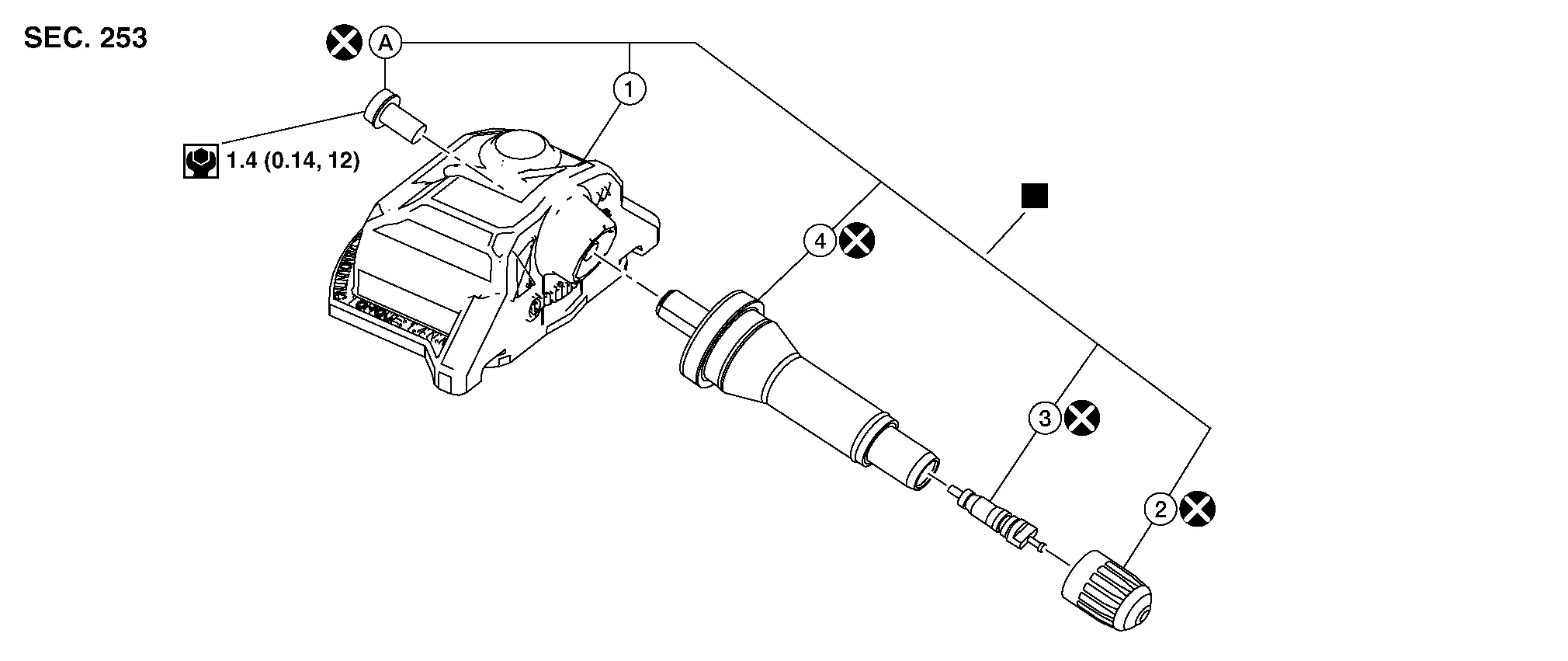
| 1. | Tire pressure sensor | 2. | Valve cap | 3. | Valve core |
| 4. | Valve | A. | Screw |
 |
: Parts that are replaced as a set when the tire is replaced. |
Removal and Installation
REMOVAL
Remove the wheel and tire using power tool. Refer to Removal and Installation.
Remove the valve cap and the valve core to deflate the tire. Refer to Exploded View.
 NOTE:
NOTE:
If the tire is to be reused, apply a matching mark on the tire in line with the position of the valve hole in the wheel for the purpose of wheel and tire balance adjustment after installation.
Lubricate the tire outside bead well with a suitable non-silicone lubricant and separate the tire outside bead from the wheel.
CAUTION:
-
Do not use silicone lubricant. Use of silicone lubricant will deteriorate the tire and wheel.
-
Do not damage the wheel.
Lubricate the tire inside bead well with a suitable non-silicone lubricant and separate the tire inside bead from the wheel.
CAUTION:
-
Do not use silicone lubricant. Use of silicone lubricant will deteriorate the tire and wheel.
-
Do not damage the wheel.
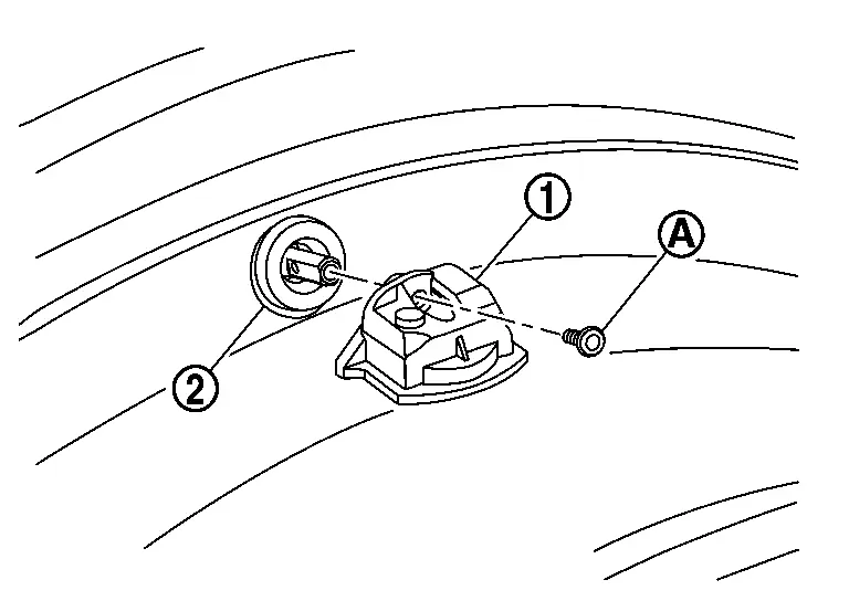
Carefully lift and set the wheel and tire onto the tire changer turntable so that the tire pressure sensor (1) is at the bottom. Position the wheel and tire so that the tire pressure sensor is 270 degrees from the mounting/dismounting head (2).

CAUTION:
Do not damage the wheel.
 NOTE:
NOTE:
To avoid damage to the Nissan Pathfinder vehicle, the tire must not slip or spin on the wheel when dismounting, or mounting a tire’s outer bead. Damage to the wheel or the tire pressure sensor could result.
Remove the tire from the wheel.
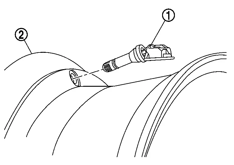
Remove the screw (A) and the tire pressure sensor (1) from the valve (2).
CAUTION:
-
Do not drop or strike the tire pressure sensor. Replace the tire pressure sensor if it has been dropped from higher than one meter.
-
Do not reuse the screw.
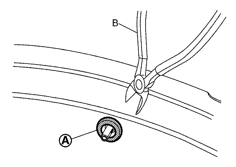
Cut the inner end (A) of the valve using a suitable tool (B).
CAUTION:
-
Do not drop or strike the tire pressure sensor. Replace the tire pressure sensor if it has been dropped from higher than one meter.
-
Do not reuse the valve.
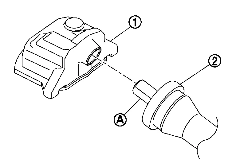
Remove the valve (2) from the wheel (1) using Tool (A).
| Tool (A) number | : NI-51980 |
CAUTION:
-
Do not damage the wheel.
-
Pull the valve straight through the rim hole perpendicularly to the rim hole.
INSTALLATION
CAUTION:
Do not loosen the screw if the tire pressure sensor and the valve are being replaced as an assembly.
Clean the valve hole in the wheel.
CAUTION:
Make sure there are no burrs, foreign substances, or indications of damage to the wheel.
When reusing the tire pressure sensor, install the tire pressure sensor to the valve using the following procedure:Install the tire pressure sensor (1) to the roll pin (A) of the valve (2).
CAUTION:
-
Do not drop or strike the tire pressure sensor. Replace the tire pressure sensor if it has been dropped from higher than one meter.
-
Do not reuse the valve.
CAUTION:
Do not reuse the screw.
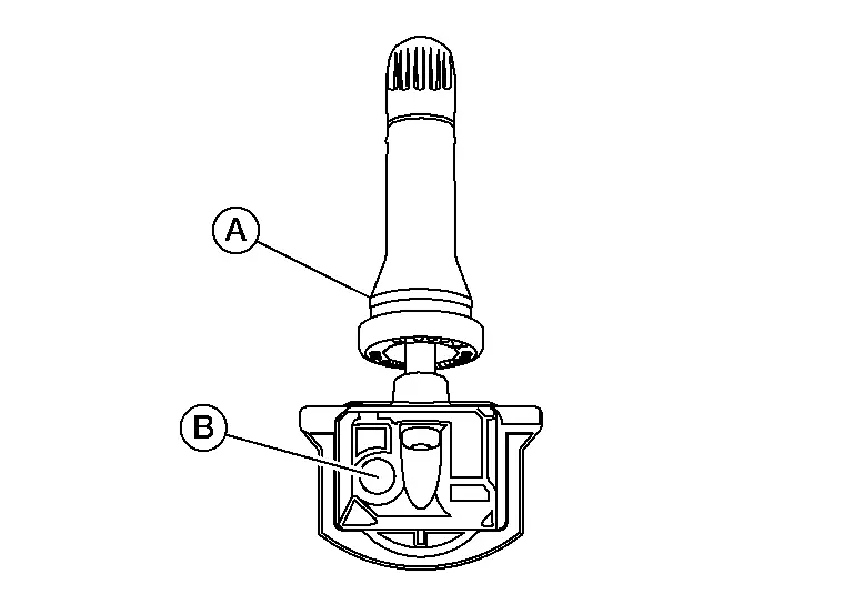
Apply a suitable non-silicone lubricant to the surface of the valve (A) that touches the wheel and to the valve hole in the wheel.
CAUTION:
-
Do not use silicone lubricant. Use of silicone lubricant will deteriorate the tire and wheel.
-
Do not allow lubricant to contact the air pressure detection hole (B).
Position the tire pressure sensor assembly (1) on the wheel (2).
CAUTION:
-
Do not damage the tire pressure sensor.
-
Do not allow lubricant to contact the air pressure detection hole.
-
The tire pressure sensor must be oriented tangentially to the rim of the wheel.
Install the tire pressure sensor assembly (2) to the wheel (1) using Tool (A).

| Tool (A) number | : NI-51980 |
CAUTION:
-
Do not damage the wheel.
-
Install the valve all the way to the wheel.
-
Make sure the valve seats properly in the valve hole in the wheel.
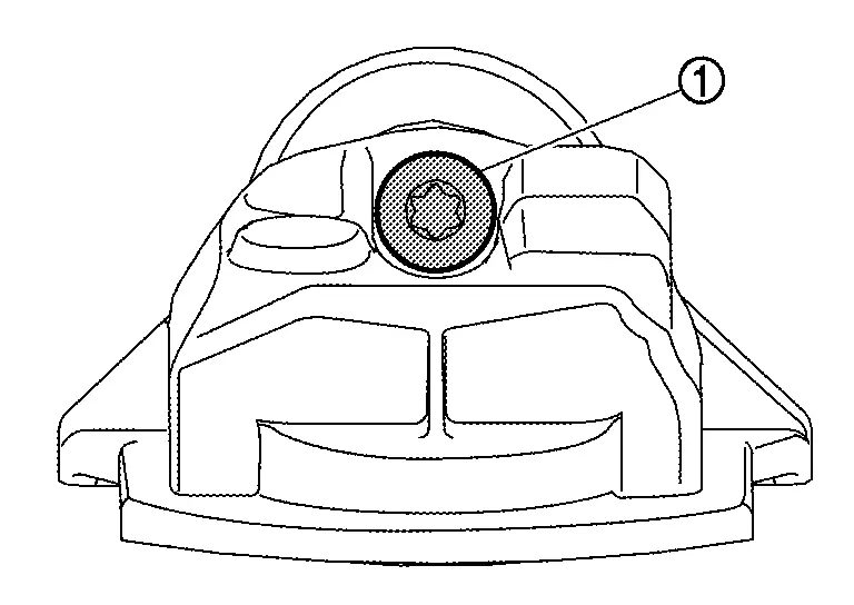
Check the tire pressure sensor assembly (1) position. The tire pressure sensor assembly must be installed to the wheel (2) as shown.
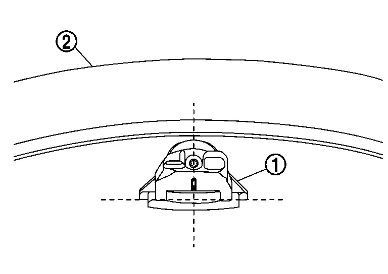
CAUTION:
-
Do not damage the wheel.
-
Do not damage the tire pressure sensor.
-
The tire pressure sensor must be oriented tangentially to the rim of the wheel.
-
If the tire pressure sensor unit position is not correct, rotate the tire pressure sensor unit to the correct position using Tool.
Apply a suitable non-silicone lubricant to the tire inside bead.
CAUTION:
-
Do not use silicone lubricant. Use of silicone lubricant will deteriorate the tire and wheel.
-
Do not allow lubricant to contact the air pressure detection hole.
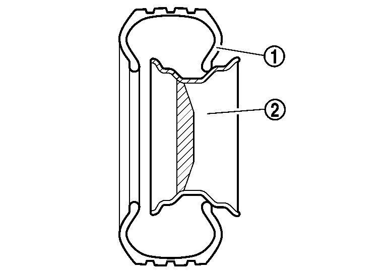
Install the tire inside bead (1) onto the wheel (2) in the position shown.
CAUTION:
-
Do not damage the wheel or the tire pressure sensor.
-
Do not allow the tire beads to make contact with the tire pressure sensor.
Place the wheel on the turntable of the tire machine. Make sure that the tire pressure sensor (1) is 270 degrees from the mounting/dismounting head (2).
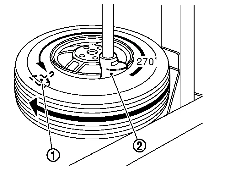
CAUTION:
Do not touch the tire pressure sensor with the mounting head.
Apply a suitable non-silicone lubricant to the tire outside bead.
CAUTION:
-
Do not use silicone lubricant. Use of silicone lubricant will deteriorate the tire and wheel.
-
Do not allow lubricant to make contact with the tire pressure sensor.
Install the tire outside bead onto the wheel as normal.
 NOTE:
NOTE:
-
If the tire is being reused, align the matching mark applied on the tire with the position of the valve hole in the wheel for the purpose of wheel and tire balance adjustment after installation.
-
To avoid damage to the Nissan Pathfinder vehicle, the tire must not slip or spin on the wheel when dismounting, or mounting a tire’s outer bead. Damage to the wheel or the tire pressure sensor could result.
Install the valve core.
CAUTION:
Do not reuse the valve core.
Inflate the tire. Refer to Tire Air Pressure.
Install the valve cap.
CAUTION:
Do not reuse the valve cap.
Balance the wheel and tire. Refer to Adjustment.
Install the wheel and tire in the appropriate position on the Nissan Pathfinder vehicle. Refer to Removal and Installation.
CAUTION:
-
When replacing the tire pressure sensor, perform the "TIRE PRESSURE SENSOR ID REGISTRATION". Refer to Description.
-
If a tire was replaced, perform the "ADJUSTMENT OF STEERING ANGLE SENSOR NEUTRAL POSITION". Refer to Description.
Tire Pressure Receiver Nissan Pathfinder Fifth generation
Removal and Installation
The tire pressure receiver is integrated in the BCM (Body Control Module). Refer to Removal and Installation.

Nissan Pathfinder (R53) 2022-2026 Service Manual
Removal and Installation
Contact Us
Nissan Pathfinder Info Center
Email: info@nipathfinder.com
Phone: +1 (800) 123-4567
Address: 123 Pathfinder Blvd, Nashville, TN 37214, USA
Working Hours: Mon–Fri, 9:00 AM – 5:00 PM (EST)
