Nissan Pathfinder: Rear Suspension - Removal and Installation
- Rear Lower Link Coil Spring
- Rear Shock Absorber
- Radius Rod
- Front Lower Link
- Rear Stabilizer
- Rear Suspension Arm
Rear Lower Link Coil Spring Nissan Pathfinder
Exploded View
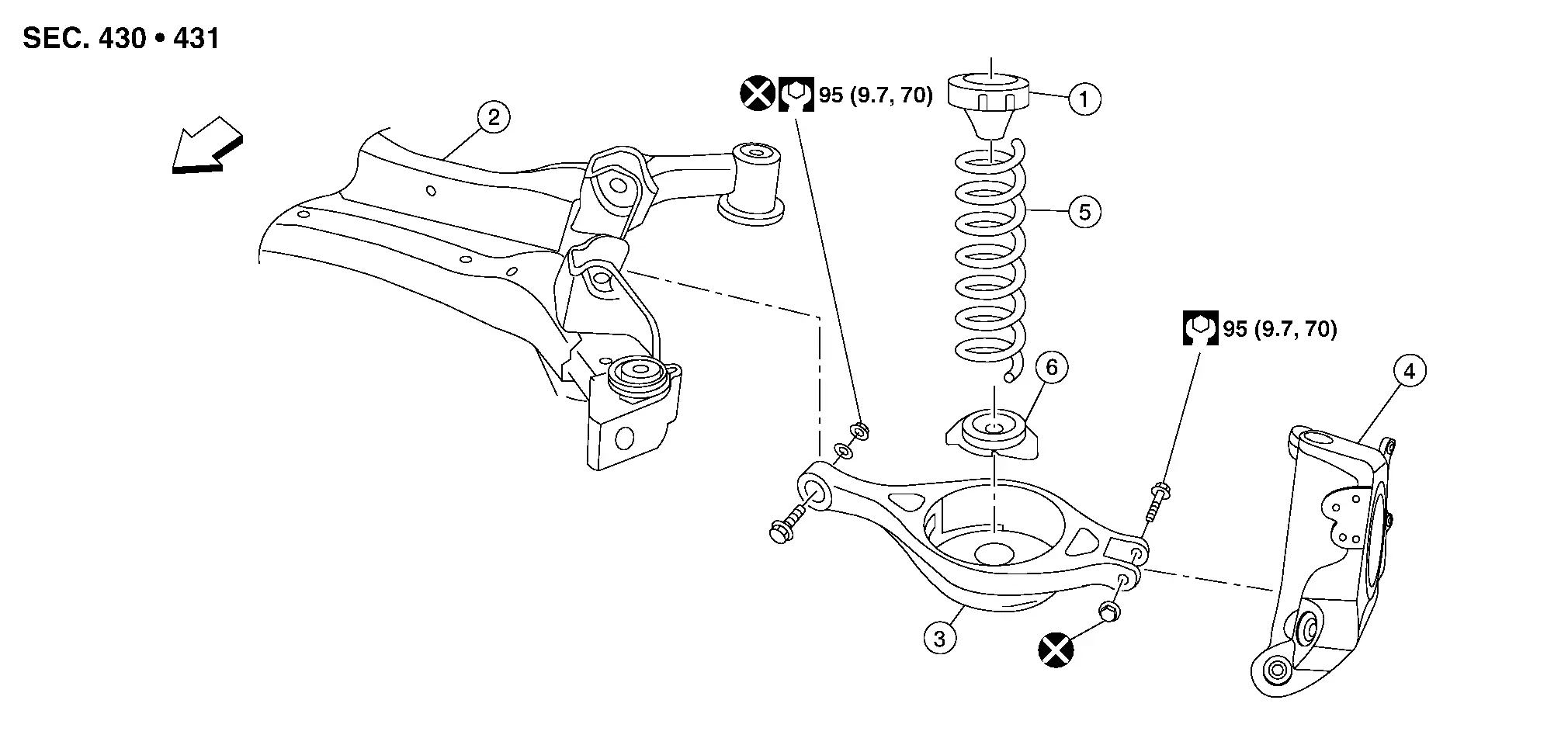
| 1. | Upper seat | 2. | Rear suspension member | 3. | Rear lower link |
| 4. | Rear knuckle | 5. | Coil spring | 6. | Lower seat |
 |
Front |
Removal and Installation
REMOVAL
Remove the rear wheels and tires using power tool. Refer to Removal and Installation.
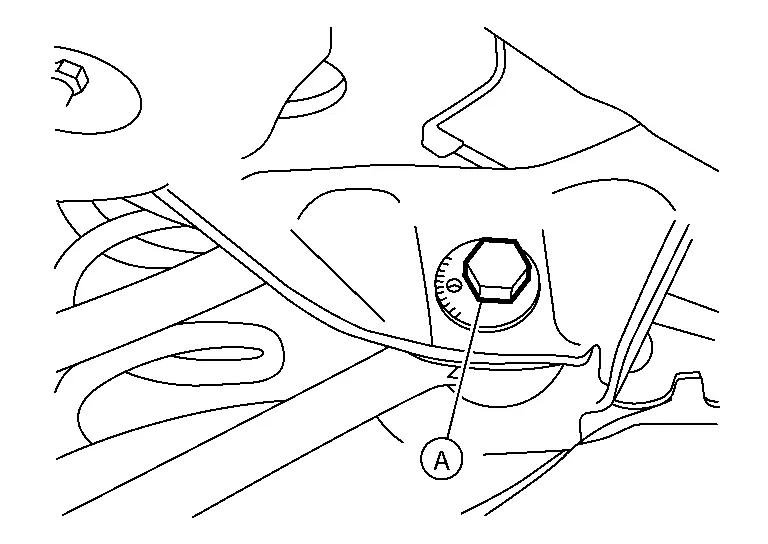
Put alignment marks on the adjusting bolt (A) and on the rear lower link (B).
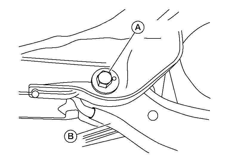
Loosen the rear lower link adjusting bolt on the rear suspension member.
Support the rear lower link with a suitable jack.
WARNING:
Place a suitable jack under the outer end of the rear lower link.
CAUTION:
Do not damage the rear lower link with the suitable jack.
Support the rear knuckle with a suitable jack.
WARNING:
Place a suitable jack under the center of the rear knuckle.
CAUTION:
Do not damage the rear knuckle with the suitable jack.
Remove the rear lower link nut and bolt from the rear knuckle using power tool.
CAUTION:
Do not reuse lower link nut.
Slowly lower the suitable jack supporting the rear lower link. Remove the upper seat, the coil spring, and the lower seat from the rear lower link.
Remove the rear lower link nut and bolt from the rear suspension member using power tool.
CAUTION:
Do not reuse lower link nut.
Remove the rear lower link.
INSTALLATION
Installation is in the reverse order of removal.
CAUTION:
Do not reuse rear lower link nuts.
-
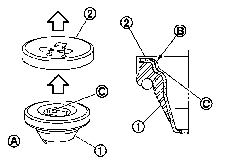
Make sure that the upper seat is attached as shown.
CAUTION:
-
Keep the upper seat (1) in place during coil spring installation. The protrusion (A) on the upper seat faces the outside of the Nissan Pathfinder vehicle.
-
Align the tabs (C) to the upper seat openings and securely fit the bracket (2) to the tabs (B).

: Body -
-
Match up the lower seat indentions and the rear lower link grooves.
-
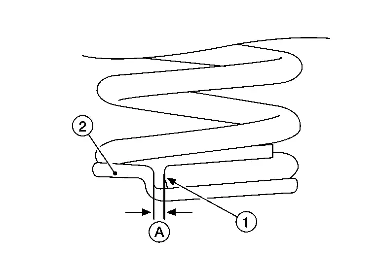
When installing the coil spring (1), position the coil spring as shown.
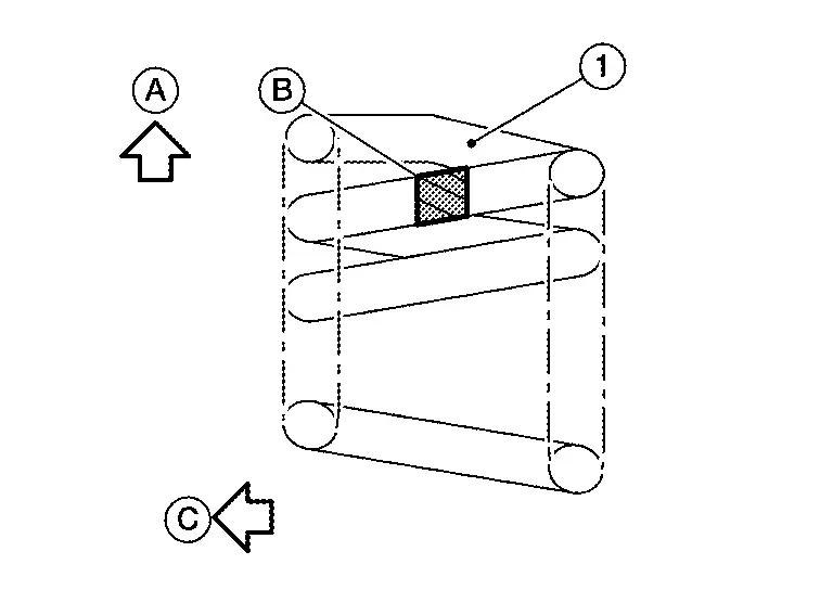
(A): Nissan Pathfinder Vehicle upper side
(B): 1 paint mark
(C): Vehicle inside
CAUTION:
Position the coil spring with the 2 paint marks 3.5 turns from the bottom.
-
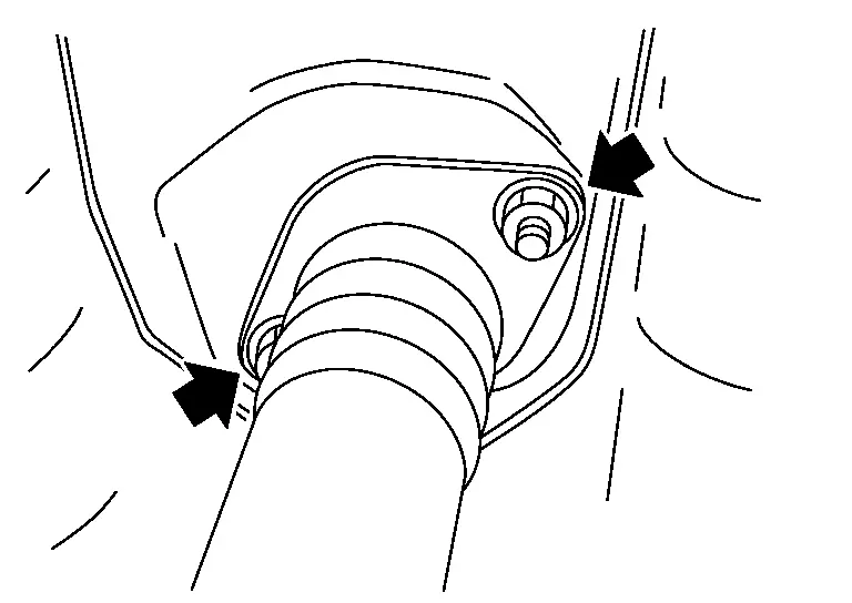
Install the coil spring by aligning the lower end of the coil spring (1) to the bump on the lower spring seat (2).
(A) : Maximum gap 5 mm (0.20 in) -
Perform the final tightening of the parts under unladen conditions with the tires on the ground.
CAUTION:
Do not reuse lower link nut.
-
Check the wheel alignment. Refer to Inspection and Adjustment.
-
Adjust the neutral position of the steering angle sensor. Refer to Description.
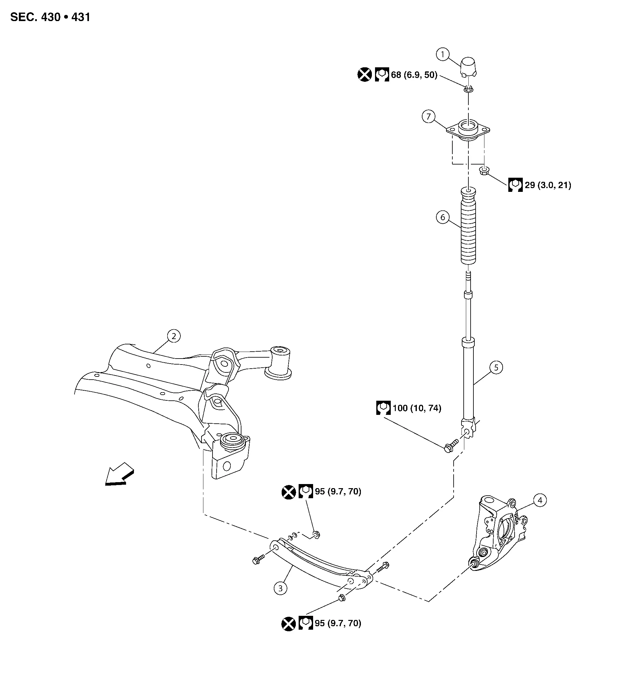
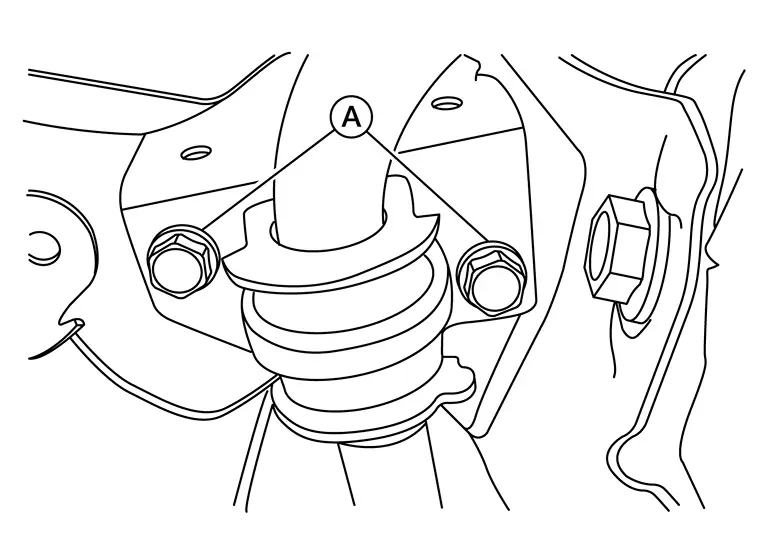
Rear Shock Absorber Nissan Pathfinder
Exploded View
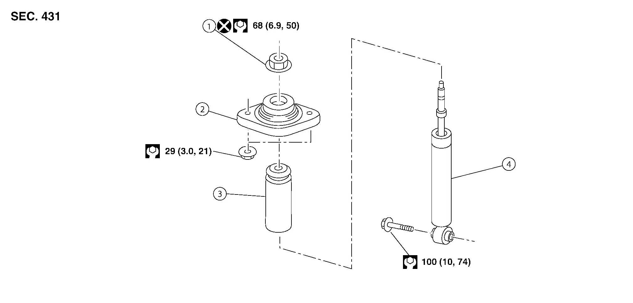
| 1. | Piston rod lock nut | 2. | Shock absorber insulator | 3. | Bound bumper |
| 4. | Rear shock absorber |
Removal and Installation
REMOVAL
Remove the rear wheels and tires using power tool. Refer to Removal and Installation.
Set a suitable jack under the rear lower link to relieve the coil spring tension.
WARNING:
Place a suitable jack under the outer end of the rear lower link.
CAUTION:
Do not damage the rear lower link with the suitable jack.
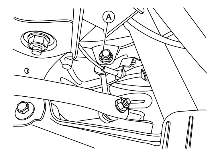
Remove the lower rear shock absorber bolt (A) with power tool.
Gradually lower the suitable jack to separate the rear shock absorber from the rear lower link.
Remove the rear shock absorber nuts (
 ).
).
Remove the rear shock absorber.
INSTALLATION
Installation is in the reverse order of removal.
-
Perform the final tightening of the parts under unladen conditions with the tires on the ground.
Disposal
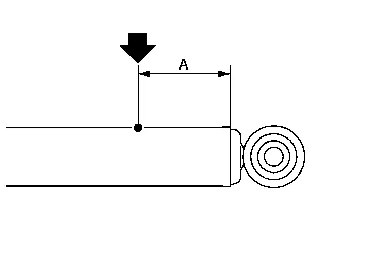
Set the shock absorber horizontally with the piston rod fully extended.
Drill a 2 – 3 mm (0.08 – 0.12 in) hole at the position (
 ) as shown to release gas gradually.
CAUTION:
-
Wear eye protection (safety glasses).
-
Wear gloves.
-
Be careful with metal chips or oil blown out by the compressed gas.
 NOTE:
NOTE:
-
Drill vertically in this direction (
 ) directly into the outer tube avoiding brackets.
 -
The gas is clear, colorless, odorless, and harmless.
| (A) | : 20 – 30 mm (0.79 – 1.18 in) |
Position the drilled hole downward and drain the oil by moving the piston rod several times.
CAUTION:
Dispose of drained oil according to the law and local regulations.
Radius Rod Nissan Pathfinder R53
Exploded View

| 1. | Rear suspension member | 2. | Radius rod | 3. | Rear knuckle |
 |
Front |
Removal and Installation
REMOVAL
Remove the rear wheels and tires using power tool. Refer to Removal and Installation.
Remove the radius rod bolt and nut from the rear knuckle using power tool.
CAUTION:
Do not reuse the radius rod nut.
Remove the radius rod bolt from the rear suspension member using power tool.
Remove the radius rod.
INSTALLATION
Installation is in the reverse order of removal.
CAUTION:
Do not reuse the radius rod nut.
Front Lower Link Nissan Pathfinder 2022
Exploded View
| 1. | Cap | 2. | Rear suspension member | 3. | Front lower link |
| 4. | Rear knuckle | 5. | Rear shock absorber | 6. | Bound bumper |
| 7. | Shock absorber insulator |
 |
Front |
Removal and Installation
REMOVAL
Remove the rear wheels and tires using power tool. Refer to Removal and Installation.
Support the rear lower link with a suitable jack.
WARNING:
Place a suitable jack under the outer end of the rear lower link.
CAUTION:
Do not damage the rear lower link with the suitable jack.
Support the rear knuckle with a suitable jack.
WARNING:
Place a suitable jack under the center of the rear knuckle.
CAUTION:
Do not damage the rear knuckle with the suitable jack.
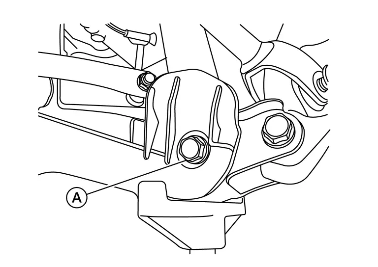
Index mark the adjusting bolt (A) to the rear suspension member.
Remove the lower shock absorber bolt using power tool. Refer to Exploded View.
Partially remove stabilizer bar mounting brackets. Refer to Exploded View.
Remove the front lower link bolt and nut from the rear suspension member using power tool.
CAUTION:
Do not reuse the front lower link nuts.
Remove the front lower link bolt and nut from the rear knuckle using power tool.
CAUTION:
Do not reuse the front lower link nuts.
Remove the front lower link cover.
Remove the front lower link.
INSTALLATION
Installation is in the reverse order of removal.
CAUTION:
Do not reuse the front lower link nuts.
-
Perform the final tightening of the parts under unladen conditions with the tires on the ground.
-
Check the wheel alignment. Refer to Inspection and Adjustment.
-
Adjust the neutral position of the steering angle sensor. Refer to Description.
Rear Stabilizer Nissan Pathfinder 5th Gen
Exploded View
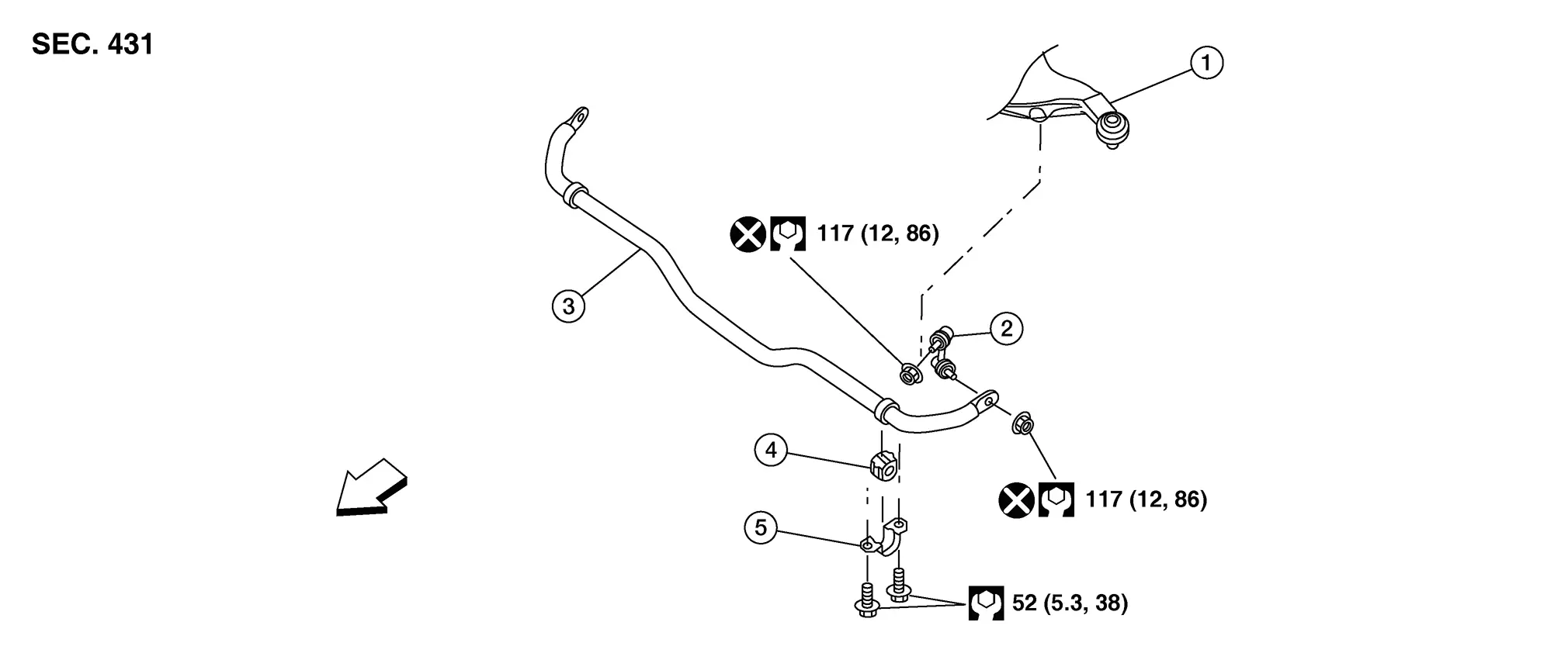
| 1. | Rear suspension arm | 2. | Connecting rod (LH) | 3. | Stabilizer bar |
| 4. | Stabilizer bar bushing | 5. | Stabilizer bar clamp |
 |
Front |
Removal and Installation
REMOVAL
Apply matching marks to the rear suspension arms, the connecting rods, and the stabilizer shaft to identify the installation position.
Remove both upper connecting rod nuts (A). Disconnect both connecting rods from the rear suspension arms.
CAUTION:
Do not reuse connecting rod nuts.
Remove the 4 stabilizer clamp bolts (A) using power tool.
Remove the stabilizer clamps.
Remove the stabilizer bar bushings.
Remove the stabilizer bar.
Remove both lower connecting rod nuts. Disconnect both connecting rods from the stabilizer bar.
INSTALLATION
Installation is in the reverse order of removal.
-
Position the stabilizer bar bushings with the slit facing the front of the vehicle.
-
Align the matching marks when installing.
-
Tighten the connecting rod nut to the specified torque while holding the hexagonal part of the connecting rod stud.
CAUTION:
Do not reuse connecting rod nuts.
Rear Suspension Arm Nissan Pathfinder 5th Gen
Exploded View
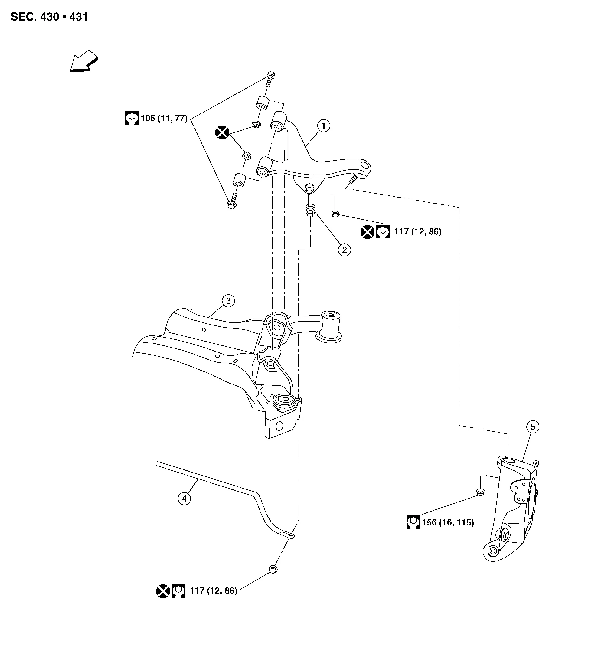
| 1. | Rear suspension arm | 2. | Connecting rod (LH) | 3. | Rear suspension member |
| 4. | Stabilizer bar | 5. | Rear knuckle |
 |
Front |
Removal and Installation
REMOVAL
Remove rear suspension member. Refer to Removal and Installation.
Remove the suspension arm bolt and nut from the rear knuckle using power tool. Disconnect the suspension arm from the rear knuckle.
Remove the suspension arm bolts and nuts from the rear suspension member using power tool.
CAUTION:
Do not reuse the rear suspension arm nuts at the rear suspension member.
Remove the suspension arm.
INSTALLATION
Installation is in the reverse order of removal.
CAUTION:
Do not reuse the rear suspension arm nuts at the rear suspension member.
-
Do not reuse connecting rod nut.
-
Perform the final tightening of the parts under unladen conditions with tires on the ground.
-
Check the wheel sensor harness for proper connection. Refer to Exploded View.
-
Check the wheel alignment. Refer to Inspection and Adjustment.
-
Adjust the neutral position of the steering angle sensor. Refer to Description.

Nissan Pathfinder (R53) 2022-2026 Service Manual
Removal and Installation
- Rear Lower Link Coil Spring
- Rear Shock Absorber
- Radius Rod
- Front Lower Link
- Rear Stabilizer
- Rear Suspension Arm
Contact Us
Nissan Pathfinder Info Center
Email: info@nipathfinder.com
Phone: +1 (800) 123-4567
Address: 123 Pathfinder Blvd, Nashville, TN 37214, USA
Working Hours: Mon–Fri, 9:00 AM – 5:00 PM (EST)
