Nissan Pathfinder: Rear Axle - Removal and Installation
Rear Wheel Hub Nissan Pathfinder
Exploded View
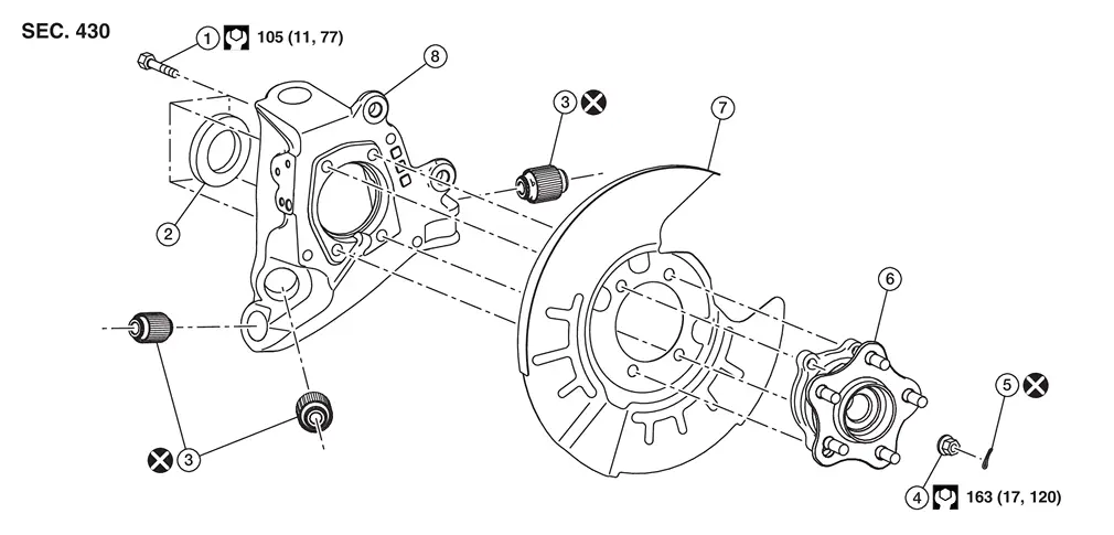
| 1. | Wheel hub bearing bolt | 2. | Dust shield | 3. | Bushings |
| 4. | Wheel hub lock nut (4WD) | 5. | Cotter pin (4WD) | 6. | Wheel hub and bearing |
| 7. | Back plate | 8. | Rear knuckle |
Removal and Installation
REMOVAL
Remove the rear wheel and tire using power tool. Refer to Removal and Installation.
Remove the brake caliper torque member bolts, leaving the brake hose attached. Position the caliper aside with wire. Refer to Removal and Installation.
CAUTION:
Do not depress the brake pedal while the caliper assembly is removed.
Put alignment marks on the disc brake rotor and on the wheel hub and bearing. Remove the disc brake rotor.
CAUTION:
Do not drop the disc brake rotor.
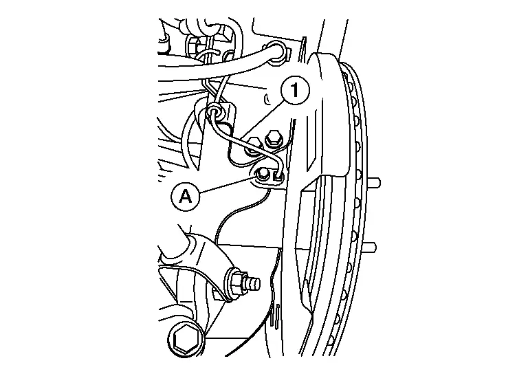
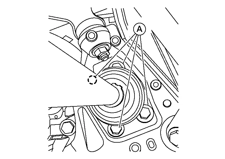
Remove the wheel sensor (1) from the knuckle (A) and place aside. Refer to Exploded View.
For 4WD Nissan Pathfinder vehicles, remove the cotter pin.
For 4WD vehicles, loosen, but do not remove, the wheel hub lock nut from the drive shaft using power tool.
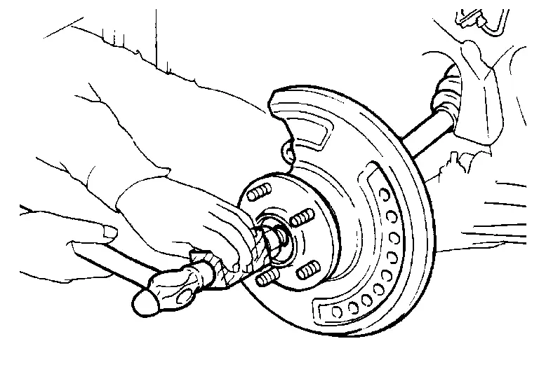
For 4WD Nissan Pathfinder vehicles, use a piece of wood and a hammer, tap on the wheel hub lock nut to disengage the drive shaft from the wheel hub and bearing.
CAUTION:
-
Do not place the drive shaft joint at an extreme angle. Do not to overextend the slide joint.
-
Do not allow the drive shaft to hang without support.
 NOTE:
NOTE:
Use a suitable puller if the drive shaft cannot be separated from the wheel hub and bearing.
For 4WD Nissan Pathfinder vehicles, remove the wheel hub lock nut.
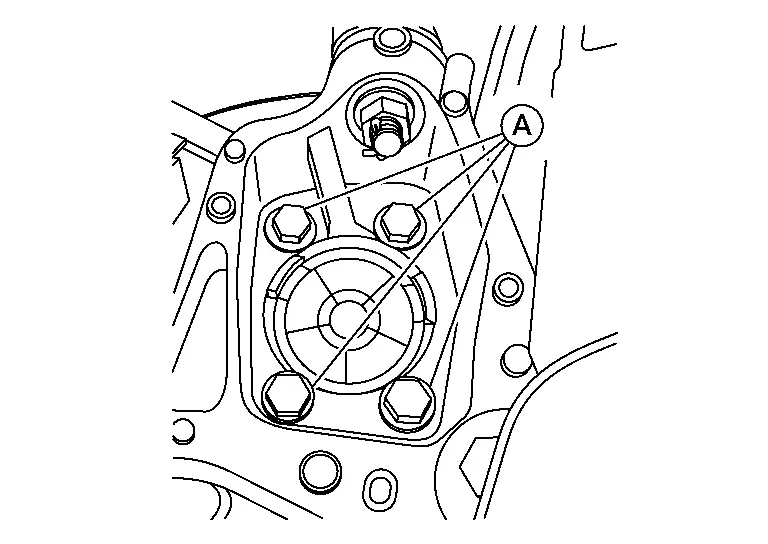
Remove the wheel hub and bearing bolts (A).
-
2WD
-
4WD
Remove the wheel hub and bearing.
Remove the dust shield.
INSTALLATION
Installation is in the reverse order of removal.
CAUTION:
-
Do not reuse the cotter pin.
-
Do not use a power tool to tighten the wheel hub lock nut.
-
Clean the mating surface of the wheel hub lock nut and the wheel hub and bearing.
-
Clean the mating surface of the drive shaft and the wheel hub and bearing.
-
Align the marks on the disc brake rotor and on the wheel hub and bearing.
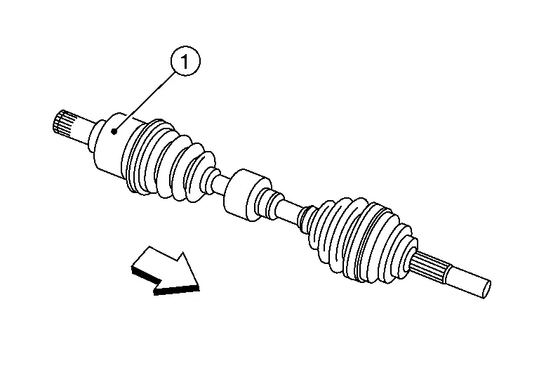
Rear Drive Shaft Nissan Pathfinder 2022
Exploded View
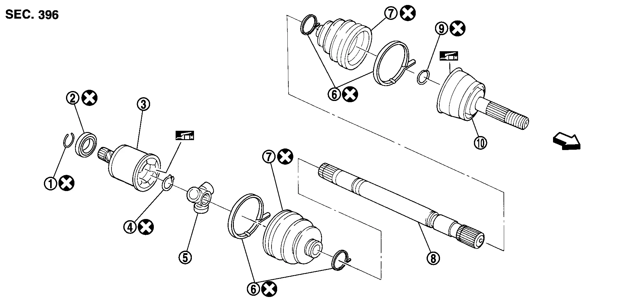
| 1. | Circular clip | 2. | Dust shield | 3. | Housing |
| 4. | Snap ring | 5. | Spider assembly | 6. | Boot band |
| 7. | Boot | 8. | Shaft | 9. | Circular clip |
| 10. | Joint sub-assembly |
 |
Wheel side |
Removal and Installation
REMOVAL
Remove rear final drive assembly. Refer to Removal and Installation.
Remove the rear drive shaft from the final drive assembly.
Remove the side oil seal. Refer to Removal and Installation.
CAUTION:
Do not reuse the side oil seal.
INSPECTION AFTER REMOVAL
-
Move joint sub-assembly up/down, left/right and in axial direction. Check for any rough movement or significant looseness.
-
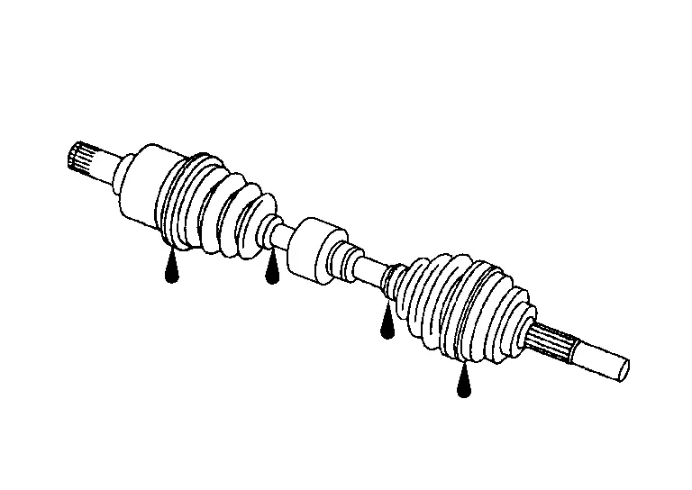
Check boots for cracks, grease leakage or other damage.
-
If damaged, disassemble drive shaft to verify damage and repair or replace as necessary.
INSTALLATION
Installation is in the reverse order of removal.
CAUTION:
-
Do not reuse the side oil seal.
-
Do not reuse the cotter pin.
-
Do not use a power tool to tighten the wheel hub lock nut.
-
In order to prevent damage to the side oil seal, place Tool (A) onto oil seal, as shown, before inserting the drive shaft.
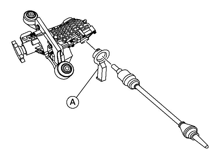
Tool number (A) : KV38107900 (NI-52469-1)
WARNING:
Ensure that circular clip is properly engaged, otherwise the joint sub-assembly could pull away from transaxle during Nissan Pathfinder vehicle operation resulting in loss of drive force and possible drive shaft damage, which may cause a crash and serious injury or damage the drive shaft.
-
To ensure the circular clip is properly engaged, grasp the housing (1) and pull back and forth in axial direction while listening for clicking sounds.
-
Pull the joint sub-assembly in the axial direction away from transaxle assembly (
 ). Confirm that the joint sub assembly cannot be pulled out.
 -
Slide rear drive shaft into the slide joint and tap with a hammer to install securely.
-
Clean the mating surface of the wheel hub lock nut and the wheel hub and bearing.
-
Clean the mating surface of the drive shaft and the wheel hub and bearing.
-
Align the marks on the disc brake rotor and on the wheel hub and bearing.

Nissan Pathfinder (R53) 2022-2026 Service Manual
Removal and Installation
Contact Us
Nissan Pathfinder Info Center
Email: info@nipathfinder.com
Phone: +1 (800) 123-4567
Address: 123 Pathfinder Blvd, Nashville, TN 37214, USA
Working Hours: Mon–Fri, 9:00 AM – 5:00 PM (EST)
