Nissan Pathfinder: Front Axle - Removal and Installation
Front Wheel Hub Nissan Pathfinder 2026
Exploded View
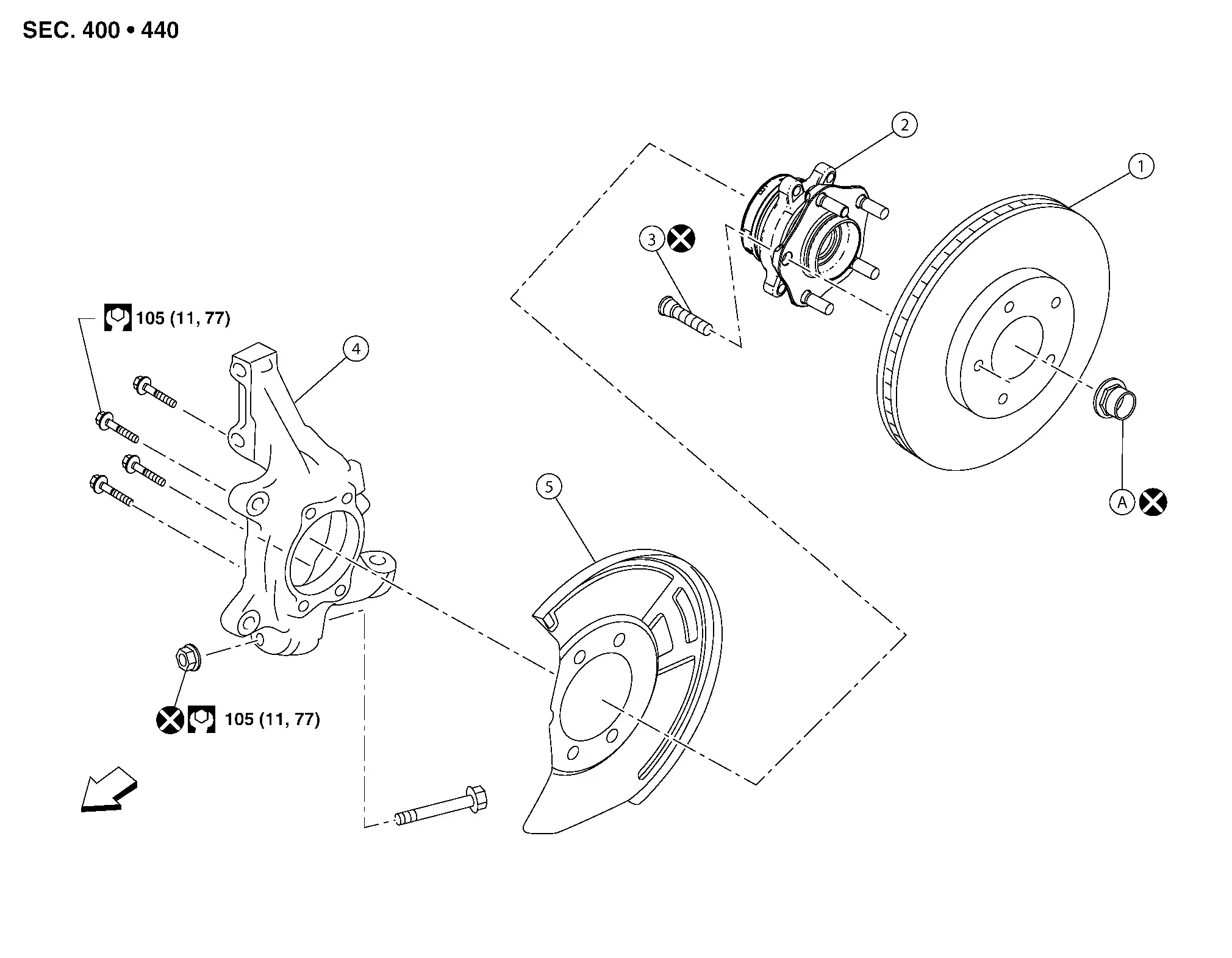
| 1. | Disc brake rotor | 2. | Wheel hub and bearing | 3. | Wheel stud |
| 4. | Steering knuckle | 5. | Splash guard |
 |
Front |
| A. | Refer to Installation. |
Removal and Installation
REMOVAL
Remove front disc brake rotor. Refer to Exploded View.
Remove wheel sensor bolt and position wheel sensor aside. Refer to Removal and Installation.
WARNING:
To avoid risk of death or severe personal injury:
-
Do not pull on wheel sensor harness.
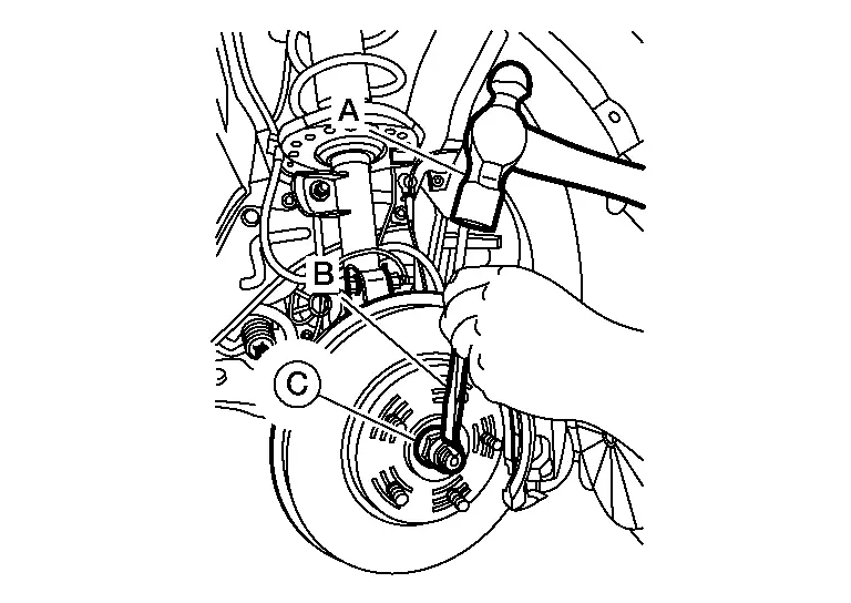
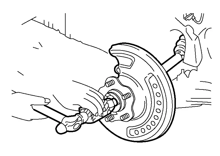
Using suitable tool (A) and Tool (B) release staked area (C) of wheel hub lock nut (D).

| Tool number (B) | : (NI-52982) |
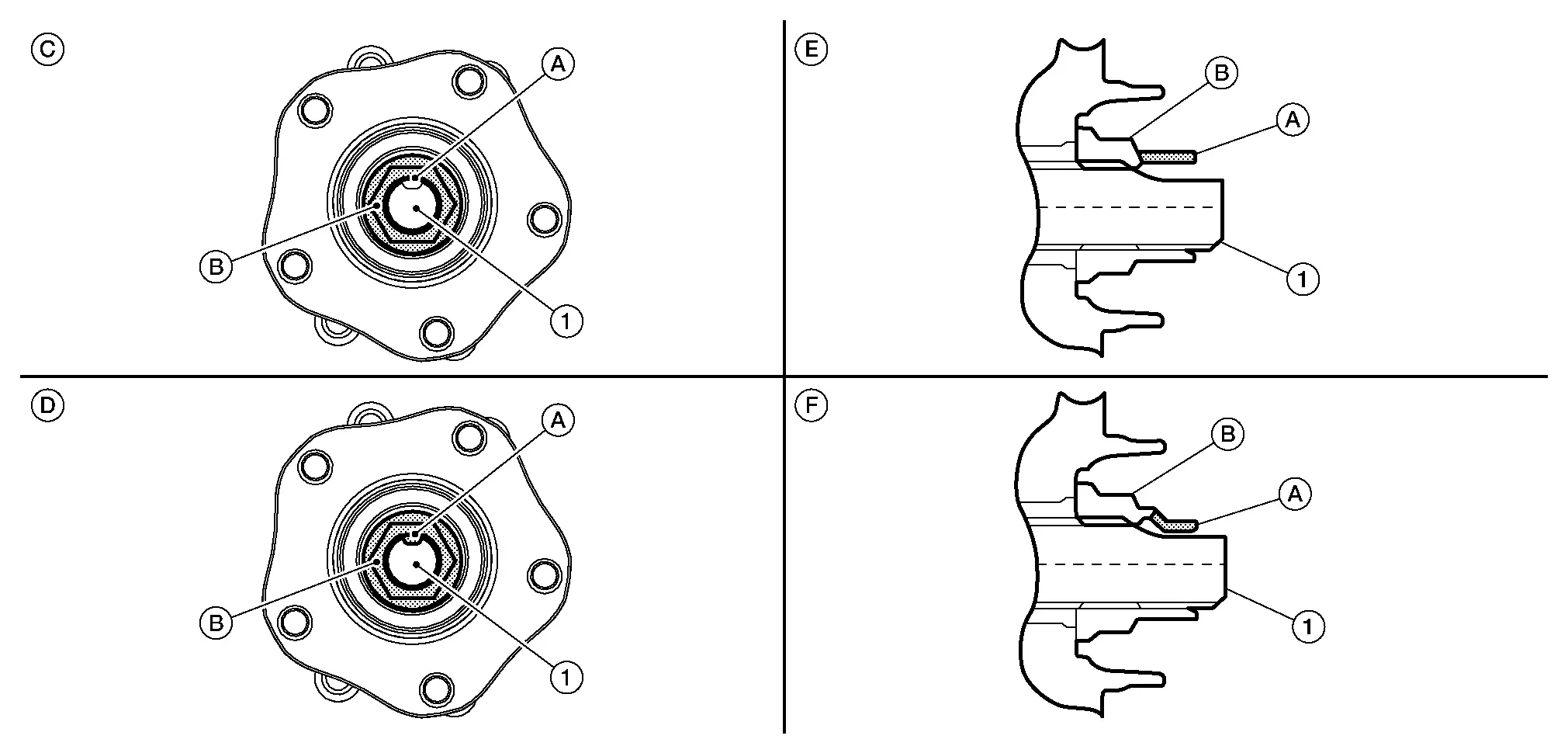
Visually verify that staked area (A) of wheel hub lock nut (B) is completely released from front drive shaft (1) or damage to drive shaft can occur.

| (C) | : Fully released |
| (D) | : Not fully released |
| (E) | : Fully released (sectional view) |
| (F) | : Not fully released (sectional view) |
WARNING:
To avoid risk of death or severe personal injury:
-
Be sure that staked area of wheel hub lock nut is fully released or damage to drive shaft can occur.
-
Do not damage front drive shaft threads.
Loosen lock nut from drive shaft.
WARNING:
To avoid risk of death or severe personal injury:
-
Do not use power tools.
-
Do not damage front drive shaft threads.
-
Do not reuse drive shaft lock nut.
-
When loosening lock nut, if it does not turn smoothly, verify that staked area is completely released.
Using a piece of wood and a suitable tool, tap on the lock nut to disengage drive shaft from wheel hub and bearing.

WARNING:
To avoid risk of death or severe personal injury:
-
Do not place drive shaft joint at an extreme angle. Be careful not to over extend slide joint.
-
Do not allow drive shaft to hang without support.
 NOTE:
NOTE:
Use suitable puller if drive shaft cannot be separated from wheel hub and bearing assembly.
Remove wheel hub lock nut.
WARNING:
To avoid risk of death or severe personal injury:
-
Do not reuse wheel hub lock nut.
Remove wheel hub and bearing bolts using power tool.
Remove splash guard and wheel hub and bearing assembly from steering knuckle.
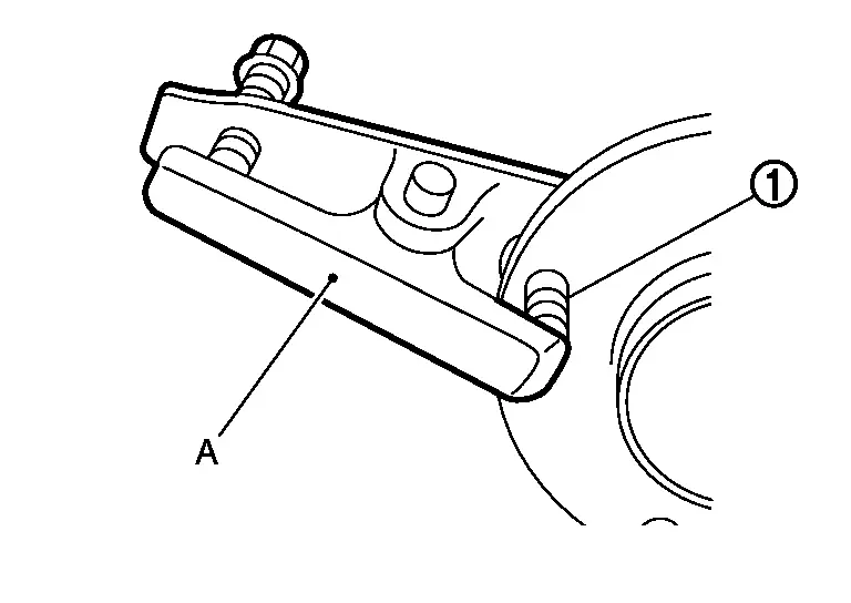
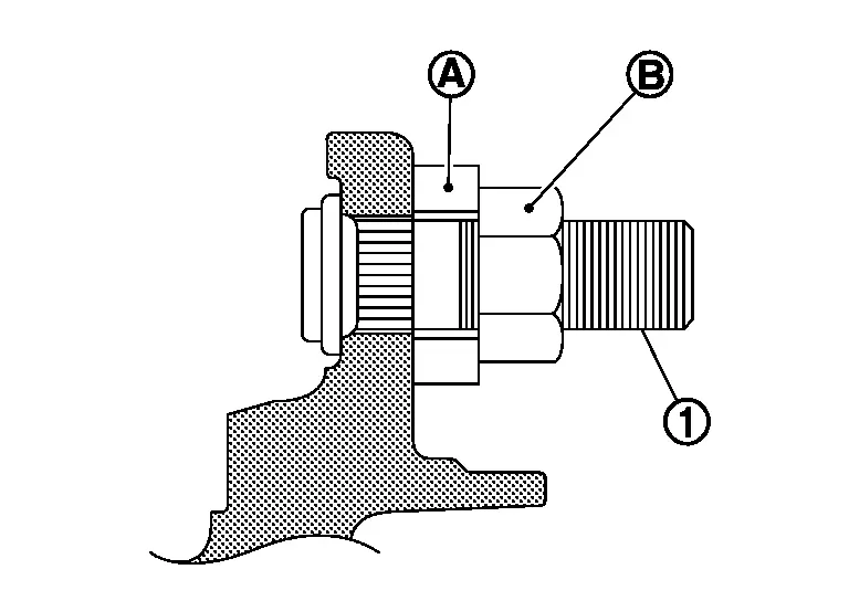
If necessary, remove wheel studs (1) using suitable tool (A).
INSPECTION AFTER REMOVAL
Check components for deformation, cracks, and other damage. Replace if necessary.
Ball joint inspection
Check for boot breakage, axial looseness, and torque of transverse link ball joint and repair as necessary.
INSTALLATION
Installation is in the reverse order of removal.
WARNING:
To avoid risk of death or severe personal injury:
-
Do not reuse wheel stud.
-
Do not reuse wheel hub lock nut.
-
Place a washer (A) as shown to install wheel studs (1) by using tightening force of nut (B).

WARNING:
To avoid risk of death or severe personal injury:
-
Do not apply lubricating oil to these mating surfaces.
-
Check that there is no clearance between wheel stud and wheel hub and bearing.
-
Do not use a power tool to tighten the wheel hub lock nut.
-
Align the marks made on the rotor and the front wheel hub during disassembly.
-
Do not reuse lower strut nut.
-
Do not reuse the wheel hub lock nut.
-
Clean mating surfaces of wheel hub lock nut and wheel hub and bearing.
-
Do not apply lubricating oil to these matching surface.
-
-
Clean the matching surface of drive shaft and wheel hub assembly. And then apply paste [service parts (440037S000)] to surface (A) of joint sub-assembly of drive shaft.

 NOTE:
NOTE:
To avoid damage to the Nissan Pathfinder vehicle:
-
Apply paste to cover entire flat surface of joint sub-assembly of drive shaft.
Paste amount : 1.0 – 3.0 g (0.04 – 0.10 oz)
-
-
Hold wheel hub and bearing using a suitable tool. Tighten wheel hub lock nut.
Wheel hub lock nut : 205 N·m (21 kg-m, 151 ft-lb) WARNING:
To avoid risk of death or severe personal injury:
-
Since drive shaft is assembled by press-fitting, use a torque wrench to tighten wheel hub lock nut. Do not use a power tool.
-
Too much torque causes axle noise. Too little torque causes wheel bearing looseness.
-
-
Using suitable tool (A) and cold chisel (B) stake the wheel hub lock nut (C) as shown.
WARNING:
To avoid the risk of death or severe personal injury:
-
Use the following range when staking the wheel hub lock nut.
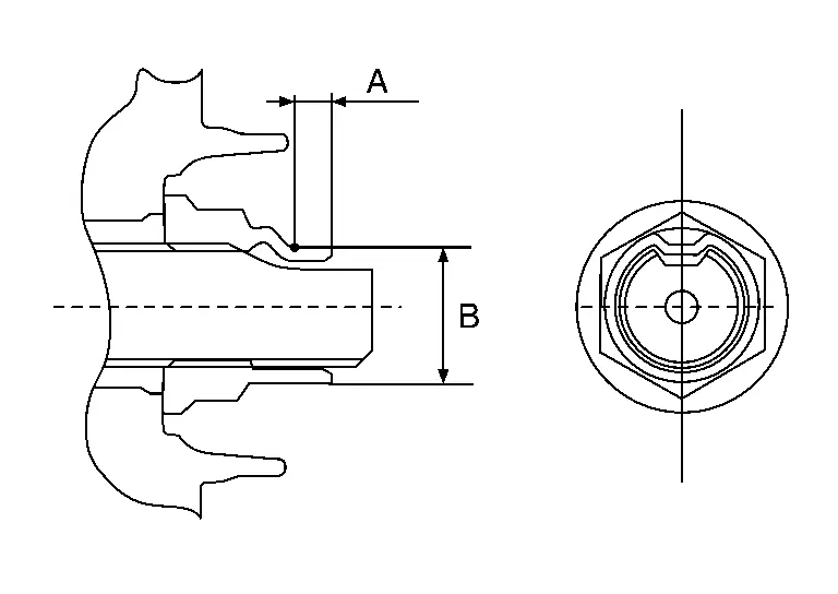
(A) : 6.2 mm (0.244 in) (B) : 26.4 - 27.8 mm (1.039 - 1.094 in) -
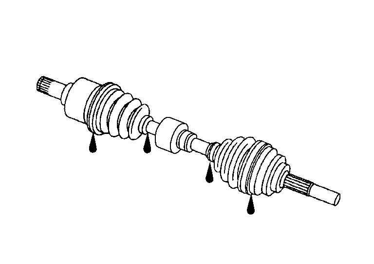
Front Drive Shaft Nissan Pathfinder SUV
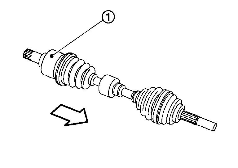
Exploded View
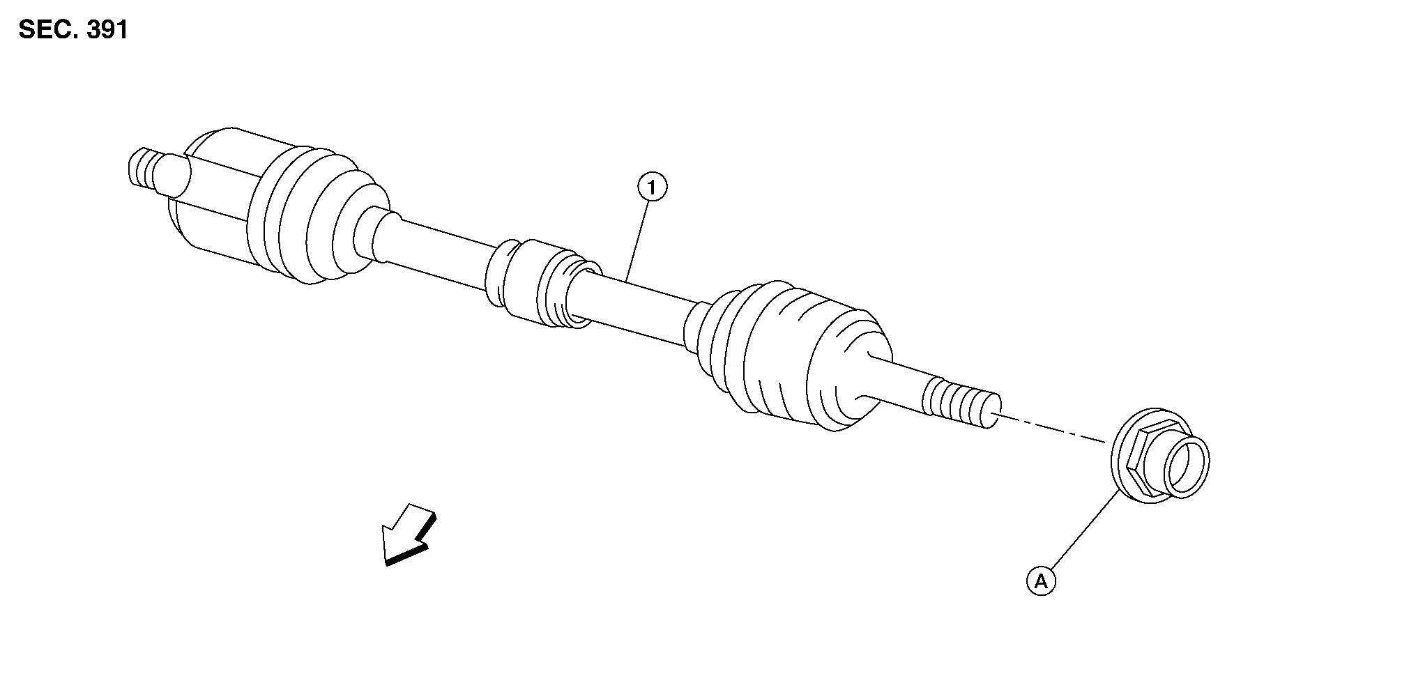
| 1. | Drive shaft | A. | Refer to Removal and Installation. |
 |
Front |
Removal and Installation (LH)
REMOVAL
Remove front disc brake rotor. Refer to Exploded View.
Remove wheel sensor bolt and position wheel sensor aside. Refer to Removal and Installation.
WARNING:
To avoid risk of death or severe personal injury:
-
Do not pull on wheel sensor harness.
Using suitable tool (A) and Tool (B) release staked area (C) of wheel hub lock nut (D).

| Tool number (B) | : (NI-52982) |
Visually verify that staked area (A) of wheel hub lock nut (B) is completely released from front drive shaft (1) or damage to drive shaft can occur.
| (C) | : Fully released |
| (D) | : Not fully released |
| (E) | : Fully released (sectional view) |
| (F) | : Not fully released (sectional view) |
WARNING:
To avoid risk of death or severe personal injury:
-
Be sure that staked area of wheel hub lock nut is fully released or damage to drive shaft can occur.
-
Do not damage front drive shaft threads.
Loosen wheel hub lock nut from drive shaft.
WARNING:
To avoid risk of death or severe personal injury:
-
Do not use power tool.
-
Do not damage front drive shaft threads.
-
Do not reuse drive shaft lock nut.
-
When loosening lock nut, if it does not turn smoothly, verify that staked area is completely released.
Using a piece of wood and a suitable tool, tap on the lock nut to disengage drive shaft from wheel hub.
WARNING:
To avoid risk of death or severe personal injury:
-
Do not place drive shaft joint at an extreme angle. Be careful not to over extend slide joint.
-
Do not allow drive shaft to hang without support.
 NOTE:
NOTE:
Use suitable puller if drive shaft cannot be separated from wheel hub and bearing assembly.
Remove wheel hub lock nut.
WARNING:
To avoid risk of death or severe personal injury:
-
Do not reuse wheel hub lock nut.
Remove the lower transverse link. Refer to Removal and Installation.
CAUTION:
Do not reuse pinch bolt nut.
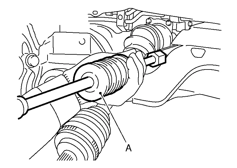
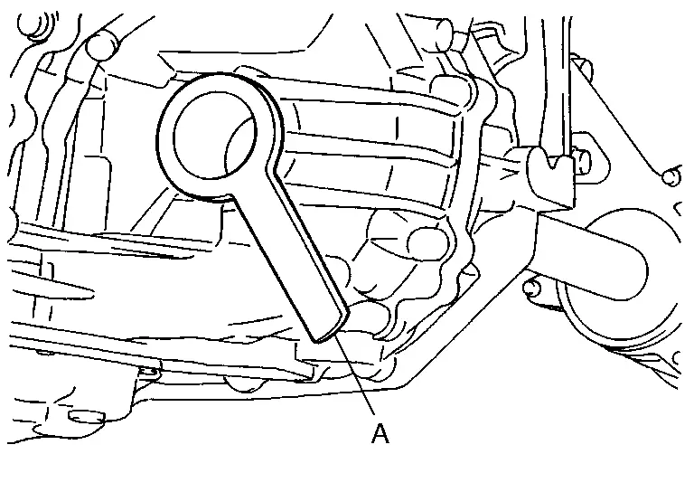
Insert suitable tool (A) between the drive shaft and the transaxle. Remove the drive shaft from the transaxle (LH/RH).

CAUTION:
-
Confirm that the circular clip is attached to the drive shaft.
-
Do not place the drive shaft joint at an extreme angle when removing the drive shaft. Also be careful not to overextend the slide joint.
| Tool (A) | : Drive shaft joint puller (Commercially available) |
Remove the differential side oil seal. Refer to Removal and Installation (LH) (LH) or Removal and Installation (RH) (RH).
CAUTION:
Do not reuse differential side oil seal.
INSPECTION AFTER REMOVAL
-
Move joint up/down, left/right, and in axial direction. Check for any rough movement or significant looseness.
-
Check boot for cracks or other damage, and for grease leakage.

-
If damaged, disassemble drive shaft to verify damage, and repair or replace as necessary.
INSTALLATION
Installation is in the reverse order of removal.
CAUTION:
-
Do not reuse the differential side oil seal.
-
Do not reuse the drive shaft circlip.
-
Do not reuse the wheel hub lock nut.
-
Do not use power tools to tighten the wheel hub lock nut.
-
Install a new differential side oil seal. Refer to Removal and Installation (LH) (LH) or Removal and Installation (RH) (RH).
-
In order to prevent damage to differential side oil seal, place Tool (A) onto oil seal before inserting drive shaft as shown. Slide drive shaft into slide joint and tap with a hammer to install securely.

Tool number (A) : KV38107900 (NI-52469-1) -
Install new circlip on drive shaft in the circular clip groove on transaxle side. Refer to Disassembly and Assembly (LH).
WARNING:
Ensure that circular clip is properly engaged, otherwise the joint subassembly could pull away from transaxle during Nissan Pathfinder vehicle operation resulting in loss of drive force and possible drive shaft damage, which may cause a crash and serious injury or damage the drive shaft.
-
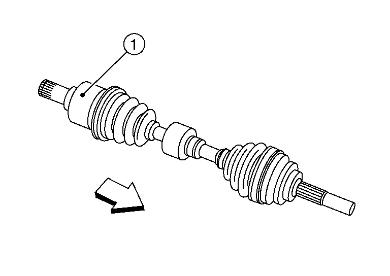
To ensure the circular clip is properly engaged, grasp the housing (1) and pull back and forth in axial direction while listening for clicking sounds.
-
Pull the joint sub-assembly in the axial direction away from transaxle assembly (
 ). Confirm that the joint sub assembly cannot be pulled out.
WARNING:
To avoid risk of death or severe personal injury:
-
Do not reuse wheel stud.
-
Do not reuse wheel hub lock nut.
-
Place a washer (A) as shown to install wheel studs (1) by using tightening force of nut (B).
WARNING:
To avoid risk of death or severe personal injury:
-
Do not apply lubricating oil to these mating surfaces.
-
Check that there is no clearance between wheel stud and wheel hub and bearing.
-
Do not use a power tool to tighten the wheel hub lock nut.
-
Align the marks made on the rotor and the front wheel hub during disassembly.
-
Do not reuse lower strut nut.
-
Do not reuse the wheel hub lock nut.
-
Clean mating surfaces of wheel hub lock nut and wheel hub and bearing.
-
Do not apply lubricating oil to these matching surface.
-
-
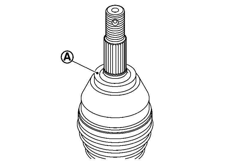
Clean the matching surface of drive shaft and wheel hub assembly. And then apply paste [service parts (440037S000)] to surface (A) of joint sub-assembly of drive shaft.

 NOTE:
NOTE:
To avoid damage to the Nissan Pathfinder vehicle:
-
Apply paste to cover entire flat surface of joint sub-assembly of drive shaft.
Paste amount : 1.0 – 3.0 g (0.04 – 0.10 oz)
-
-
-
Hold wheel hub and bearing using a suitable tool. Tighten wheel hub lock nut.
Wheel hub lock nut : 205 N·m (21 kg-m, 151 ft-lb) WARNING:
To avoid risk of death or severe personal injury:
-
Since drive shaft is assembled by press-fitting, use a torque wrench to tighten wheel hub lock nut. Do not use a power tool.
-
Too much torque causes axle noise. Too little torque causes wheel bearing looseness.
-
Do not reuse the wheel hub lock nut.
-
-
Using suitable tool (A) and cold chisel (B) stake the wheel hub lock nut (C) as shown.

WARNING:
To avoid the risk of death or severe personal injury:
-
Use the following range when staking the wheel hub lock nut.

(A) : 6.2 mm (0.244 in) (B) : 26.4 - 27.8 mm (1.039 - 1.094 in) -
-
Align the marks on the disc brake rotor and on the wheel hub and bearing.
-
Tighten wheel nuts to specification. Refer to Adjustment.
INSPECTION AND ADJUSTMENT AFTER INSTALLATION
-
Check A/T fluid level and leakage. Refer to Inspection.
-
Check wheel alignment. Refer to Inspection.
-
Adjust the neutral position of the steering angle sensor. Refer to Description.
Exploded View
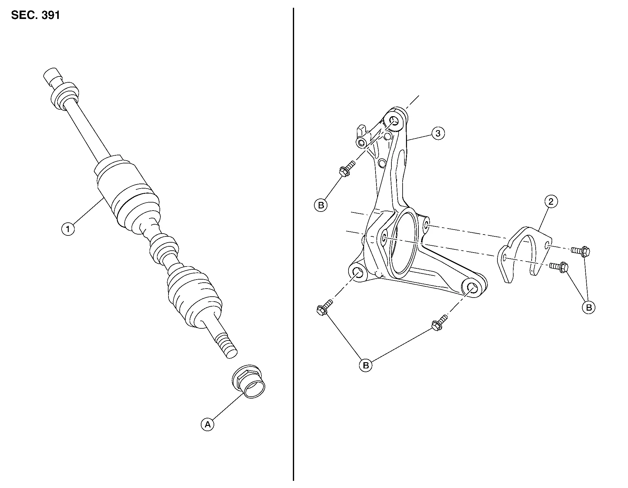
| 1. | Drive shaft | 2. | Bearing retainer | 3. | Support bearing bracket |
| A. | Refer to Removal and Installation. | B. | Refer to Removal and Installation. |
Removal and Installation (RH)
REMOVAL
Remove front disc brake rotor. Refer to Removal and Installation.
Remove wheel sensor bolt and position wheel sensor aside. Refer to Removal and Installation.
WARNING:
To avoid risk of death or severe personal injury:
-
Do not pull on wheel sensor harness.
Using suitable tool (A) and Tool (B) release staked area (C) of wheel hub lock nut (D).
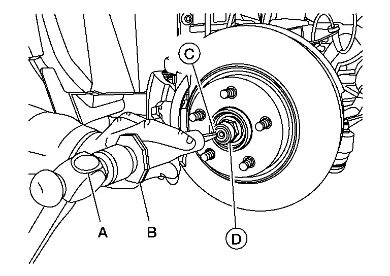
| Tool number (B) | : (NI-52982) |
Visually verify that staked area (A) of wheel hub lock nut (B) is completely released from front drive shaft (1) or damage to drive shaft can occur.

| (C) | : Fully released |
| (D) | : Not fully released |
| (E) | : Fully released (sectional view) |
| (F) | : Not fully released (sectional view) |
WARNING:
To avoid risk of death or severe personal injury:
-
Be sure that staked area of wheel hub lock nut is fully released or damage to drive shaft can occur.
-
Do not damage front drive shaft threads.
Loosen wheel hub lock nut from drive shaft.
WARNING:
To avoid risk of death or severe personal injury:
-
Do not use power tool.
-
Do not damage front drive shaft threads.
-
Do not reuse drive shaft lock nut.
-
When loosening lock nut, if it does not turn smoothly, verify that staked area is completely released.
Disconnect stabilizer bar end link from stabilizer bar. Refer to Exploded View
Using a piece of wood and a suitable tool, tap on the lock nut to disengage drive shaft from wheel hub.

WARNING:
To avoid risk of death or severe personal injury:
-
Do not place drive shaft joint at an extreme angle. Be careful not to over extend slide joint.
-
Do not allow drive shaft to hang without support.
 NOTE:
NOTE:
Use suitable puller if drive shaft cannot be separated from wheel hub and bearing assembly.
Remove wheel hub lock nut.
WARNING:
To avoid risk of death or severe personal injury:
-
Do not reuse wheel hub lock nut.
Remove steering the knuckle. Refer to Removal and Installation.
Remove bearing retainer to support bearing bracket bolts.
Insert suitable tool (A) between the drive shaft and the transaxle. Remove the drive shaft from the transaxle.
CAUTION:
-
Confirm that the circular clip is attached to the drive shaft.
-
Do not place the drive shaft joint at an extreme angle when removing the drive shaft. Also be careful not to overextend the slide joint.
| Tool (A) | : Drive shaft joint puller (Commercially available) |
If necessary, remove support breaking bracket bolts and support bearing bracket.
Remove differential side oil seal. Refer to Removal and Installation (LH) (LH) or Removal and Installation (RH) (RH).
INSPECTION AFTER REMOVAL
-
Move joint up/down, left/right, and in axial direction. Check for any rough movement or significant looseness.
-
Check boot for cracks or other damage, and for grease leakage.
-
If damaged, disassemble drive shaft to verify damage, and repair or replace as necessary.
INSTALLATION
Install a new differential side oil seal. Refer to Removal and Installation (LH) (LH) or Removal and Installation (RH) (RH).
CAUTION:
Do not reuse the differential side oil seal.
 NOTE:
NOTE:
4WD model has dust shield that is reusable and stays in transfercase.
-
In order to prevent damage to differential side oil seal, place Tool (A) onto oil seal before inserting drive shaft as shown. Slide drive shaft into slide joint and tap with a hammer to install securely.
Tool number : KV38107900 (NI-52469-1)
Tighten the bearing retainer bolts in the numerical order shown.
-
Refer to the following for installation.
M8 bolt : No. 1 and No. 2 21.1 N·m (2.2 kg-m, 16 ft-lb) 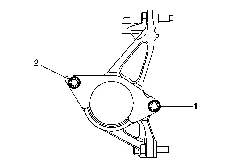
Tighten support bearing bracket bolts in the numerical order as shown.
-
Refer to the following for installation.
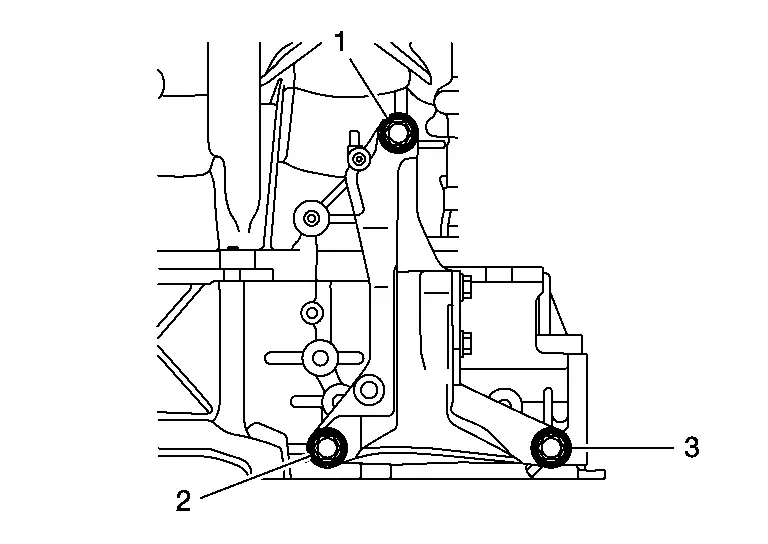
-
Finger tighten bolts No. 1, No. 2 and No. 3.
-
Tighten bolts No. 1, No. 2 and No. 3 to specified torque.
M10 bolt : No. 1 - 3 48.0 N·m (4.9 kg-m, 35 ft-lb) -
Install new circular clip on drive shaft in circular clip groove on transaxle side. Refer to Disassembly and Assembly (RH).
CAUTION:
-
Do not reuse circular clip.
-
Make sure new circular clip on drive shaft is securely fastened.
WARNING:
Ensure that the circular clip is properly engaged, otherwise the joint sub-assembly could pull away from transaxle during Nissan Pathfinder vehicle operation resulting in loss of drive force and possible drive shaft damage, which may cause a crash and serious injury or damage the drive shaft.
-
To ensure the circular clip is properly engaged, grasp the housing (1) and pull back and forth in axial direction while listening for clicking sounds.
-
Pull the joint sub-assembly in the axial direction away from the transaxle assembly (
 ). Confirm that the joint sub assembly cannot be pulled out.
WARNING:
To avoid risk of death or severe personal injury:
-
Do not reuse wheel stud.
-
Do not reuse wheel hub lock nut.
-
Place a washer (A) as shown to install wheel studs (1) by using tightening force of nut (B).

WARNING:
To avoid risk of death or severe personal injury:
-
Do not apply lubricating oil to these mating surfaces.
-
Check that there is no clearance between wheel stud and wheel hub and bearing.
-
Do not use a power tool to tighten the wheel hub lock nut.
-
Align the marks made on the rotor and the front wheel hub during disassembly.
-
Do not reuse lower strut nut.
-
Do not reuse the wheel hub lock nut.
-
Clean mating surfaces of wheel hub lock nut and wheel hub and bearing.
-
Do not apply lubricating oil to these matching surface.
-
-
Clean the matching surface of drive shaft and wheel hub assembly. And then apply paste [service parts (440037S000)] to surface (A) of joint sub-assembly of drive shaft.
 NOTE:
NOTE:
To avoid damage to the Nissan Pathfinder vehicle:
Apply paste to cover entire flat surface of joint sub-assembly of drive shaft.
Paste amount : 1.0 – 3.0 g (0.04 – 0.10 oz)
-
Hold wheel hub and bearing using a suitable tool. Tighten wheel hub lock nut.
Wheel hub lock nut : 205 N·m (21 kg-m, 151 ft-lb) WARNING:
To avoid risk of death or severe personal injury:
-
Since drive shaft is assembled by press-fitting, use a torque wrench to tighten wheel hub lock nut. Do not use a power tool.
-
Too much torque causes axle noise. Too little torque causes wheel bearing looseness.
-
-
Using suitable tool (A) and cold chisel (B) stake the wheel hub lock nut (C) as shown.

WARNING:
To avoid the risk of death or severe personal injury:
-
Use the following range when staking the wheel hub lock nut.

(A) : 6.2 mm (0.244 in) (B) : 26.4 - 27.8 mm (1.039 - 1.094 in) -
Remainder of installation is in the reverse order of removal.
INSPECTION AND ADJUSTMENT AFTER INSTALLATION
-
Check A/T fluid level and leakage. Refer to Inspection.
-
Check wheel alignment. Refer to Inspection.
-
Adjust the neutral position of the steering angle sensor. Refer to Description.

Nissan Pathfinder (R53) 2022-2026 Service Manual
Removal and Installation
Contact Us
Nissan Pathfinder Info Center
Email: info@nipathfinder.com
Phone: +1 (800) 123-4567
Address: 123 Pathfinder Blvd, Nashville, TN 37214, USA
Working Hours: Mon–Fri, 9:00 AM – 5:00 PM (EST)
