Nissan Pathfinder: Fuel System - Removal and Installation
- Fuel Level Sensor Unit, Fuel Filter and Fuel Pump Assembly
- Fuel Tank
- Evap Canister
- Evap Canister Filter
- Evap Canister Vent Control Valve
- Evap Control System Pressure Sensor
- Evap Canister Volume Control Solenoid Valve
Fuel Level Sensor Unit, Fuel Filter and Fuel Pump Assembly Nissan Pathfinder 5th Gen
Exploded View
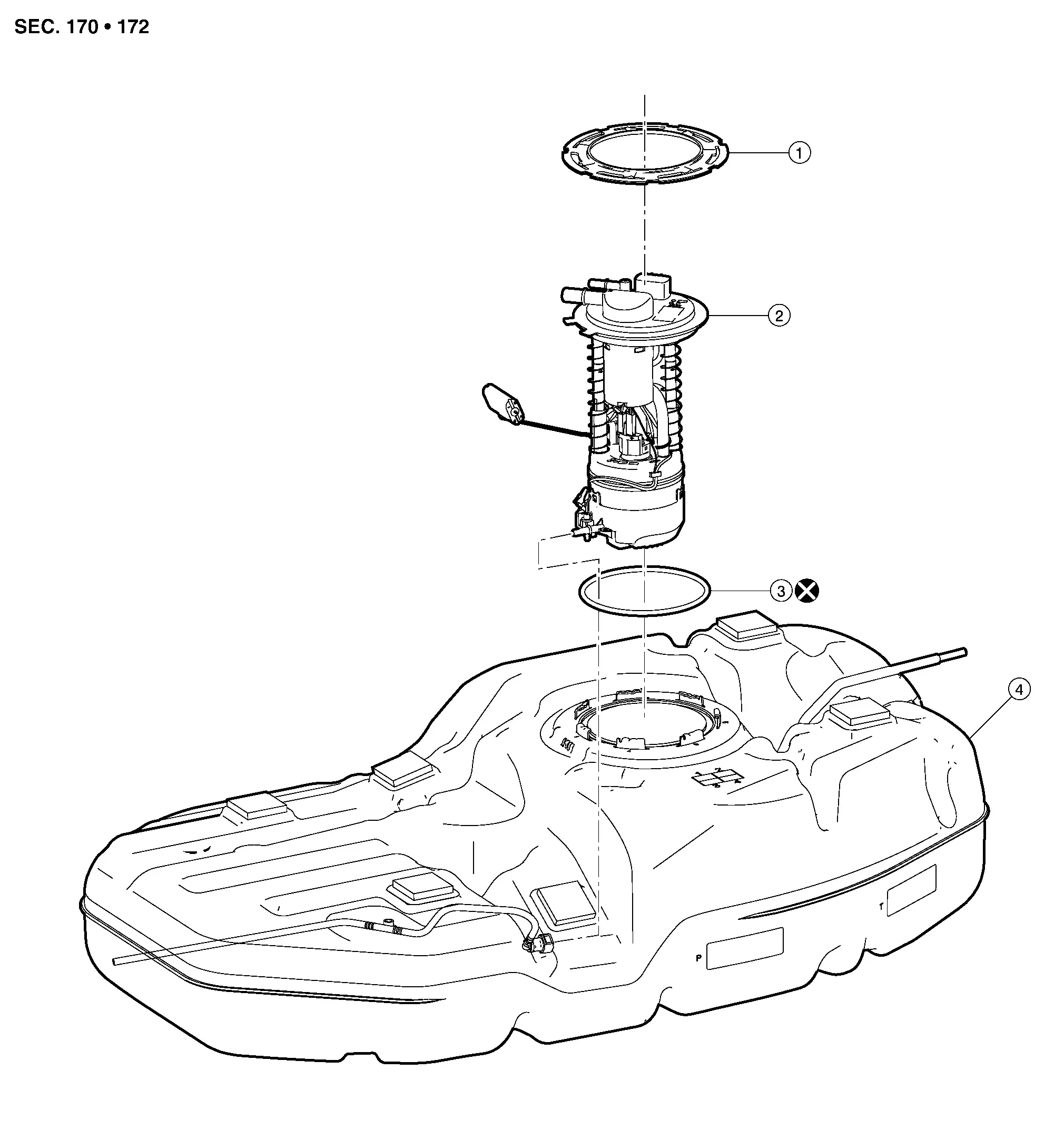
| 1. | Lock ring | 2. | Fuel level sensor unit, fuel filter and fuel pump assembly | 3. | O-ring |
| 4. | Fuel tank |
Removal and Installation
WARNING:
Read “General Precautions” before working on the fuel system. Refer to General Precautions.
CAUTION:
Do not remove or disassemble parts unless instructed as shown.
 NOTE:
NOTE:
When removing components such as hoses, tubes/lines, etc., cap or plug openings to prevent fluid from spilling.
REMOVAL
Using suitable tool open filler neck valve to release the pressure inside the fuel tank.
Release the fuel pressure from the fuel lines. Refer to Work Procedure.
Remove second row seat (LH). Refer to Removal and Installation.
Position and secure the carpet to gain access to the fuel pump inspection hole cover.
CAUTION:
Cover the immediate area surrounding the fuel pump inspection hole cover with plastic to avoid gasoline damage to the carpet.
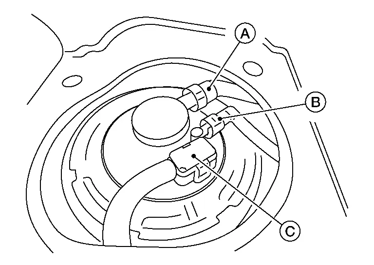
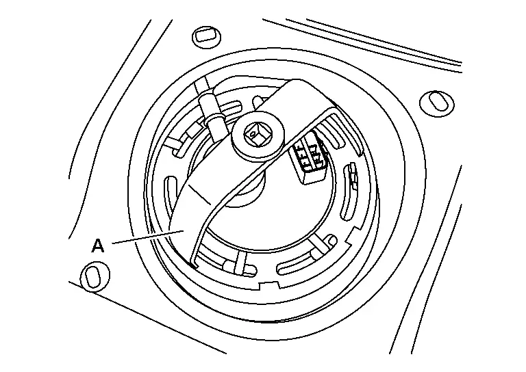
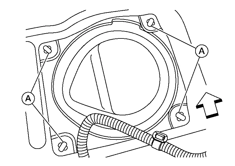
Turn the four retainers (A) 90 degrees to disengage the clips and remove the fuel pump inspection hole cover.

 |
: Front |
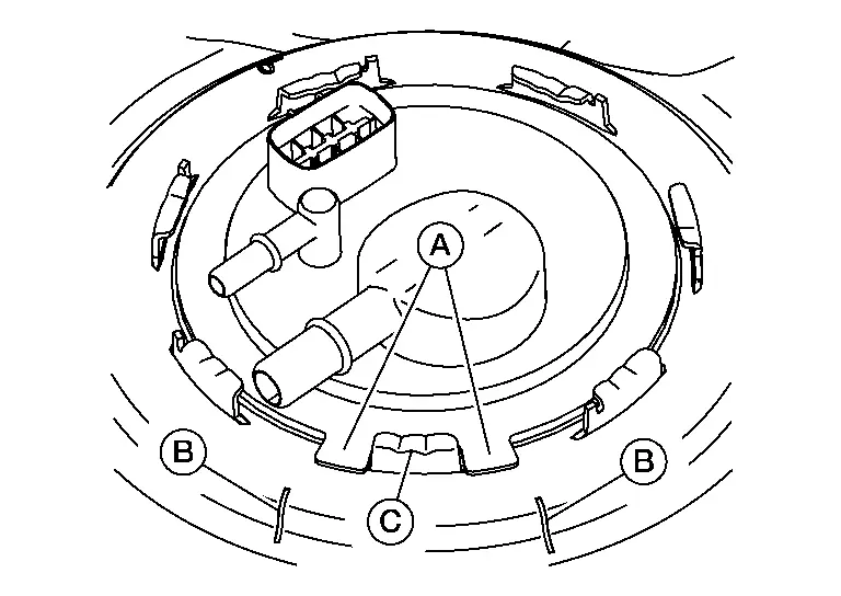
Disconnect the fuel level sensor unit, fuel filter, and fuel pump assembly harness connector (C), EVAP hose connector (A), and the fuel feed hose connector (B) from the fuel level sensor unit, fuel filter, and fuel pump assembly.
-
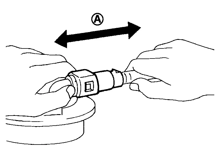
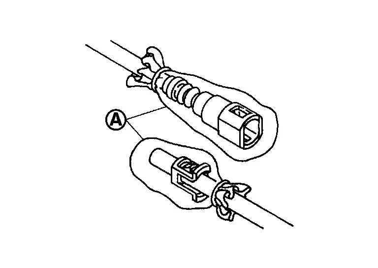
Disconnect the quick connector as follows:
-
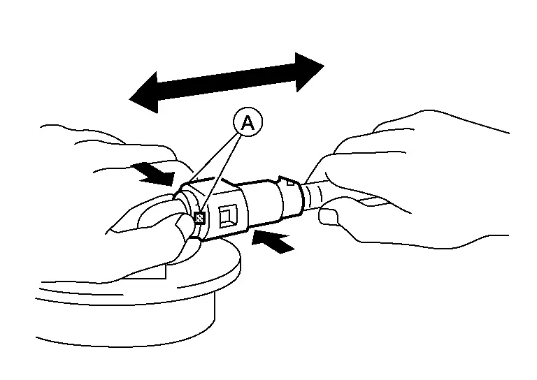
Hold the sides of the connector, push in tabs (A) and pull out the tube.
-
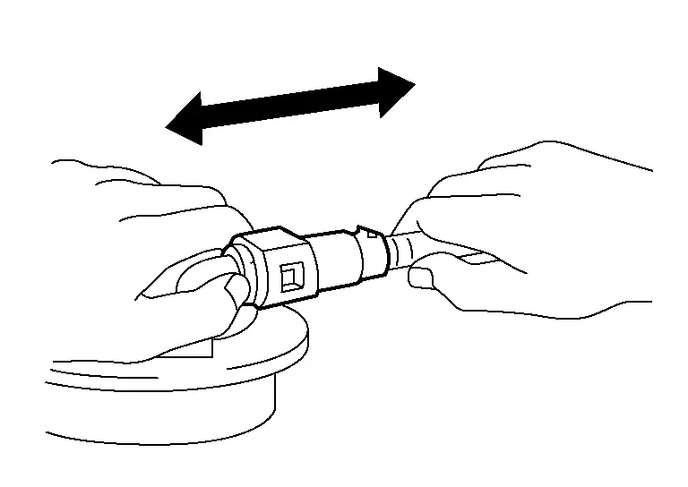
If the connector and the tube are stuck together, push and pull several times until they start to move. Then disconnect them by pulling.
-
CAUTION:
-
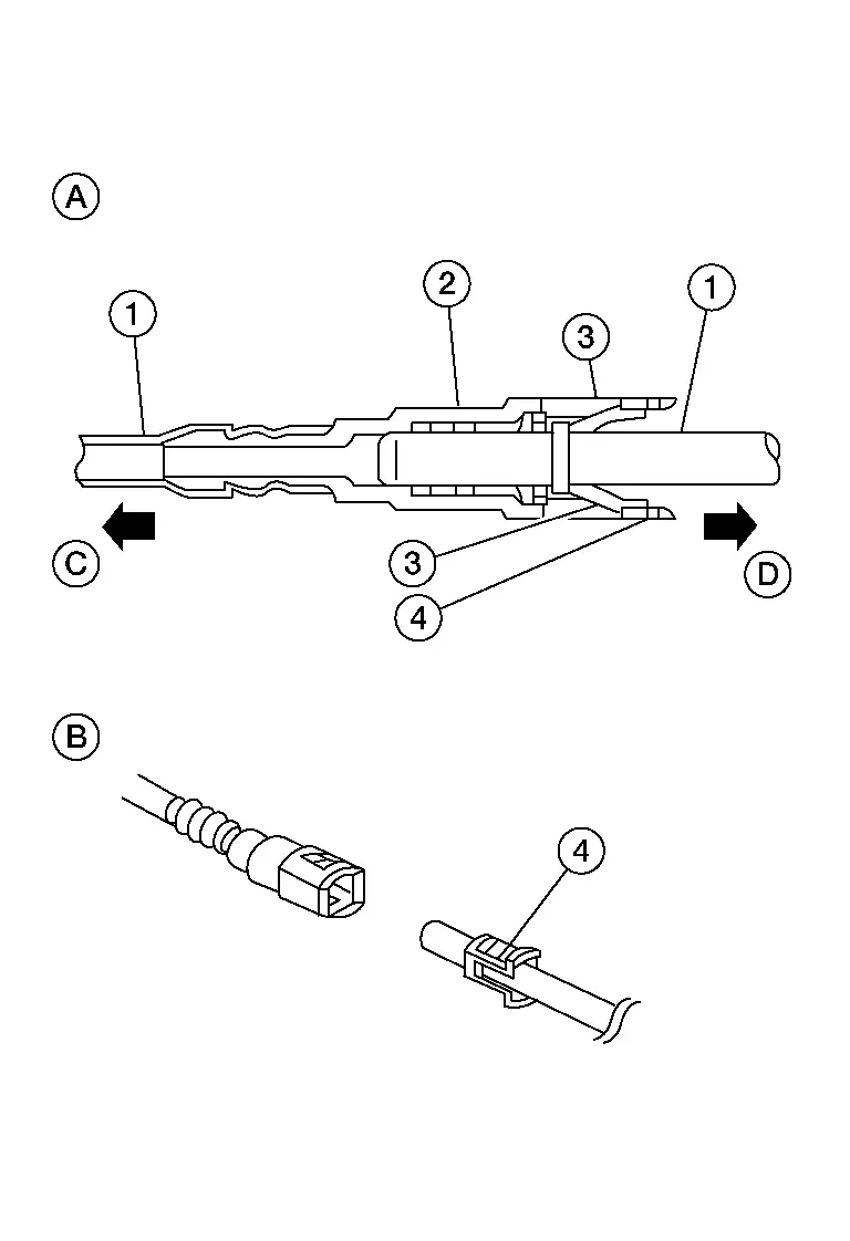
Quick connector (1) can be disconnected when the tabs (F) are depressed completely. Do not twist it more than necessary.
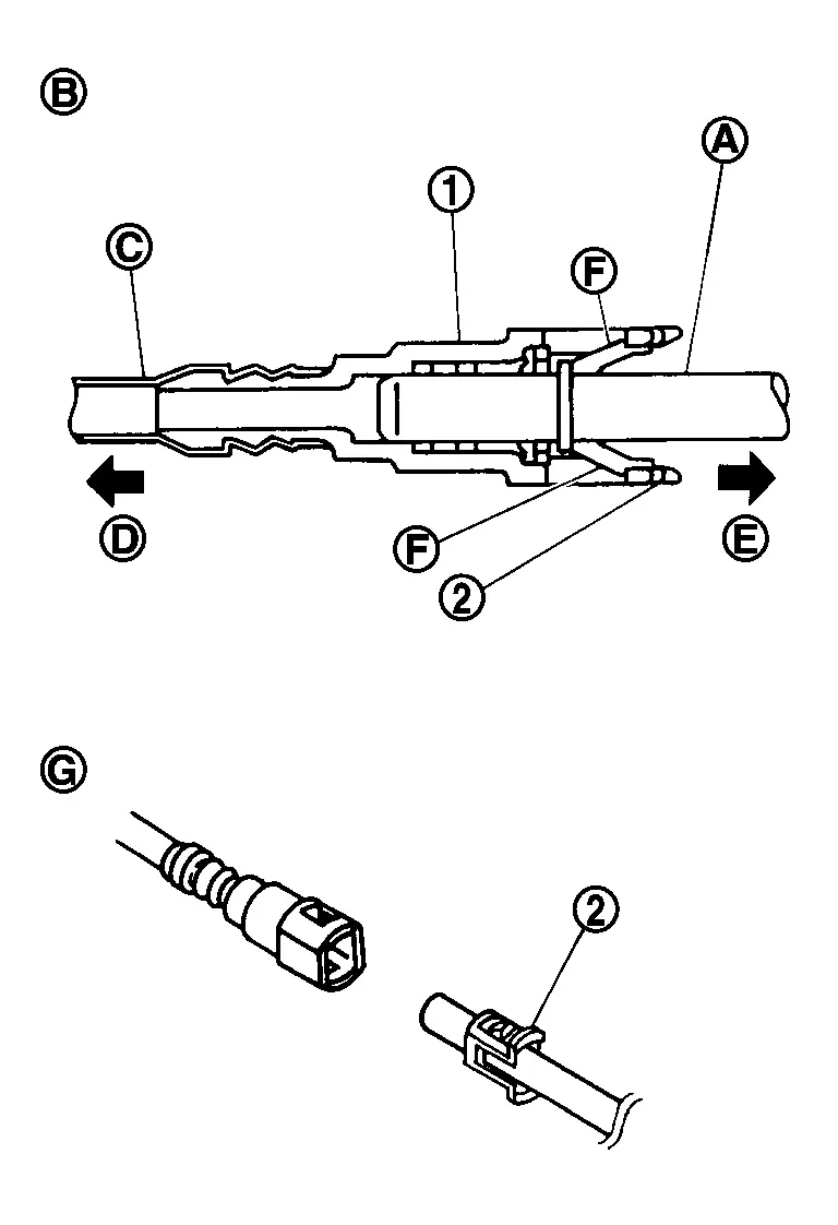
(B) : Connection (cross-section) (D) : To under floor fuel line (E) : To fuel tank (G) : Disconnection -
Do not use any tools to disconnect quick connector.
-
Keep resin tube (C) away from heat. Be especially careful when welding near the resin tube.
-
Prevent acid liquid such as battery electrolyte, etc. from getting on resin tube.
-
Do not bend or twist resin tube during installation and disconnection.
-
Do not remove the remaining retainer (2) on hard tube (or the equivalent) (A) except when resin tube or retainer is replaced.
-
When resin tube or hard tube (or the equivalent) is replaced, also replace retainer with new one.
-
To keep the connecting portion clean and to avoid damage and foreign materials, cover them completely with plastic bags (A) or something similar.

Remove the lock ring from the fuel level sensor unit, fuel filter, and fuel pump assembly.
-
Remove the lock ring using Tool (A).
Tool number (A) : — (NI-45722) (shown)
: KV101207S0 ( — )
: Front -
Prior to removal, observe the alignment between the fuel level sensor unit, fuel filter, and fuel pump assembly tabs (A) and the matching marks (B) on the fuel tank as shown. This alignment is necessary for proper installation.

(C) : Retainer pawl
Raise the fuel level sensor unit, fuel filter, and fuel pump assembly high enough to gain access and disconnect the transfer tube connector (A).
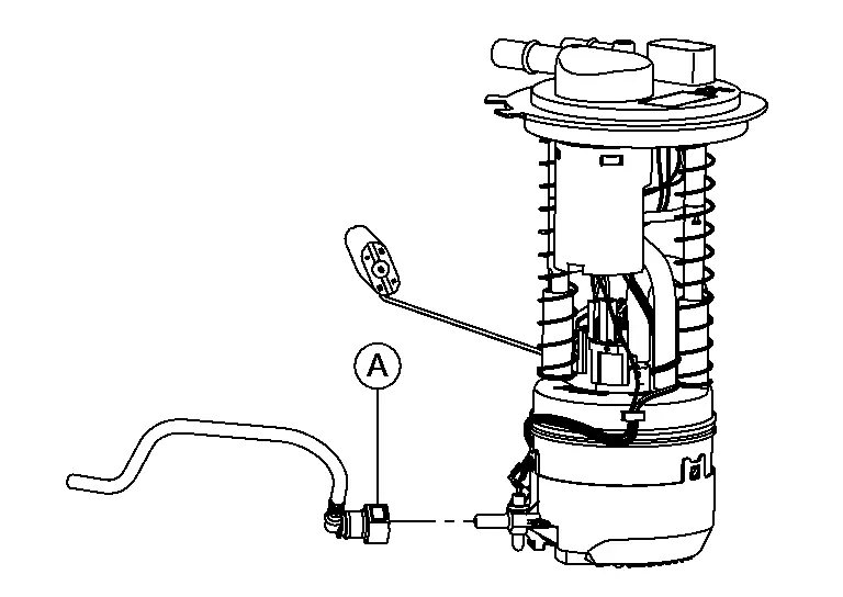
CAUTION:
Do not pull on the transfer tube or damage to the fuel tank can occur.
Remove the fuel level sensor unit, fuel filter, and fuel pump assembly and O-ring. Discard the O-ring.
CAUTION:
-
Do not bend the float arm during removal.
-
Do not reuse O-ring.
INSPECTION AFTER REMOVAL
Inspect the fuel level sensor unit, fuel filter, and fuel pump for any defects and foreign materials. Replace as necessary.
INSTALLATION
Install the fuel level sensor, fuel filter, and fuel pump assembly with the following procedure:
CAUTION:
-
It is important that the fuel level sensor unit, fuel filter, and fuel pump assembly be installed carefully, according to the method in this step to prevent the transfer hose from being pinched under the fuel pump and to ensure it is routed correctly inside the tank.
-
Do not reuse O-ring.
-
Do not bend the float arm during installation.
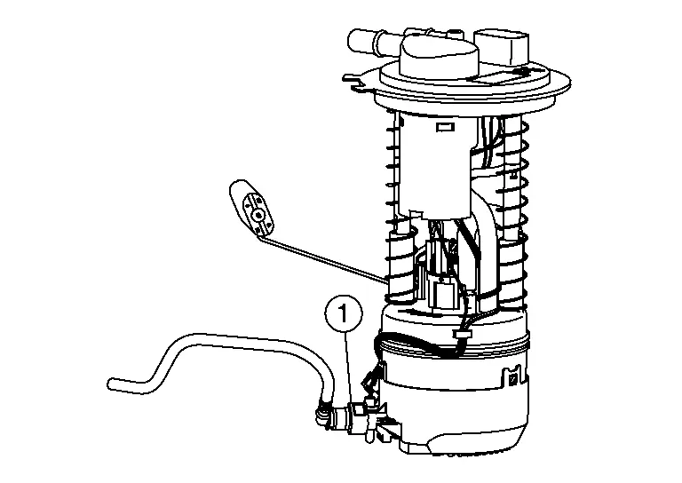
 NOTE:
NOTE:
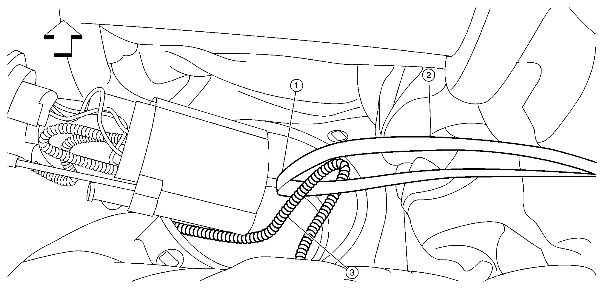
Transfer hose (1) should be routed as shown.
-
Packing strap is commonly used to reinforce boxes for shipping.
-
Position the strap ends toward the passenger side.
-
Use your fingers to put a bend (1) in the strap near the transfer hose (3). This will help keep the strap in place.
 |
: Front |
-
The fuel level sensor unit, fuel filter and fuel pump assembly should now be oriented to the installed position.
 NOTE:
NOTE:
If you are unable to pull the transfer hose so it can be seen as shown, remove the fuel level sensor unit, fuel filter and fuel pump assembly from the tank and restart from the beginning of INSTALLATION.
Hold the fuel pump down so the bottom of the pump stays against the bottom of the tank. While holding the pump down, pull out the packing strap, pull towards the passenger side.-
Make sure the O-ring is still in place.
 NOTE:
NOTE:
-
If the fuel level sensor unit, fuel filter and fuel pump assembly is allowed to lift off of the bottom of the fuel tank the transfer hose may slide under it.
-
If the fuel level sensor unit, fuel filter and fuel pump assembly lifts off the bottom of the tank before the lock ring is installed, remove the fuel level sensor unit, fuel filter and fuel pump assembly and restart from the beginning of INSTALLATION.
| Tool number (A) |
: — (NI-45722) (shown) : KV101207S0 ( — ) |

 |
: Front |

| (C) | : Retainer pawl |
Reconnect the EVAP hose (A), fuel feed hose (B) and harness connector (C).

-
Check the connection for damage or any foreign materials.
-
Align the connector with the tube, then insert the connector straight into the tube until a “click” sound is heard.
-
After connecting, check that the connection is secured with following procedures.
-
Visually confirm that the two tabs are connected to the connector.
-
Pull (A) the tube and the connector to check that they are securely connected.
-
-
After the tube is connected, make sure the connection is secure by performing the following checks:
-
Pull the tube and the connector to make sure they are securely connected.
-
Visually confirm that the two retainer tabs (3) are connected to the quick connector (2).

(1) Resin tube
(4) Retainer
(A): Connector (cross section)
(B): Disconnection
(C): To under floor fuel line
(D): To fuel tank
-
Installation of the remaining components is in the reverse order of removal.
INSPECTION AFTER INSTALLATION
Use the following procedure to check for fuel leaks.
With the ignition in the ON position (without starting the engine) to apply fuel pressure to the fuel system, then check the connections for fuel leaks.
Start engine, raise idle, and verify there are no fuel leaks at the fuel system connections.
Fuel Tank Nissan Pathfinder
Exploded View
For USA and Canada
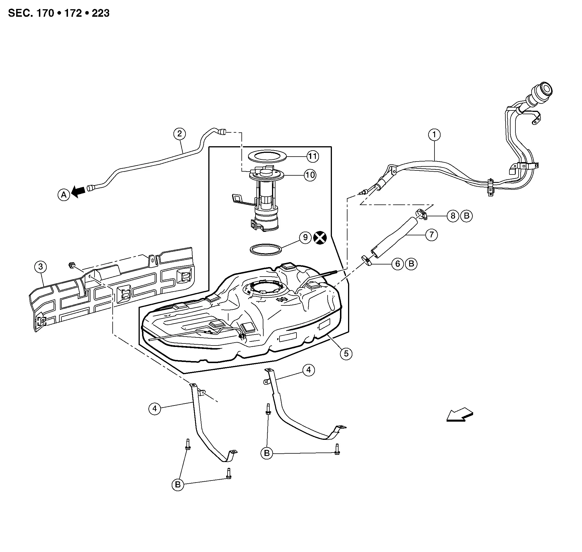
| 1. | Fuel filler tube | 2. | EVAP vent tube | 3. | Fuel tank protector |
| 4. | Fuel tank mounting straps | 5. | Fuel tank assembly | 6. | Clamp |
| 7. | Fuel filler hose | 8. | Clamp | 9. | O-ring |
| 10. | Fuel level sensor unit, fuel filter and fuel pump assembly | 11. | Lock ring | A. | To EVAP canister. Refer to Exploded View. |
| B. | Refer to Removal and Installation. |
 |
Front |
For Mexico
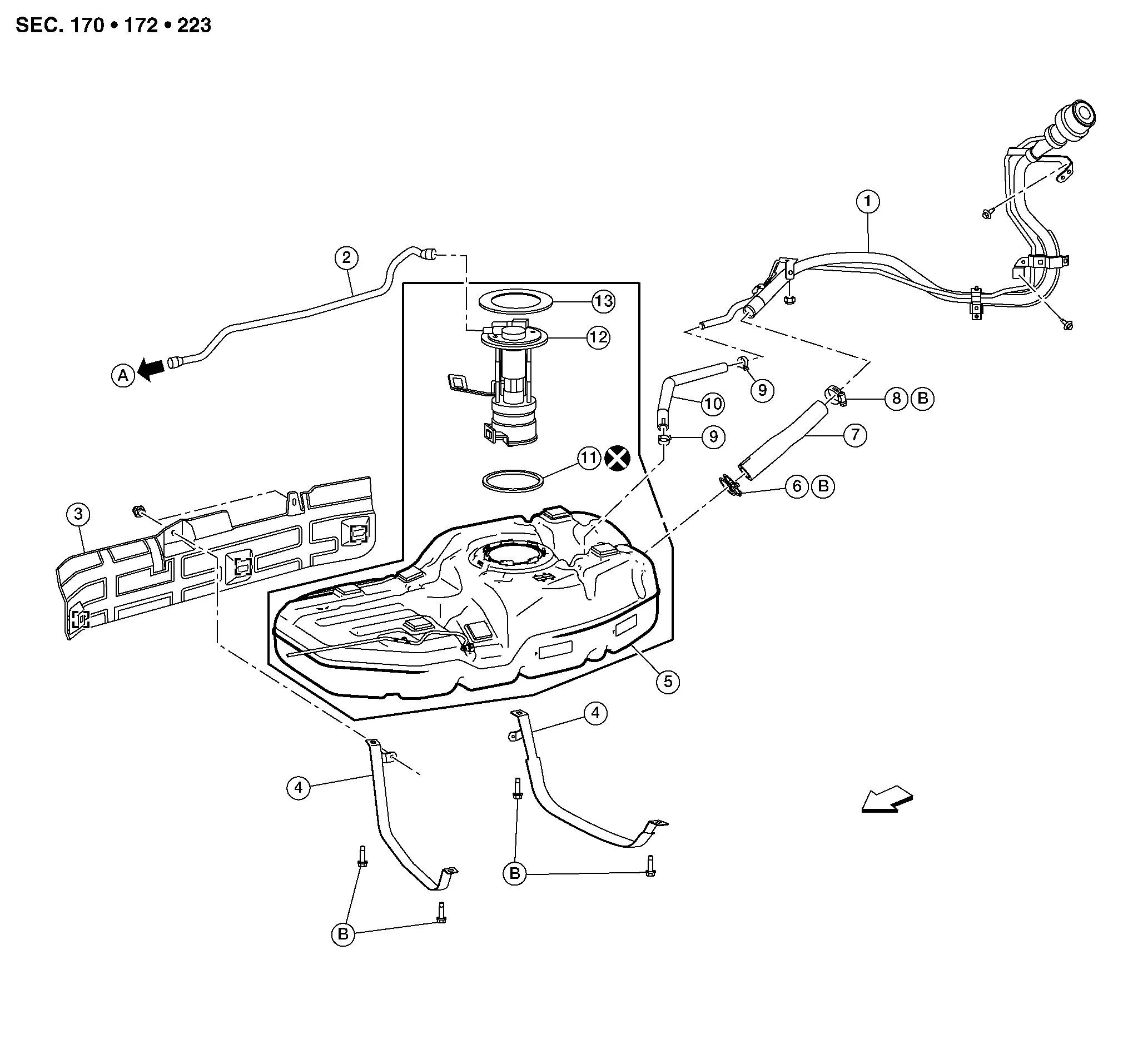
| 1. | Fuel filler tube | 2. | EVAP vent tube | 3. | Fuel tank protector |
| 4. | Fuel tank mounting straps | 5. | Fuel tank assembly | 6. | Clamp |
| 7. | Fuel filler hose | 8. | Clamp | 9. | Clamp |
| 10. | Vent hose | 11. | O-ring | 12. | Fuel level sensor unit, fuel filter and fuel pump assembly |
| 13. | Lock ring | A. | To EVAP canister. Refer to Exploded View. | B. | Refer to Removal and Installation. |
 |
Front |
Removal and Installation
WARNING:
Read “General Precautions” before working on the fuel system. Refer to General Precautions.
 NOTE:
NOTE:
When removing components such as hoses, tubes/lines, etc., cap or plug openings to prevent fluid from spilling.
REMOVAL
Using suitable tool open filler neck valve to release the pressure inside the fuel tank.
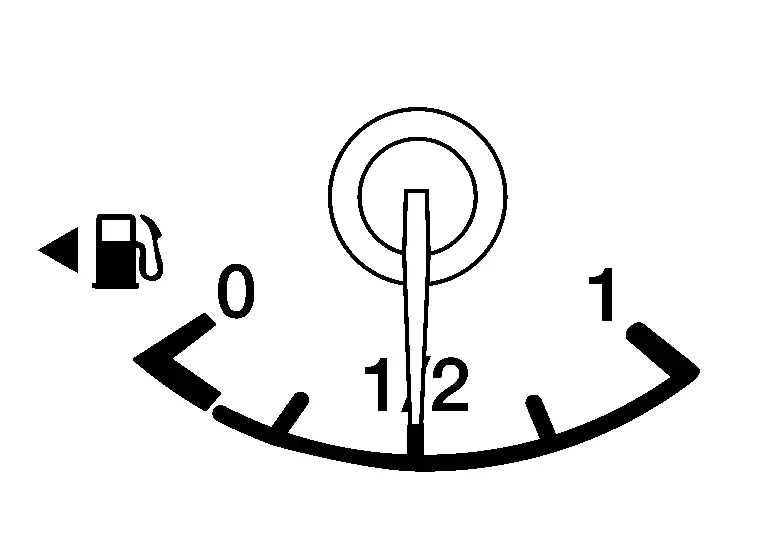
Check the fuel level with the Nissan Pathfinder vehicle on a level surface. If the fuel gauge indicates more than the level as shown (1/2 full), drain the fuel from the fuel tank until the fuel gauge indicates a level at or below as shown (1/2 full).
-
In case the fuel pump does not operate, use the following procedure.
-
As a guide, if the fuel tank is full, drain approximately 35
 (9-1/4 US gal, 7-3/4 Imp gal) to reach 1/2 full or less.
Release fuel pressure from fuel line. Refer to Work Procedure.
Disconnect the battery negative terminal. Refer to Battery disconnect.
Remove second row seat (LH). Refer to Removal and Installation.
Position and secure the carpet to gain access to the fuel pump inspection hole cover.
CAUTION:
Cover the immediate area surrounding the fuel pump inspection hole cover with plastic to avoid gasoline damage to the carpet.
Turn the four retainers (A) 90 degrees to disengage the clips and remove the fuel pump inspection hole cover.
 |
: Front |
Disconnect the fuel level sensor unit, fuel filter, and fuel pump assembly harness connector (C) and the fuel feed hose connector (B) from the fuel level sensor unit, fuel filter, and fuel pump assembly.

| (A) | : EVAP vent tube |
-
Disconnect the quick connector as follows:

-
Hold the sides of the connector, push in tabs (A) and pull out the tube.
-
If the connector and the tube are stuck together, push and pull several times until they start to move. Then disconnect them by pulling.
-
CAUTION:
-
Quick connector (1) can be disconnected when the tabs (F) are depressed completely. Do not twist it more than necessary.

(B) : Connection (cross section)
(D) : To under floor fuel line
(E) : To fuel tank.
(G) : Disconnection
-
Do not use any tools to disconnect quick connector.
-
Keep the resin tube (C) away from heat. Be especially careful when welding near the tube.
-
Prevent acid liquid such as battery electrolyte, etc. from getting on the resin tube.
-
Do not bend or twist the tube during installation and removal.
-
Do not remove the remaining retainer (2) on hard tube or the equivalent (A) except when resin tube or retainer is replaced.
-
When resin tube or hard tube (or the equivalent is replaced, also replace the retainer with a new one.
-
To keep the connecting portion clean and to avoid damage and foreign materials, cover them completely with plastic bags (A) or something similar.
Remove the floor under cover (LH). Refer to Removal and Installation.
Remove the EVAP vent tube from the EVAP canister.
Remove bolts and remove the rear exhaust tube heat shield.
Remove nuts securing rear propeller shaft assembly at center bearing. Refer to Exploded View.
Remove nuts and release metal clips and remove fuel tank protector from the fuel tank.
Remove the bolts and the outer reinforcement bar (if equipped).
Loosen clamp and remove the fuel filler hose from the fuel tank.
Disconnect the EVAP tube quick connector from the fuel filler tube (For USA and Canada models only).
Release clamp and remove EVAP hose from fuel filler tube (For Mexico models only).
Support the center part of the fuel tank using a suitable jack.
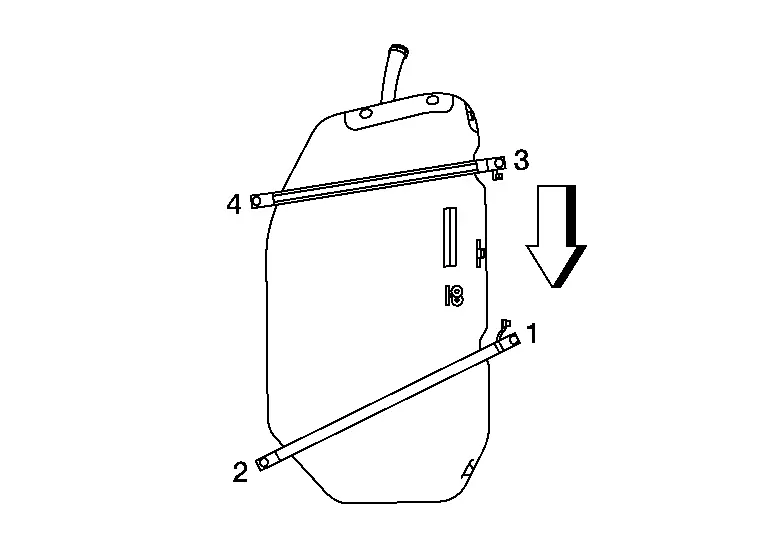
Remove fuel tank mounting strap bolts in reverse of the sequence shown while supporting the fuel tank with a suitable jack and remove fuel tank.

 NOTE:
NOTE:
The fuel tank and fuel tank mounting straps will be removed from the Nissan Pathfinder vehicle as an assembly.
 |
: Front |
Lower suitable jack carefully to remove the fuel tank.
CAUTION:
Fuel tank may be in an unstable condition, due to the shape of the fuel tank bottom. Be sure to secure tank at all times.
If replacing the fuel tank, remove the fuel level sensor unit, fuel filter and fuel pump assembly to transfer to the new fuel tank using the following procedure:Remove the lock ring using Tool.
| Tool number |
: — (NI-45722) : KV101207S0 ( — ) |
| (C) | : Retainer pawl |

CAUTION:
Do not pull on the transfer tube or damage to the fuel tank can occur.
Remove the fuel level sensor unit, fuel filter, and fuel pump assembly and O-ring. Discard the O-ring.CAUTION:
-
Do not bend the float arm during removal.
-
Do not reuse O-ring.
INSTALLATION
Installation is in the reverse order of removal.
-
Tighten the fuel tank mounting strap bolts to the specified torque in the sequence shown.
Fuel tank mounting strap bolts : 40 N·m (4.1 kg-m, 30 ft-lb) 
: Front -
When installing fuel filler hose clamp (fuel tank side), the clamp should be positioned on paint mark located on fuel filler hose.
-
For USA and Canada models, tighten fuel filler hose clamp (fuel tank side) until bolt head is located on paint mark of band.
-
For Mexico models, tighten the fuel filler hose clamp (fuel tank side) to the specified torque.
Clamp : 24.5 N·m (2.5 kg-m, 18 ft-lb)  NOTE:
NOTE:
When tightening clamp (1), verify dimension shown (A) is within range.
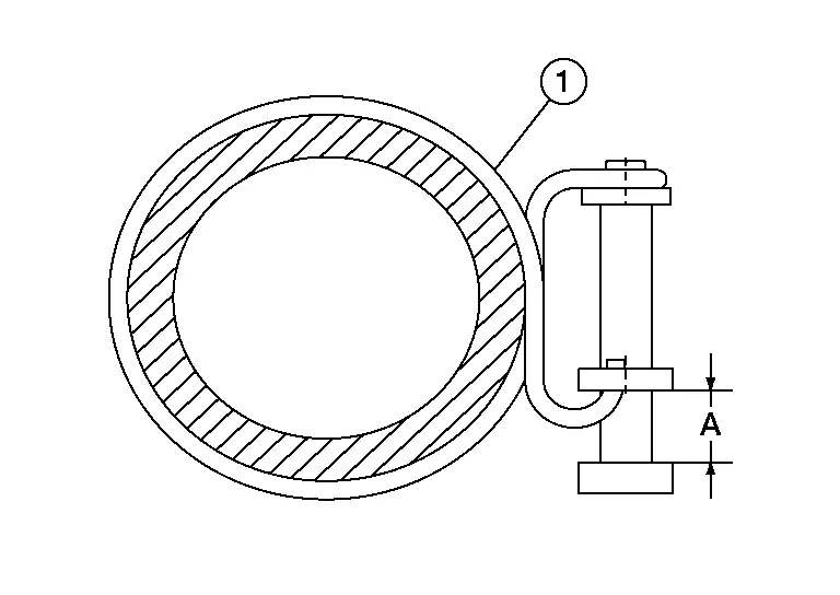
Dimension (A) : 5 – 9 mm (0.20 – 0.35 in) -
If fuel tank has been replaced, install the fuel level sensor unit, fuel filter, and fuel pump assembly using the following procedure:
-
Connect the transfer tube (A) to the fuel level sensor unit, fuel filter, and fuel pump assembly.

-
Install a new O-ring on to fuel tank and install the fuel level sensor unit, fuel filter, and fuel pump assembly.
CAUTION:
-
Make sure that the transfer hose does not interfere with the float arm assembly.
-
Do not reuse O-ring.
-
-
Align the tabs (A) of the fuel level sensor unit, fuel filter, and fuel pump assembly to the matching marks (B) of the fuel tank for proper installation.

(C) : Retainer pawl -
Install lock ring and turn clockwise using Tool.
Tool number : — (NI-45722)
: KV101207S0 ( — )
-
-
Connect the quick connector as follows:
-
Check the connection for damage or any foreign materials.
-
Align the connector with the tube, then insert the connector straight into the tube until a click is heard.
-
-
After the tube is connected, make sure the connection is secure by performing the following checks:
-
Pull the tube and the connector to make sure they are securely connected.
-
Visually confirm that the two retainer tabs (3) are connected to the quick connector (2).
(1): Resin tube
(4): Retainer
(A): Connection (cross-section)
(B): Disconnection
(C): To under floor fuel line
(D): To fuel tank
-
INSPECTION AFTER INSTALLATION
Use the following procedure to check for fuel leaks.
With the ignition in the ON position (without starting the engine) to apply fuel pressure to the fuel system, then check the connections for fuel leaks.
Start engine, raise idle and verify there are no leaks at the fuel system connections.
Evap Canister Nissan Pathfinder R53
Exploded View
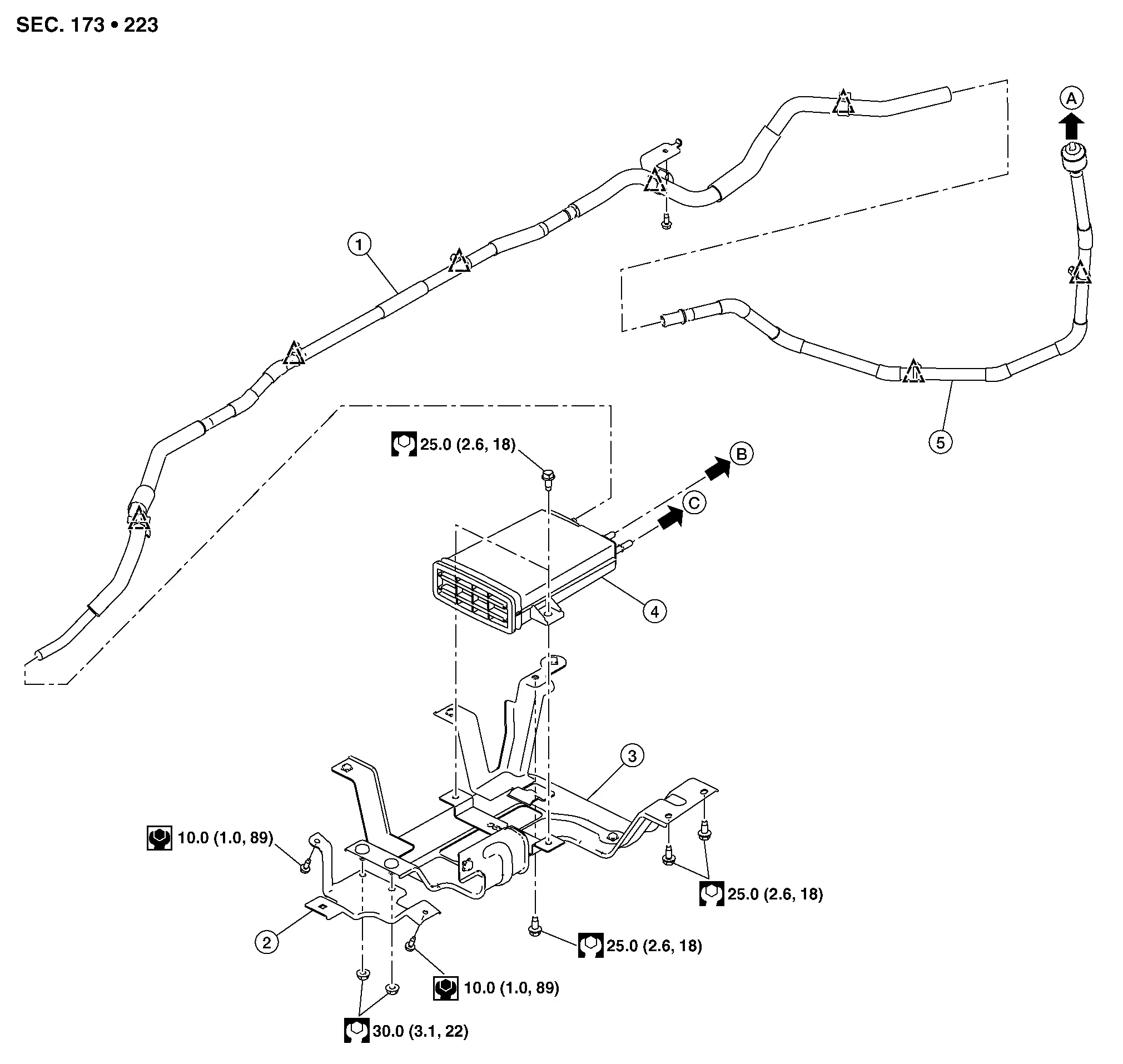
For USA and Canada
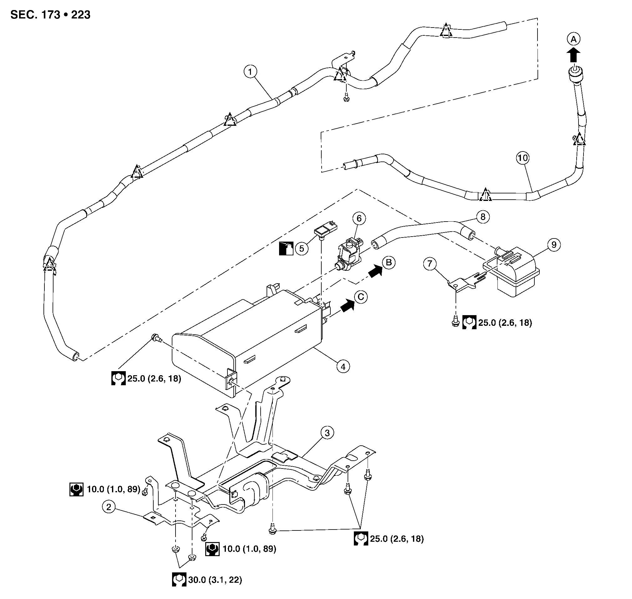
| 1. | EVAP canister filter hose | 2. | EVAP canister bracket A | 3. | EVAP canister bracket B |
| 4. | EVAP canister | 5. | EVAP control system pressure sensor | 6. | EVAP canister vent control valve |
| 7. | EVAP canister vent control valve bracket | 8. | EVAP canister vent control valve hose | 9. | EVAP canister filter |
| 10. | EVAP canister filter hose | A. | To fuel filler tube. Refer to Exploded View. | B. | To EVAP vent tube. Refer to Exploded View. |
| C. | To EVAP vacuum delay valve. Refer to Exploded View. |
 |
Clip |
For Mexico
| 1. | EVAP canister hose | 2. | EVAP canister bracket A | 3. | EVAP canister bracket B |
| 4. | EVAP canister | 5. | EVAP canister hose | A. | To fuel filler tube. Refer to Exploded View. |
| B. | To EVAP vent tube. Refer to Exploded View. | C. | To EVAP vacuum delay valve. Refer to Exploded View. |
 |
Clip |
Removal and Installation
For USA and Canada
 NOTE:
NOTE:
The EVAP canister vent control valve and EVAP canister control system pressure sensor can be removed without removing the EVAP canister.
REMOVAL
Remove the floor under cover (LH). Refer to Removal and Installation.
Disconnect the harness connectors from EVAP canister control pressure sensor and the EVAP canister vent control valve.
Remove the EVAP canister purge hose, the EVAP vent tube and the EVAP canister vent control valve hose.
Remove nuts securing EVAP canister bracket A to EVAP canister bracket B.
Remove EVAP canister bracket bolts and remove EVAP canister bracket and EVAP canister.
Remove bolt securing EVAP canister to EVAP canister bracket and remove EVAP canister.
Remove the EVAP canister vent control valve and EVAP canister control system pressure sensor from EVAP canister (if necessary).
CAUTION:
Do not reuse EVAP canister vent control valve O-ring (if removed).
INSTALLATION
Installation is in the reverse order of removal.
CAUTION:
Do not reuse EVAP canister vent control valve O-ring (if removed).
For Mexico
REMOVAL
Remove the floor under cover (LH). Refer to Removal and Installation.
Remove the EVAP canister hoses from the EVAP canister.
Remove nuts securing EVAP canister bracket A to EVAP canister bracket B.
Remove EVAP canister bracket bolts and remove EVAP canister bracket and EVAP canister.
Remove bolt securing EVAP canister to EVAP canister bracket and remove EVAP canister.
INSTALLATION
Installation is in the reverse order of removal.
Inspection
Check EVAP canister as follows:
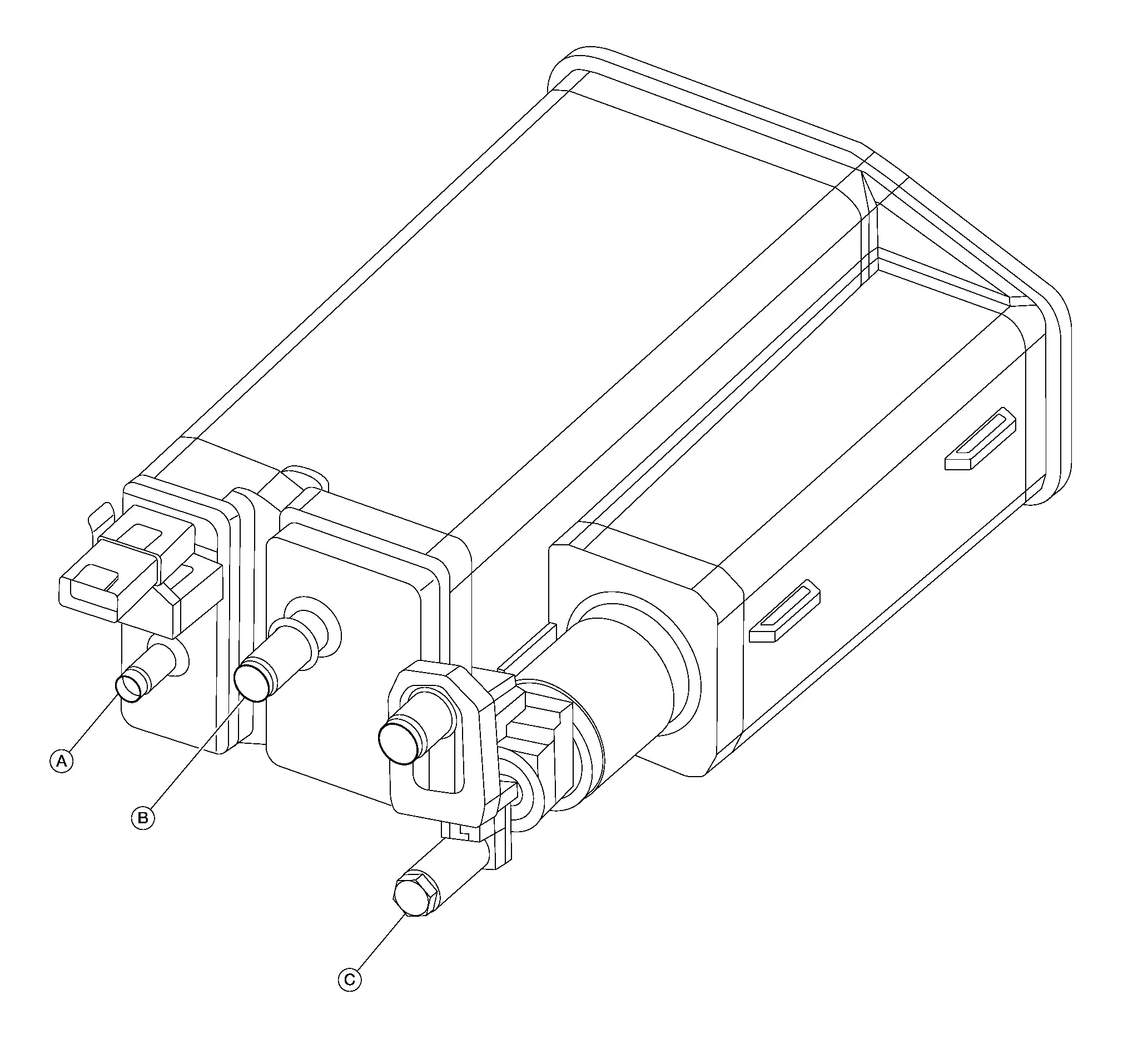
Block port (A).
Blow air into port (B) and check that it flows freely out of port (C).
Release blocked port (A).
Apply vacuum pressure to port (A) and check that vacuum pressure exists at the ports (B) and (C).
Block port (B) and (A).
Apply pressure to port (C) and check that there is no leakage.
Evap Canister Filter Nissan Pathfinder Fifth generation
Exploded View

| 1. | EVAP canister filter hose | 2. | EVAP canister bracket A | 3. | EVAP canister bracket B |
| 4. | EVAP canister | 5. | EVAP control system pressure sensor | 6. | EVAP canister vent control valve |
| 7. | EVAP canister vent control valve bracket | 8. | EVAP canister vent control valve hose | 9. | EVAP canister filter |
| 10. | EVAP canister filter hose | A. | To fuel filler tube. Refer to Exploded View. | B. | To EVAP vent tube. Refer to Exploded View. |
| C. | To EVAP vacuum delay valve. Refer to Exploded View. |
 |
Clip |
Removal and Installation
REMOVAL
Remove the floor under cover (LH). Refer to Removal and Installation.
Remove EVAP canister vent control valve hose from EVAP canister filter.
Remove EVAP canister filter hose from EVAP canister filter.
Remove the bolt and remove the EVAP canister filter and EVAP canister filter bracket.
Remove the EVAP canister filter from the EVAP canister filter bracket (if necessary).
INSTALLATION
Installation is in the reverse order of removal.
Evap Canister Vent Control Valve Nissan Pathfinder
Exploded View

| 1. | EVAP canister filter hose | 2. | EVAP canister bracket A | 3. | EVAP canister bracket B |
| 4. | EVAP canister | 5. | EVAP control system pressure sensor | 6. | EVAP canister vent control valve |
| 7. | EVAP canister vent control valve bracket | 8. | EVAP canister vent control valve hose | 9. | EVAP canister filter |
| 10. | EVAP canister filter hose | A. | To fuel filler tube. Refer to Exploded View. | B. | To EVAP vent tube. Refer to Exploded View. |
| C. | To EVAP vacuum delay valve. Refer to Exploded View. |
 |
Clip |
Removal and Installation
REMOVAL
Remove the floor under cover (LH). Refer to Removal and Installation.
Remove EVAP canister vent control valve hose from EVAP canister vent control valve.
Disconnect the harness connector from EVAP canister vent control valve.
Turn EVAP canister vent control valve (1) counterclockwise.
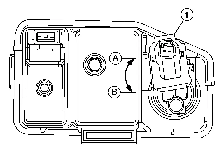
| (A) | : Lock |
| (B) | : Unlock |
Remove the EVAP canister vent control valve and O-ring.
CAUTION:
Do not reuse O-ring.
INSTALLATION
Installation is in the reverse order of removal.
CAUTION:
-
Do not reuse O-ring for EVAP canister vent control valve.
-
Do not add lubrication to the O-ring.
-
Make sure the surfaces that the O-ring comes in contact with are clean.
-
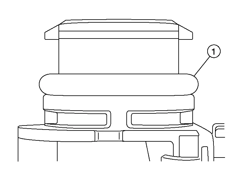
Make sure the O-ring is not twisted or rolled over.
-
Make sure the O-ring (1) is seated all the way down with no gap as shown.
Evap Control System Pressure Sensor Nissan Pathfinder 2022
Exploded View

| 1. | EVAP canister filter hose | 2. | EVAP canister bracket A | 3. | EVAP canister bracket B |
| 4. | EVAP canister | 5. | EVAP control system pressure sensor | 6. | EVAP canister vent control valve |
| 7. | EVAP canister vent control valve bracket | 8. | EVAP canister vent control valve hose | 9. | EVAP canister filter |
| 10. | EVAP canister filter hose | A. | To fuel filler tube. Refer to Exploded View. | B. | To EVAP vent tube. Refer to Exploded View. |
| C. | To EVAP vacuum delay valve. Refer to Exploded View. |
 |
Clip |
Removal and Installation
REMOVAL
Remove the floor under cover (LH). Refer to Removal and Installation.
Disconnect the harness connector from EVAP canister control pressure sensor.
Remove EVAP canister control pressure sensor and O-ring.
INSTALLATION
Installation is in the reverse order of removal.
CAUTION:
Do not reuse O-ring when installing new EVAP canister control pressure sensor. The EVAP canister control pressure sensor and O-ring are serviced as an assembly.
Evap Canister Volume Control Solenoid Valve Nissan Pathfinder 5th Gen
Exploded View
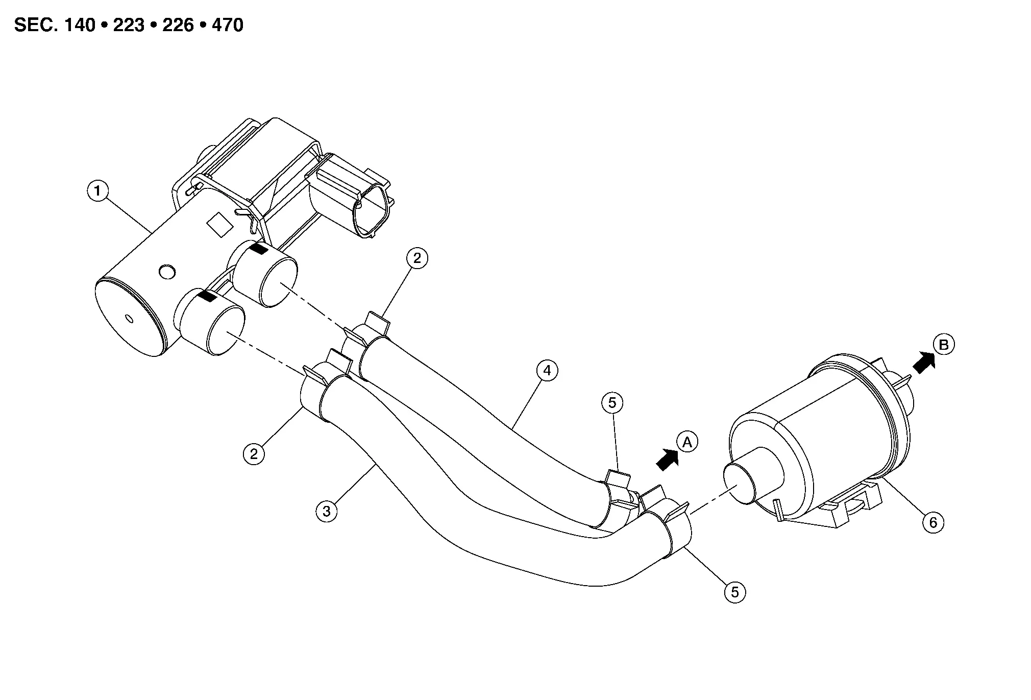
| 1. | EVAP canister purge volume control solenoid valve | 2. | Clamp | 3. | EVAP hose A |
| 4. | EVAP hose B | 5. | Clamp | 6. | EVAP vacuum delay valve |
| A. | To intake manifold fitting. Refer to Exploded View. | B. | To EVAP canister. Refer to Exploded View. |
Removal and Installation
REMOVAL
Remove engine cover. Refer to Removal and Installation.
Disconnect harness connector from EVAP canister purge volume control solenoid valve.
Release clamps and remove EVAP hose A and EVAP hose B from EVAP canister purge volume control solenoid valve.
Remove nut then remove EVAP canister purge volume control solenoid valve.
INSTALLATION
Installation is in the reverse order of removal.
 NOTE:
NOTE:
-
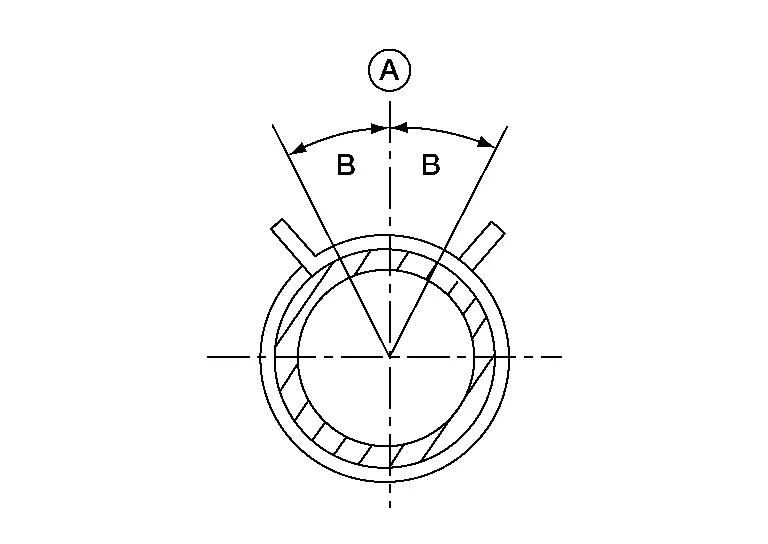
Install EVAP hose paint marks and hose clamp pawls facing up.
-
The angle (B) created by the hose clamp pawl and the EVAP hose paint mark (A) must be within ±15° as shown in the figure.
-
To install hose clamps (1), check that the dimension (A) from the end of the EVAP hose to the hose clamp is within the reference value.
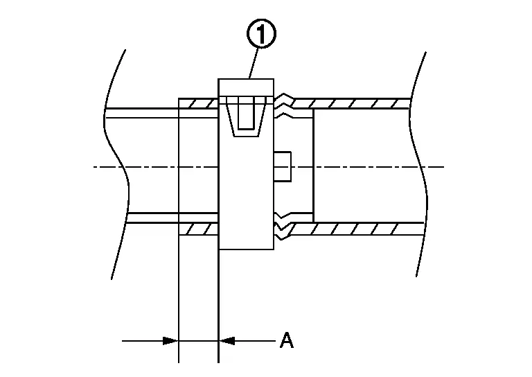
(A) : 2 mm (0.08 in)

Nissan Pathfinder (R53) 2022-2026 Service Manual
Removal and Installation
- Fuel Level Sensor Unit, Fuel Filter and Fuel Pump Assembly
- Fuel Tank
- Evap Canister
- Evap Canister Filter
- Evap Canister Vent Control Valve
- Evap Control System Pressure Sensor
- Evap Canister Volume Control Solenoid Valve
Contact Us
Nissan Pathfinder Info Center
Email: info@nipathfinder.com
Phone: +1 (800) 123-4567
Address: 123 Pathfinder Blvd, Nashville, TN 37214, USA
Working Hours: Mon–Fri, 9:00 AM – 5:00 PM (EST)
