Nissan Pathfinder: Engine Cooling System - Removal and Installation
- Radiator
- Cooling Fan
- Cooling Fan Control
- Water Pump
- Thermostat and Thermostat Housing
- Water Outlet and Water Piping
Radiator Nissan Pathfinder 2022
Exploded View
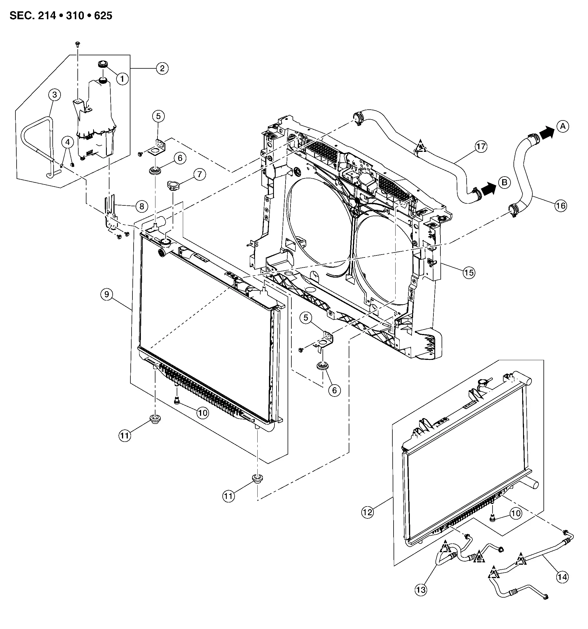
| 1. | Reservoir tank cap | 2. | Reservoir tank assembly | 3. | Reservoir tank hose |
| 4. | Clamp | 5. | Radiator bracket | 6. | Mounting rubber (upper) |
| 7. | Radiator cap | 8. | Reservoir tank bracket | 9. | Radiator (with A/T fluid cooler |
| 10. | Water drain cock | 11. | Mounting rubber (lower) | 12. | Radiator (without A/T fluid cooler) |
| 13. | A/T fluid cooler hose B | 14. | A/T fluid cooler hose A | 15. | Radiator core support |
| 16. | Radiator hose (lower) | 17. | Radiator hose (upper) | A. | To thermostat assembly (water inlet). Refer to Exploded View. |
| B. | To water outlet. Refer to Exploded View. |
Removal and Installation
WITH TOW PACKAGE
WARNING:
-
Do not remove the radiator cap or reservoir tank cap when the engine is hot. Serious burns could occur from high-pressure engine coolant escaping from the cooling system.
-
When removing the radiator cap or reservoir tank cap, wrap a thick cloth around the cap and slowly turn it a quarter turn to allow built-up pressure to escape. Then carefully remove the cap by turning it all the way.
 NOTE:
NOTE:
-
When removing components such as hoses, tubes/lines, etc., cap or plug openings to prevent fluid from spilling.
-
The radiator hose clamps on the radiator hose (upper) and on the radiator hose (lower), are not serviced separately. Radiator hose clamps are part of the radiator hose assembly and serviced as one unit with the radiator hose.
REMOVAL
Drain engine coolant from radiator. Refer to Draining.
CAUTION:
-
Perform this step when the engine is cold.
-
Do not spill engine coolant on the drive belt.
Remove the radiator hose (lower) from the radiator.
 NOTE:
NOTE:
The radiator hose clamps on the radiator hose (upper) are not serviced separately. Radiator hose clamps are part of the radiator hose assembly and serviced as one unit with the radiator hose.
Remove the active grille shutter. Refer to Removal and Installation.
Disconnect the harness connector from the horn (HIGH).
Remove the front fascia reinforcement (upper). Refer to Exploded View.
Remove the condenser pipe assembly.
Disconnect the harness connector from the refrigerant pressure sensor.
Remove the condenser. Refer to Exploded View.
Remove the reservoir tank hose from the radiator.
Disconnect radiator hose (upper) from the radiator.
CAUTION:
Do not allow the engine coolant to contact the drive belt.
 NOTE:
NOTE:
The radiator hose clamps on the radiator hose (upper) are not serviced separately. Radiator hose clamps are part of the radiator hose assembly and serviced as one unit with the radiator hose.
Remove the radiator mounts (upper).
Remove radiator.
CAUTION:
Do not damage or scratch the radiator core when removing.
INSTALLATION
Installation is in the reverse order of removal.
CAUTION:
Do not reuse O-ring.
-
After installation, perform the following:
-
Refill the engine coolant, refer to Refilling.
CAUTION:
Do not spill engine coolant in engine compartment. Use a shop cloth to absorb engine coolant.
-
Check cooling system for leaks, refer to System Inspection.
-
WITHOUT TOW PACKAGE
WARNING:
-
Do not remove the radiator cap or reservoir tank cap when the engine is hot. Serious burns could occur from high-pressure engine coolant escaping from the cooling system.
-
When removing the radiator cap or reservoir tank cap, wrap a thick cloth around the cap and slowly turn it a quarter turn to allow built-up pressure to escape. Then carefully remove the cap by turning it all the way.
 NOTE:
NOTE:
-
When removing components such as hoses, tubes/lines, etc., cap or plug openings to prevent fluid from spilling.
-
The radiator hose clamps on the radiator hose (upper) and on the radiator hose (lower), are not serviced separately. Radiator hose clamps are part of the radiator hose assembly and serviced as one unit with the radiator hose.
REMOVAL
Drain engine coolant from radiator. Refer to Draining.
CAUTION:
-
Perform this step when the engine is cold.
-
Do not spill engine coolant on the drive belt.
Remove the radiator hose (lower) from the radiator.
 NOTE:
NOTE:
The radiator hose clamps on the radiator hose (upper) are not serviced separately. Radiator hose clamps are part of the radiator hose assembly and serviced as one unit with the radiator hose.
Remove the active grille shutter. Refer to Removal and Installation.
Disconnect the harness connector from the horn (HIGH).
Remove the front fascia reinforcement (upper). Refer to Exploded View.
Remove the A/T fluid cooler hose cap (1) from A/T fluid cooler hose A (2) and A/T fluid cooler hose B (2).

Install suitable tool (A) onto the A/T fluid cooler hose A and A/T fluid cooler hose B at the radiator.
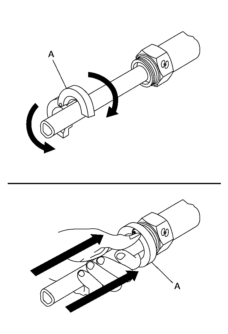
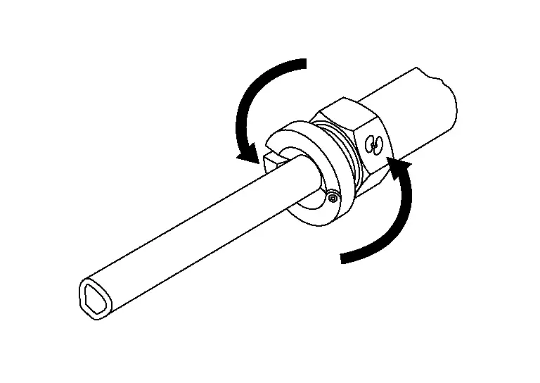
Rotate suitable tool counterclockwise 60 degrees to release snap ring.
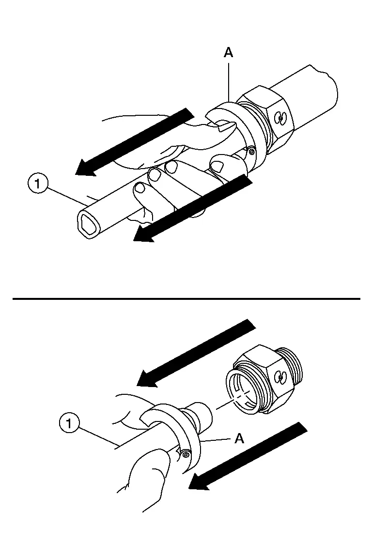
Remove A/T fluid cooler hose A (1) and A/T fluid cooler hose B (1) from the radiator.
Remove the condenser pipe assembly.
Disconnect the harness connector from the refrigerant pressure sensor.
Remove the condenser. Refer to Exploded View.
Remove the reservoir tank hose from the radiator.
Disconnect radiator hose (upper) from the radiator.
CAUTION:
Do not allow the engine coolant to contact the drive belt.
 NOTE:
NOTE:
The radiator hose clamps on the radiator hose (upper) are not serviced separately. Radiator hose clamps are part of the radiator hose assembly and serviced as one unit with the radiator hose.
Remove the radiator mounts (upper).
Remove radiator.
CAUTION:
Do not damage or scratch the radiator core when removing.
INSTALLATION
Installation is in the reverse order of removal.
CAUTION:
Do not reuse O-ring.
-
After installation, perform the following:
-
Refill the engine coolant, refer to Refilling.
CAUTION:
Do not spill engine coolant in engine compartment. Use a shop cloth to absorb engine coolant.
-
Check cooling system for leaks, refer to System Inspection.
-
Refill the A/T fluid and check for leaks, refer to Adjustment (ADJUSTMENT) and Inspection (INSPECTION).
-
Cooling Fan Nissan Pathfinder 2026
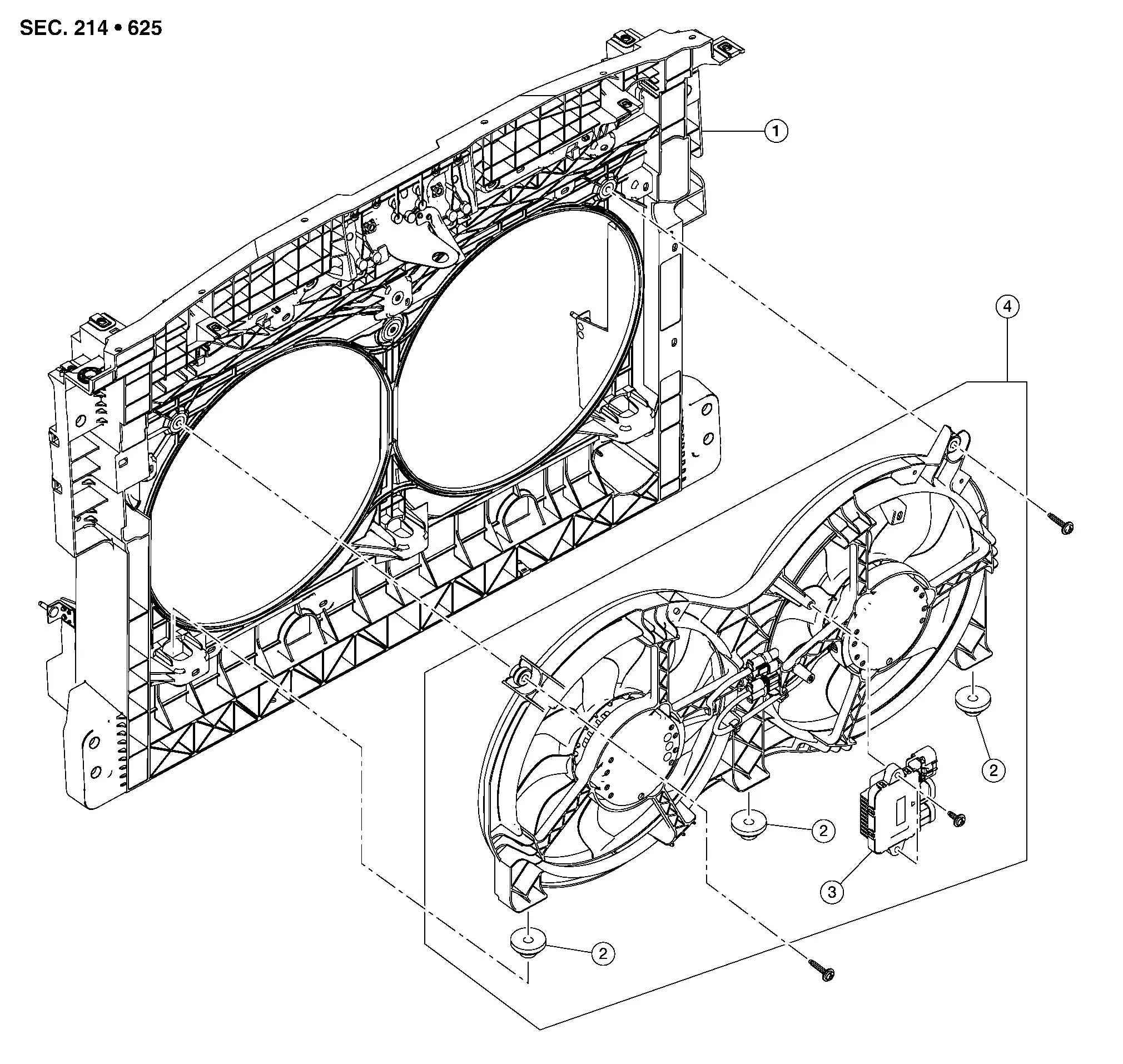
Exploded View

| 1. | Radiator core support | 2. | Grommet | 3. | Cooling fan control module |
| 4. | Cooling fan assembly |
Removal and Installation
 NOTE:
NOTE:
Replace the cooling fan motor assembly as a unit.
REMOVAL
Recycle the refrigerant. Refer to Recycle Refrigerant.
Partially drain the engine coolant. Refer to Draining.
Remove engine room cover. Refer to Removal and Installation.
Remove air inlet duct. Refer to Exploded View.
Remove battery and battery tray. Refer to Removal and Installation.
Disconnect the harness connector from cooling fan control module and remove harness retainer from fan shroud and motor assembly.
Remove cooling fan control module.
Remove the radiator hose (upper) from the radiator.
Release the radiator hose (upper) retainer and reposition the radiator hose (upper).
Remove the low-pressure flexible hose. Refer to Exploded View.
Remove the high-pressure flexible hose from the condenser. Refer to Exploded View.
Remove the high-pressure pipe. Refer to Exploded View.
Remove the ground cable from the engine assembly.
Remove the engine oil level gauge.
Remove the high-pressure fuel pump insulator. Refer to Exploded View.
Remove the bolt securing the coolant reservoir to the radiator core support. Refer to Exploded View.
Remove the coolant over flow hose from the radiator and remove the coolant reservoir and washer tank filler neck as an assembly.
Remove bolts and remove the cooling fan assembly.
INSTALLATION
Installation is in the reverse order of removal.
-
Refill the engine coolant. Refer to Refilling.
-
Charge the refrigerant. Refer to Charge Refrigerant.
Cooling Fan Control Nissan Pathfinder R53
Exploded View
| 1. | Radiator core support | 2. | Grommet | 3. | Cooling fan control module |
| 4. | Cooling fan assembly |
Removal and Installation
REMOVAL
Disconnect the battery. Refer to Battery Disconnect.
Remove the core support cover. Refer to Exploded View.
Remove air cleaner and air duct assembly. Refer to Exploded View.
Disconnect the harness connectors from the cooling fan control module.
Remove the cooling fan control module.
INSTALLATION
Installation is in the reverse order of removal.
Water Pump Nissan Pathfinder SUV
Exploded View
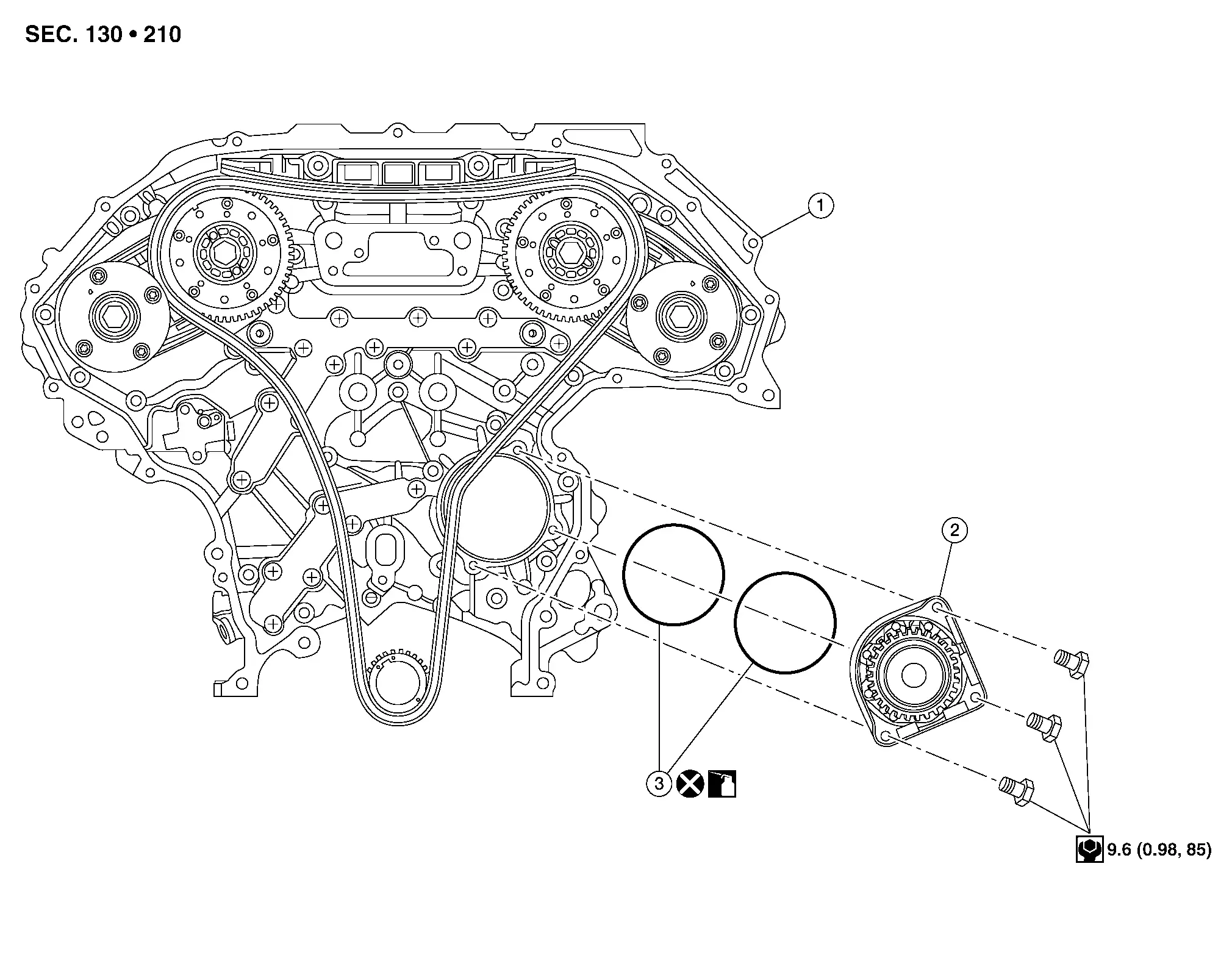
| 1. | Rear timing chain case | 2. | Water pump | 3. | O-ring |
Removal and Installation
WARNING:
-
Do not remove the radiator cap or reservoir tank cap when the engine is hot. Serious burns could occur from high-pressure engine coolant escaping from the cooling system.
-
When removing the radiator cap or reservoir tank cap, wrap a thick cloth around the cap and slowly turn it a quarter turn to allow built-up pressure to escape. Then carefully remove the cap by turning it all the way.
 NOTE:
NOTE:
-
When removing components such as hoses, tubes/lines, etc., cap or plug openings to prevent fluid from spilling.
-
The radiator hose clamps on the radiator hose (upper) and on the radiator hose (lower), are not serviced separately. Radiator hose clamps are part of the radiator hose assembly and serviced as one unit with the radiator hose.
REMOVAL
Remove front timing chain case. Refer to Removal and Installation.
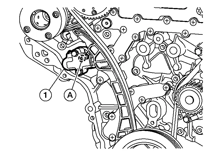
Compress timing chain tensioner [primary (1)] and insert a suitable tool into hole (A).
Remove bolts (A) securing water pump (2).
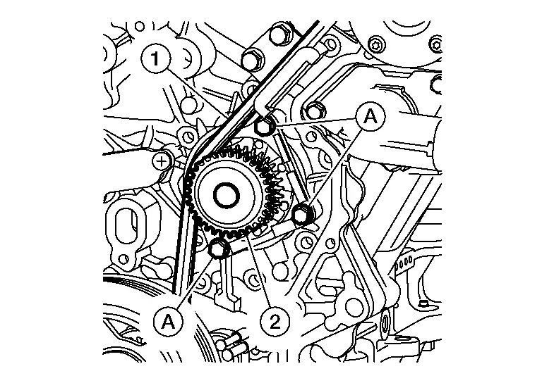
| (1) | : Timing chain (primary) |
Hold timing chain [primary (1)] to the side and remove water pump.
CAUTION:
Do not reuse O-rings.
INSPECTION AFTER REMOVAL
-
Visually check for significant dirt or rust on the water pump body and vane.
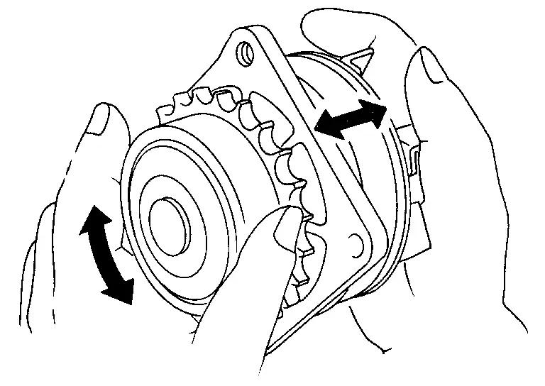
-
Check that the vane shaft turns smoothly by hand and is not excessively loose.
-
Replace the water pump assembly if the water pump does not perform properly.
INSTALLATION
Install new O-rings to water pump (1).
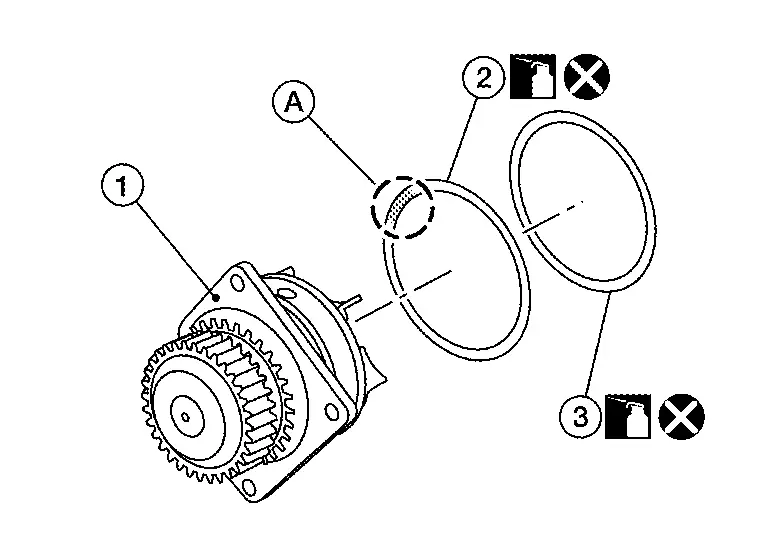
-
Apply engine coolant to O-rings (2,3).
-
Locate O-ring (2) with white paint mark (A) to engine front side.
CAUTION:
Do not reuse O-rings.
Installation of remaining components is in the reverse order of removal.
-
After installation, refill engine coolant and check for leaks. Refer to Refilling (REFILLING) and System Inspection (SYSTEM INSPECTION).
CAUTION:
Do not spill engine coolant in engine compartment. Use a shop cloth to absorb engine coolant.
-
After starting engine, let idle for three minutes, then rev engine up to 3,000 rpm under no load to purge air from the high-pressure chamber of the chain tensioner. The engine may produce a rattling noise. This indicates that air still remains in the chamber and is not a matter of concern.
INSPECTION AFTER INSTALLATION
-
Before starting engine, check oil/fluid levels including engine coolant and engine oil. If less than required quantity, fill to the specified level. Refer to Fluids and Lubricants (FOR USA AND CANADA) or Fluids and Lubricants (FOR MEXICO).
-
Use procedure below to check for fuel leakage.
-
Place ignition switch in the "ON" position (with engine stopped). With fuel pressure applied to fuel piping, check for fuel leakage at connection points.
-
Start engine. With engine speed increased, check again for fuel leakage at connection points.
-
Run engine to check for unusual noise and vibration.
 NOTE:
NOTE:
If hydraulic pressure inside timing chain tensioner drops after removal and installation, slack in the guide may generate a pounding noise during and just after engine start. However, this is normal. Noise will stop after hydraulic pressure rises.
-
Warm up engine thoroughly to make sure there is no leakage of fuel, exhaust gas, or any oils/fluids including engine oil and engine coolant.
-
Bleed air from passages in lines and hoses, such as in cooling system.
-
After cooling down engine, again check oil/fluid levels including engine oil and engine.
Refill to specified level, if necessary.
-
Summary of the inspection items:
Item Before starting engine Engine running After engine stopped Engine coolant Level Leakage Level Engine oil Level Leakage Level Transaxle fluid AT & CVT Models Leakage Level/Leakage Leakage MT Models Level/Leakage Leakage Level/Leakage Other oils and fluids* Level Leakage Level Fuel Leakage Leakage Leakage Exhaust gas — Leakage — *Power steering fluid, brake fluid, etc.
Thermostat and Thermostat Housing Nissan Pathfinder 2026
Exploded View
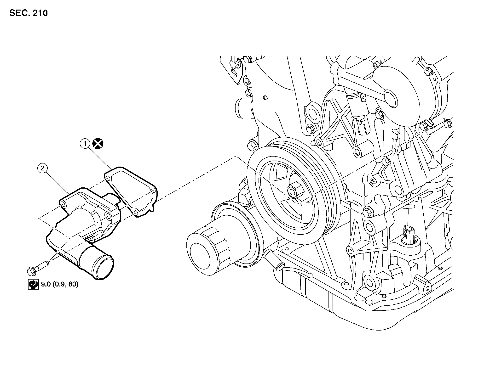
| 1. | Gasket | 2. | Thermostat assembly (water inlet) |
Removal and Installation
WARNING:
Do not remove the reservoir tank cap when the engine is hot. Serious burns could occur from high pressure engine coolant escaping from the reservoir tank. Wrap a thick cloth around the cap. Slowly turn it a quarter turn to allow built-up pressure to escape. Carefully remove the cap by turning it all the way.
 NOTE:
NOTE:
When removing components such as hoses, tubes/lines, etc., cap or plug openings to prevent fluid from spilling.
REMOVAL
Drain engine coolant. Refer to Draining.
CAUTION:
-
Perform when engine is cold.
-
Do not spill engine coolant on the drive belt.
Remove reservoir tank. Refer to Exploded View.
Remove front under cover. Refer to Removal and Installation.
Disconnect the harness connector from intake valve timing control solenoid valve (LH). Refer to Exploded View.
Remove the lower radiator hose.
Remove thermostat assembly (water inlet).
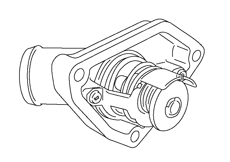
CAUTION:
Do not disassemble thermostat assembly (water inlet). Replace as a unit (if necessary).
INSPECTION AFTER REMOVAL
-
Place a thread so that it is caught in the valves of the thermostat. Immerse fully in a container filled with water. Heat while stirring.
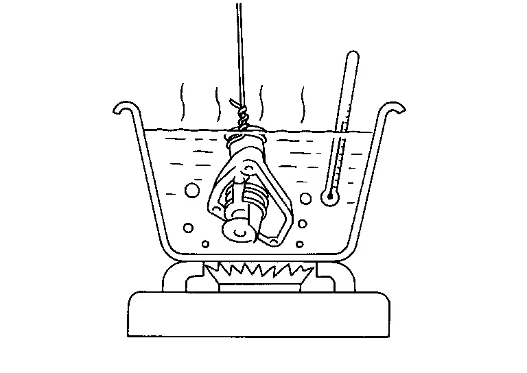
-
The valve opening temperature is the temperature at which the valve opens and the thermostat falls from the thread.
-
Continue heating. Check the full-open lift amount.
 NOTE:
NOTE:
The full-open lift amount standard temperature for the thermostat is the reference value.
-
After checking the full-open lift amount, lower the water temperature and check the valve closing temperature.
Thermostat Standard Values Valve opening temperature Refer to Thermostat Full-open lift amount Refer to Thermostat Valve closing temperature Refer to Thermostat -
If thermostat values are out of standard range, replace water inlet and thermostat assembly.
INSTALLATION
Installation is in the reverse order of removal.
CAUTION:
Do not reuse gasket.
-
After installation, refill engine coolant and check for leaks. Refer to Refilling (REFILLING) and System Inspection (SYSTEM INSPECTION).
CAUTION:
Do not spill engine coolant in engine compartment. Use a shop cloth to absorb engine coolant.
Water Outlet and Water Piping Nissan Pathfinder
Exploded View
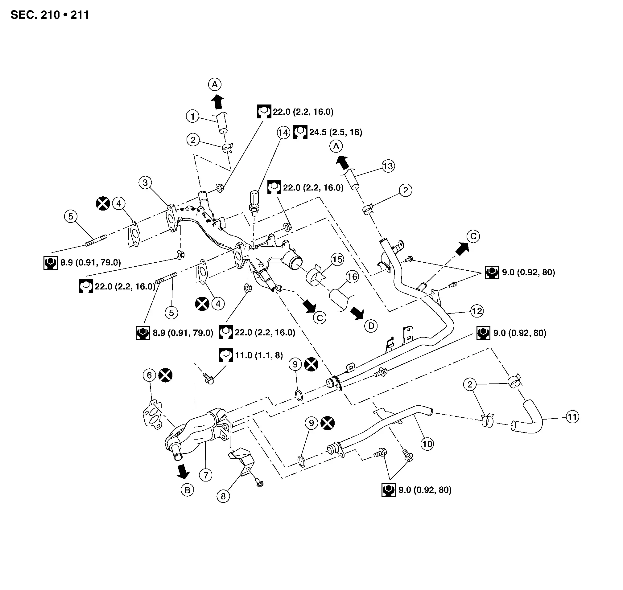
| 1. | Heater hose | 2. | Hose clamp | 3. | Water outlet |
| 4. | Water outlet gasket | 5. | Stud | 6. | Water connector gasket |
| 7. | Water connector | 8. | Engine oil dipstick guide | 9. | O-ring |
| 10. | Water bypass pipe | 11. | Water hose | 12. | Heater pipe |
| 13. | Heater hose | 14. | Coolant temperature sensor | 15. | Hose clamp |
| 16. | Radiator hose (upper) | A. | To heater core. Refer to Exploded View. | B. | To oil cooler. Refer to Exploded View. |
| C. | To A/T fluid warmer. Refer to Exploded View. | D. | To radiator. Refer to Exploded View. |
Removal and Installation
WARNING:
Do not remove the reservoir tank cap when the engine is hot. Serious burns could occur from high pressure engine coolant escaping from the reservoir tank. Wrap a thick cloth around the cap. Slowly turn it a quarter turn to allow built-up pressure to escape. Carefully remove the cap by turning it all the way.
 NOTE:
NOTE:
-
When removing components such as hoses, tubes/lines, etc., cap or plug openings to prevent fluid from spilling.
-
The radiator hose clamps on the radiator hose (upper) and on the radiator hose (lower), are not serviced separately. Radiator hose clamps are part of the radiator hose assembly and serviced as one unit with the radiator hose.
REMOVAL
Partially drain engine coolant from radiator. Refer to Draining.
CAUTION:
-
Perform this step when the engine is cold.
-
Do not spill engine coolant on the drive belt.
Remove engine room cover. Refer to Removal and Installation.
Remove battery. Refer to Removal and Installation.
Remove air cleaner and air duct. Refer to Removal and Installation.
Remove radiator hose (upper) and heater hoses.
Remove heater pipe.
Disconnect the harness connector from the engine coolant temperature sensor.
Remove engine coolant temperature sensor (if necessary).
Remove water outlet.
Remove water connector (if necessary).
 NOTE:
NOTE:
It is necessary to remove engine oil dipstick guide before removing water connector.
INSTALLATION
Installation is in the reverse order of removal.
-
Securely insert each hose, and install a clamp at a position where it does not interfere with the pipe bulge.
CAUTION:
Do not reuse gasket.
-
When inserting heater pipe and water bypass pipe into water connector, apply mild soap to new O-rings.
CAUTION:
Do not reuse O-rings.
-
After installation, refill engine coolant and check for leaks. Refer to Refilling (REFILLING) and System Inspection (SYSTEM INSPECTION).

Nissan Pathfinder (R53) 2022-2026 Service Manual
Removal and Installation
- Radiator
- Cooling Fan
- Cooling Fan Control
- Water Pump
- Thermostat and Thermostat Housing
- Water Outlet and Water Piping
Contact Us
Nissan Pathfinder Info Center
Email: info@nipathfinder.com
Phone: +1 (800) 123-4567
Address: 123 Pathfinder Blvd, Nashville, TN 37214, USA
Working Hours: Mon–Fri, 9:00 AM – 5:00 PM (EST)
