Nissan Pathfinder: Driveline - Rear Propeller Shaft: 3fcj-Cvj
- Precautions
- Preparation
- Symptom Diagnosis. Noise, Vibration and Harshness (nvh) Troubleshooting
- Basic Inspection. Propeller Shaft Assembly
- Removal and Installation. Rear Propeller Shaft
- Service Data and Specifications (SDS)
Precautions Nissan Pathfinder SUV
Precaution for Supplemental Restraint System (SRS) "AIR BAG" and "SEAT BELT PRE-TENSIONER"
The Supplemental Restraint System such as “AIR BAG” and “SEAT BELT PRE-TENSIONER”, used along with a front seat belt, helps to reduce the risk or severity of injury to the driver and front passenger for certain types of collisions.
Information necessary to service the system safely is included in the “SRS AIR BAG” and “SEAT BELT” sections of this Service Manual.
WARNING:
Always observe the following items for preventing accidental activation:
-
To avoid rendering the SRS inoperative, which could increase the risk of personal injury or death in the event of a collision that would result in air bag inflation, it is recommended that all maintenance and repair be performed by an authorized NISSAN/INFINITI dealer.
-
Improper repair, including incorrect removal and installation of the SRS, can lead to personal injury caused by unintentional activation of the system. For removal of Spiral Cable and Air Bag Module, see “SRS AIR BAG”.
-
Never use electrical test equipment on any circuit related to the SRS unless instructed to in this Service Manual. SRS wiring harnesses can be identified by yellow and/or orange harnesses or harness connectors.
PRECAUTIONS WHEN USING POWER TOOLS (AIR OR ELECTRIC) AND HAMMERS
WARNING:
Always observe the following items for preventing accidental activation:
-
When working near the Air Bag Diagnosis Sensor Unit or other Air Bag System sensors with the ignition/power switch ON or engine running, never use air or electric power tools or strike near the sensor(s) with a hammer. Heavy vibration could activate the sensor(s) and deploy the air bag(s), possibly causing serious injury.
-
When using air or electric power tools or hammers, always switch the ignition/power switch OFF, disconnect the 12V battery or batteries, and wait at least 3 minutes before performing any service.
Preparation Nissan Pathfinder 2022
Special Service Tool
The actual shape of the tools may differ from those illustrated here.
|
Tool number (TechMate No.) Tool name | Description | |
|---|---|---|
|
— (NI-53123) Park lock tool |
|
Placing transaxle in neutral |
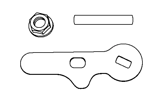
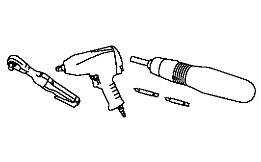
Commercial Service Tool
| Tool name | Description | |
|---|---|---|
| Power tool |
|
Loosening nuts, screws and bolts |
Always Replace with New Parts
| Never Reuse These Parts | Part # Prefix | For additional information: |
|---|---|---|
| Bolt | 37010AA | REAR PROPELLER SHAFT EXPLODED VIEW |
| Nut | 37050B | REAR PROPELLER SHAFT EXPLODED VIEW |
Symptom Diagnosis. Noise, Vibration and Harshness (nvh) Troubleshooting Nissan Pathfinder SUV
NVH Troubleshooting Chart
Use the chart below to find the cause of the symptom. If necessary, repair or replace these parts.
| Possible cause and SUSPECTED PARTS | Symptom | Reference | ||
|---|---|---|---|---|
| Noise | Shake | Vibration | ||
| Uneven rotation torque | X | — | X | Refer to Inspection |
| Center bearing improper installation | X | X | X | Refer to Inspection |
| Excessive center bearing axial end play | X | — | X | — |
| Center bearing mounting (insulator) cracks, damage or deterioration | X | — | X | Refer to Inspection |
| Excessive joint angle | X | X | X | — |
| Rotation imbalance | X | — | X | Refer to Inspection |
| Excessive runout | X | — | X | Refer to Inspection |
| DIFFERENTIAL | X | — | — | Refer to NVH Troubleshooting Chart |
| AXLE AND SUSPENSION | X | X | X |
Refer to NVH Troubleshooting Chart Refer to NVH Troubleshooting Chart Refer to NVH Troubleshooting Chart Refer to NVH Troubleshooting Chart |
| TIRE | X | X | X | Refer to NVH Troubleshooting Chart |
| ROAD WHEEL | X | X | — | Refer to NVH Troubleshooting Chart |
| DRIVE SHAFT | X | X | X |
Refer toNVH Troubleshooting Chart Refer to NVH Troubleshooting Chart |
| BRAKE | X | X | — | Refer to NVH Troubleshooting Chart |
| STEERING | X | X | X | Refer to NVH Troubleshooting Chart |
×: Applicable
Basic Inspection. Propeller Shaft Assembly Nissan Pathfinder R53
Inspection
APPEARANCE AND NOISE INSPECTION
-
Inspect the propeller shaft tube for dents or cracks. If damaged, replace the propeller shaft assembly.
-
Check bearings for noise or damage. If damaged, replace as necessary.
PROPELLER SHAFT VIBRATION
 NOTE:
NOTE:
If vibration is present at high speed, check the propeller shaft runout first, then check mounting between propeller shaft and companion flange.
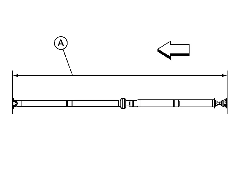
Measure the runout of the propeller shaft tube at several points by rotating the final drive companion flange with your hands.
| Propeller shaft runout | : Refer to Propeller Shaft Runout. |
| A. | Runout measure range |
 |
: Front |

If the runout still exceeds specifications, disconnect the propeller shaft at the final drive companion flange; then rotate the companion flange 90°, 180°, 270° and reconnect propeller shaft.
Check the runout again. If the runout still exceeds specifications, replace the propeller shaft assembly.
After installation, check for vibration by driving the Nissan Pathfinder vehicle.
Removal and Installation. Rear Propeller Shaft Nissan Pathfinder SUV
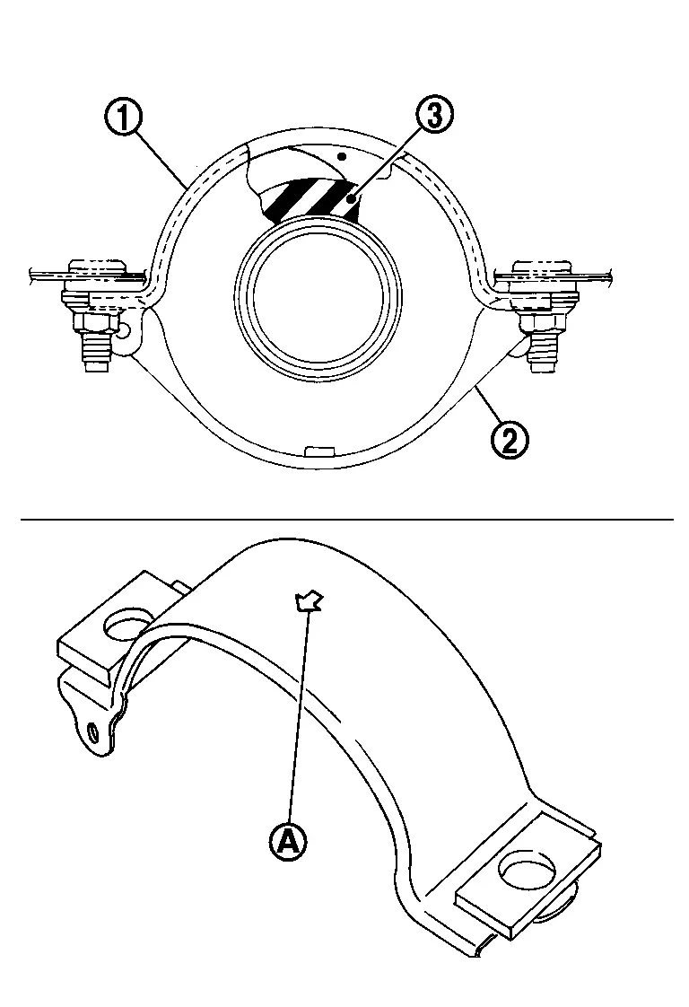
Exploded View
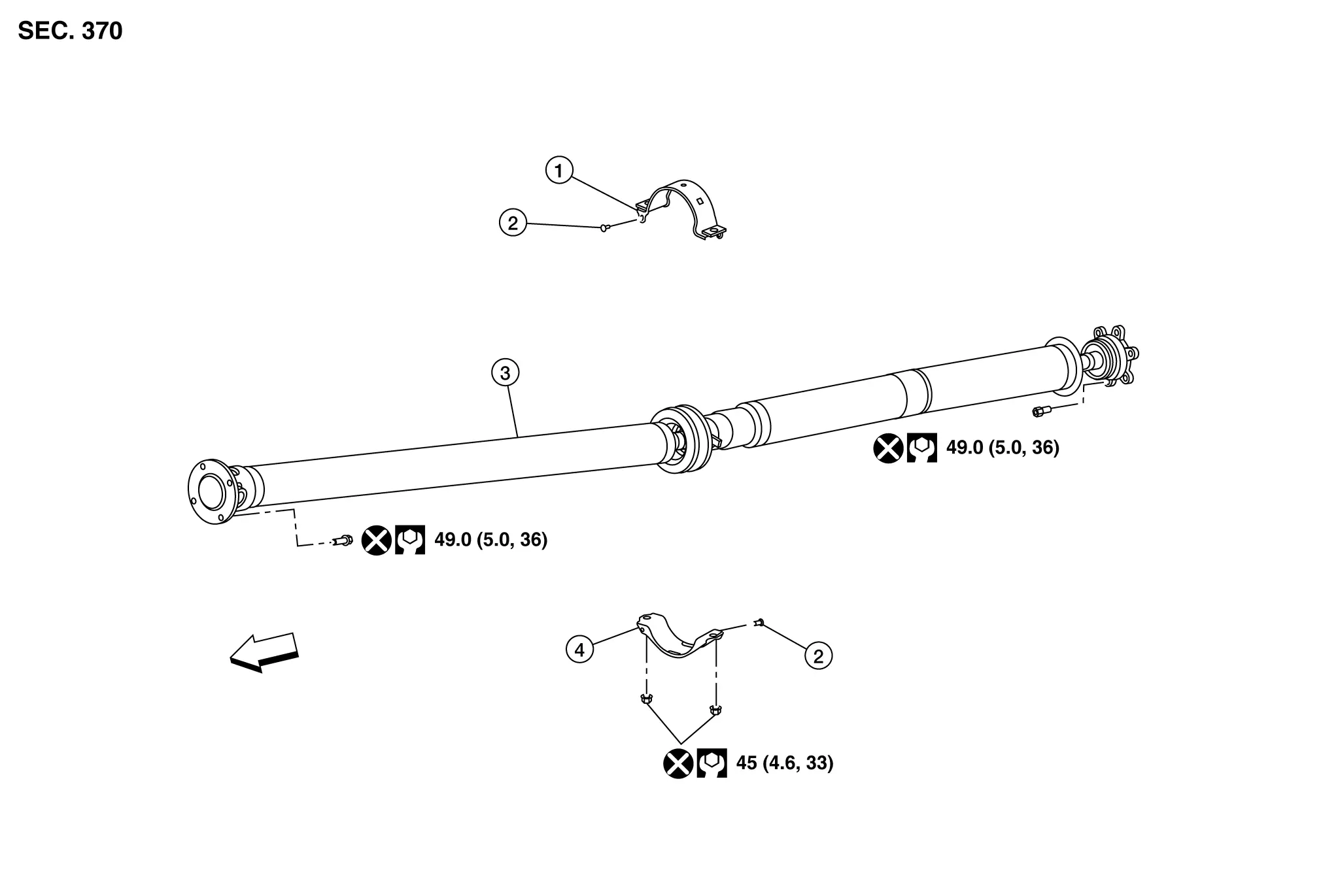
| 1. | Center bearing mounting bracket (upper) | 2. | Clip | 3. | Rear propeller shaft assembly |
| 4. | Center bearing mounting bracket (lower) |
 |
Nissan Pathfinder Vehicle front |
Removal and Installation
REMOVAL
Remove air duct hose and resonator assembly. Refer to Exploded View.
Use Tool (A) to place transaxle assembly (1) in neutral position.
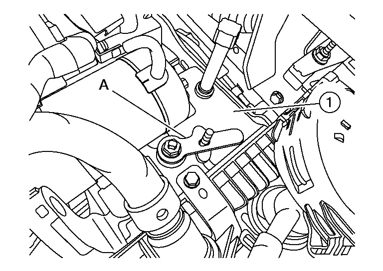
| Tool (A) | : — (NI-53123) |
Remove front heat insulator.
Put matching marks onto propeller shaft flange yoke and transfer companion flange.
CAUTION:
For matching marks, use paint. Do not damage propeller shaft flange yokes or transfer companion flange.
Put matching marks onto propeller shaft flange yokes or electro-hydraulic coupling companion flange.
CAUTION:
For matching marks, use paint. Do not damage propeller shaft flange yokes or electro-hydraulic coupling companion flange.
Loosen the nuts of center bearing mounting brackets (upper/lower).
 |
: Front |
Remove propeller shaft assembly bolts from the transfer assembly side. Refer to Exploded View.
Remove propeller shaft assembly bolts from the rear final drive assembly side. Refer to Exploded View.
Remove center bearing mounting bracket nuts.
CAUTION:
Do not reuse nuts.
Remove propeller shaft assembly.
CAUTION:
If constant velocity joint was bent during propeller shaft assembly removal, installation, or transportation, its boot may be damaged. Wrap boot with shop cloth or rubber to protect boot from damage.
Remove clips in the center bearing mounting bracket (upper/lower).
Perform inspection after removal. Refer to Inspection.
INSTALLATION
Installation is in the reverse order of removal.
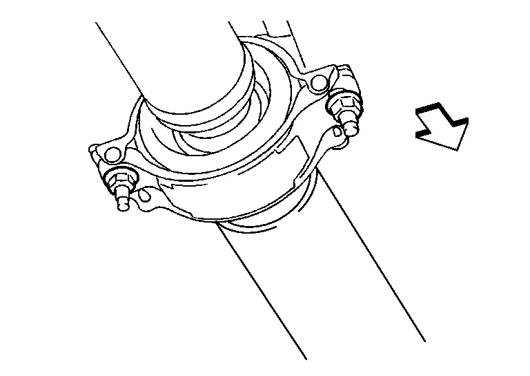
-
Install center bearing mounting bracket [upper (1)] with its arrow mark (A) facing forward.
-
Adjust the position of the center bearing mounting bracket (upper), center bearing mounting bracket [lower (2)] sliding back and forth to prevent play in thrust direction of center bearing insulator (3). Install center bearing mounting bracket (upper/lower) to Nissan Pathfinder vehicle.
-
Align matching marks to install propeller shaft assembly to final drive and transfer companion flanges.
-
Perform inspection after installation. Refer to Inspection.
-
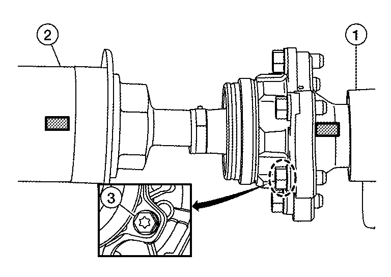
After tightening the bolts and nuts to the specified torque, check that the bolts (3) on the flange side are tightened as shown.
-
Final drive assembly (1)
-
Propeller shaft assembly (2)
-
-
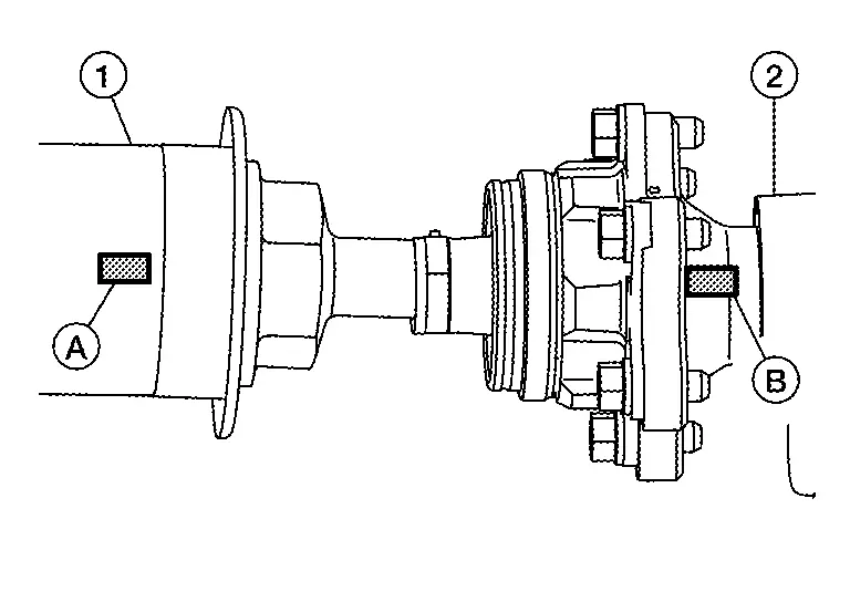
If propeller shaft assembly or final drive assembly has been replaced, connect them as follows:
-
Install propeller shaft (1) while aligning its matching mark (A) with the matching mark (B) of the final drive (2) on the joint as close as possible.
-
Tighten bolts and nuts of propeller shaft and final drive to the specified torque.
-
Inspection
Inspection after removal
Appearance
Check propeller shaft for bend and damage. If damage is detected, replace propeller shaft assembly.
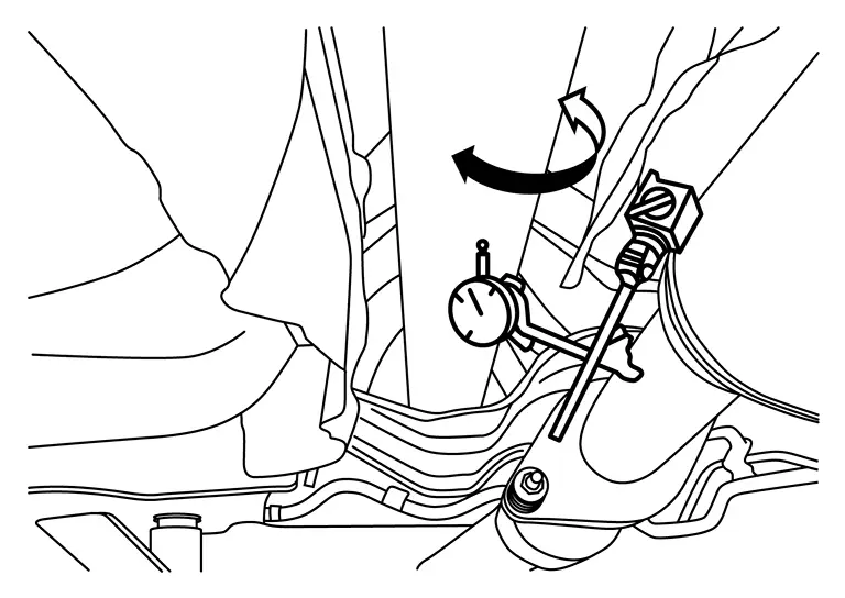
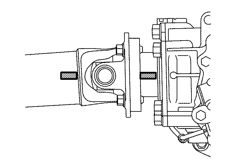
Propeller Shaft Runout
Check propeller shaft runout at measuring points with a dial indicator. If runout exceeds specifications, replace propeller shaft assembly.
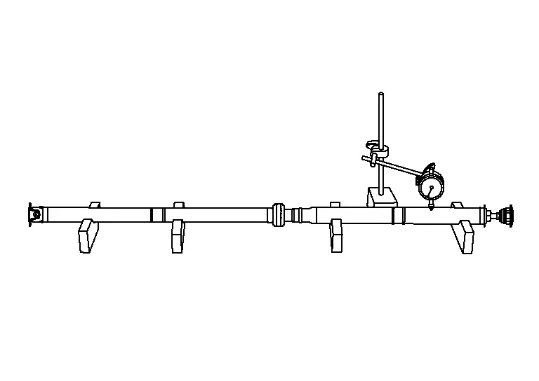
| Propeller shaft runout | : Refer to Propeller Shaft Runout. |
| A. | Runout measure range |
 |
: Front |
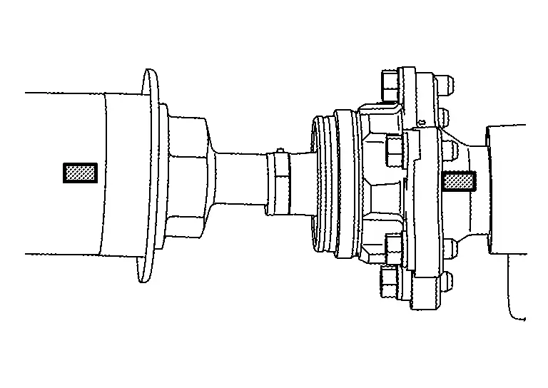
Journal Axial Play
As shown, while fixing yoke on one side, check axial play of joint. If it is outside the standard, replace propeller shaft assembly.
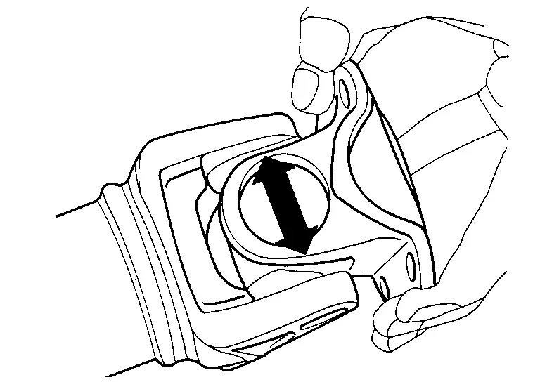
| Journal axial play | : Refer to Journal Axial Play. |
CAUTION:
Do not disassemble joints.
Center Bearing
Check center bearing for noise and damage. If noise or damage is detected, replace propeller shaft assembly.
CAUTION:
Do not disassemble center bearing.
Inspection After Installation
After assembly, perform a driving test to check propeller shaft vibration. If vibration occurs refer to Inspection.
Service Data and Specifications (SDS) Nissan Pathfinder
General Specifications
| Applied model | 4WD | ||||||
|---|---|---|---|---|---|---|---|
| VQ35DD | |||||||
| 9AT | |||||||
| Propeller shaft model | 3FCJ-CVJ | ||||||
| Number of joints | 3 | ||||||
|
Type of journal bearings (Non-disassembly type) |
1st joint | Shell type | |||||
| 2nd joint | CVJ type | ||||||
| 3rd joint | Shell type | ||||||
| Coupling method with transfer | Flange type | ||||||
| Coupling method with rear final drive | Flange type | ||||||
| Shaft length | 1st (Spider to EDJ joint center) | 1,327 mm (52.24 in) | |||||
| 2nd (EDJ joint center to spider) | 1000 mm (39.37 in) | ||||||
| Shaft outer diameter | 1st | 70 mm (2.76 in) | |||||
| 2nd | 80 mm 3.15 in) | ||||||
Propeller Shaft Runout
Unit: mm (in)
| Item | Limit | ||
|---|---|---|---|
| Propeller shaft runout | 0.8 (0.031) |
Journal Axial Play
Unit: mm (in)
| Item | Standard | ||
|---|---|---|---|
| Journal axial play | 0 (0) |

Nissan Pathfinder (R53) 2022-2026 Service Manual
Rear Propeller Shaft: 3fcj-Cvj
- Precautions
- Preparation
- Symptom Diagnosis. Noise, Vibration and Harshness (nvh) Troubleshooting
- Basic Inspection. Propeller Shaft Assembly
- Removal and Installation. Rear Propeller Shaft
- Service Data and Specifications (SDS)
Contact Us
Nissan Pathfinder Info Center
Email: info@nipathfinder.com
Phone: +1 (800) 123-4567
Address: 123 Pathfinder Blvd, Nashville, TN 37214, USA
Working Hours: Mon–Fri, 9:00 AM – 5:00 PM (EST)
