Nissan Pathfinder: Heater & Air Conditioning System - Periodic Maintenance
Refrigerant Nissan Pathfinder
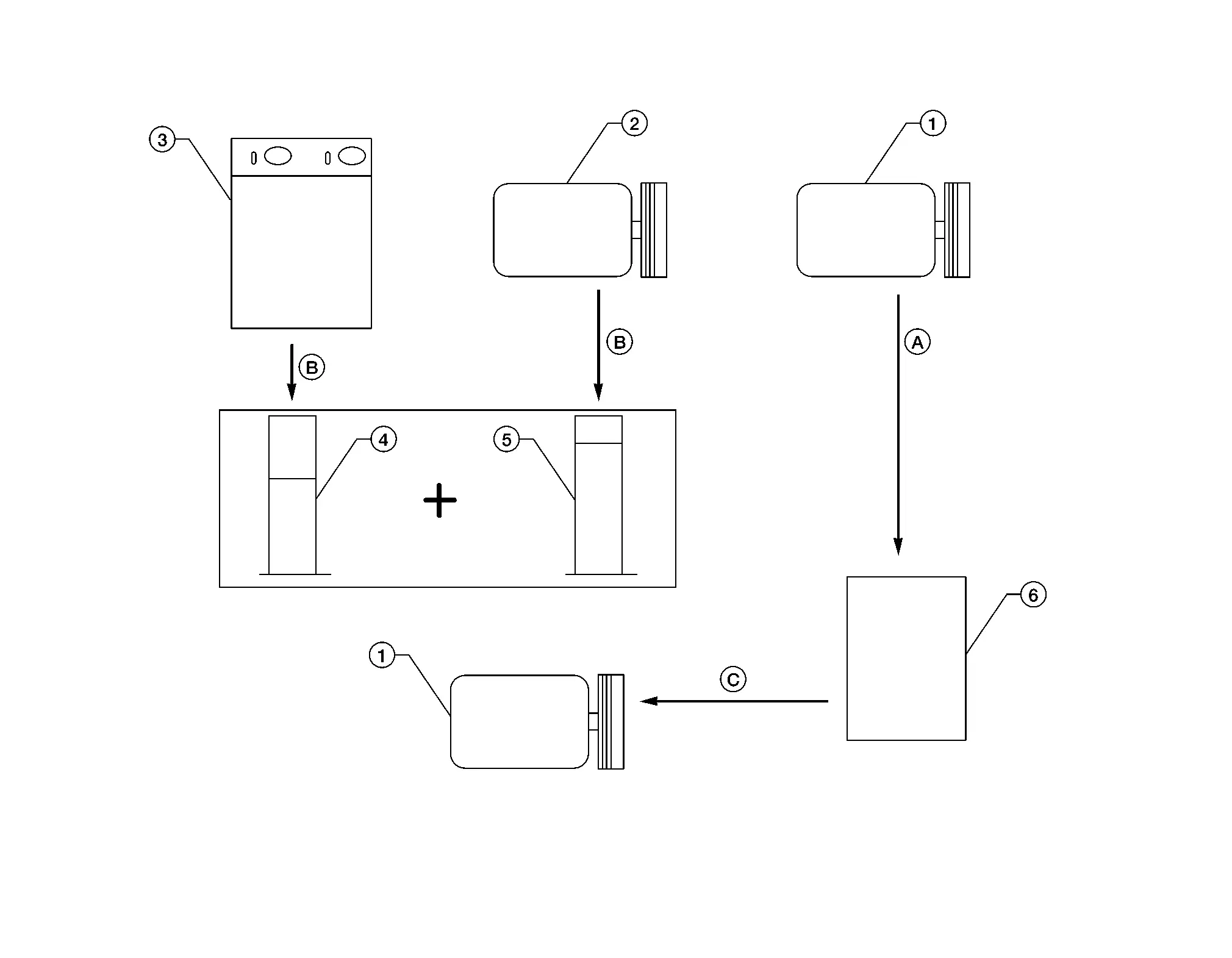
Description
CONNECTION OF SERVICE TOOLS AND EQUIPMENT
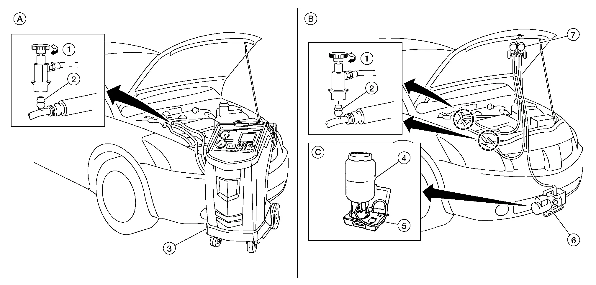
| 1. | Shut-off valve | 2. | A/C service valve | 3. | Recovery/recycling/recharging equipment |
| 4. | Refrigerant container (HFO-1234yf) | 5. | Weight scale | 6. | Vacuum pump |
| 7. | Manifold gauge set | ||||
| A. | Preferred (best) method | B. | Alternative method | C. | For charging |
Leak Test
CHECK REFRIGERANT LEAKS USING FLUORESCENT LEAK DETECTION DYE
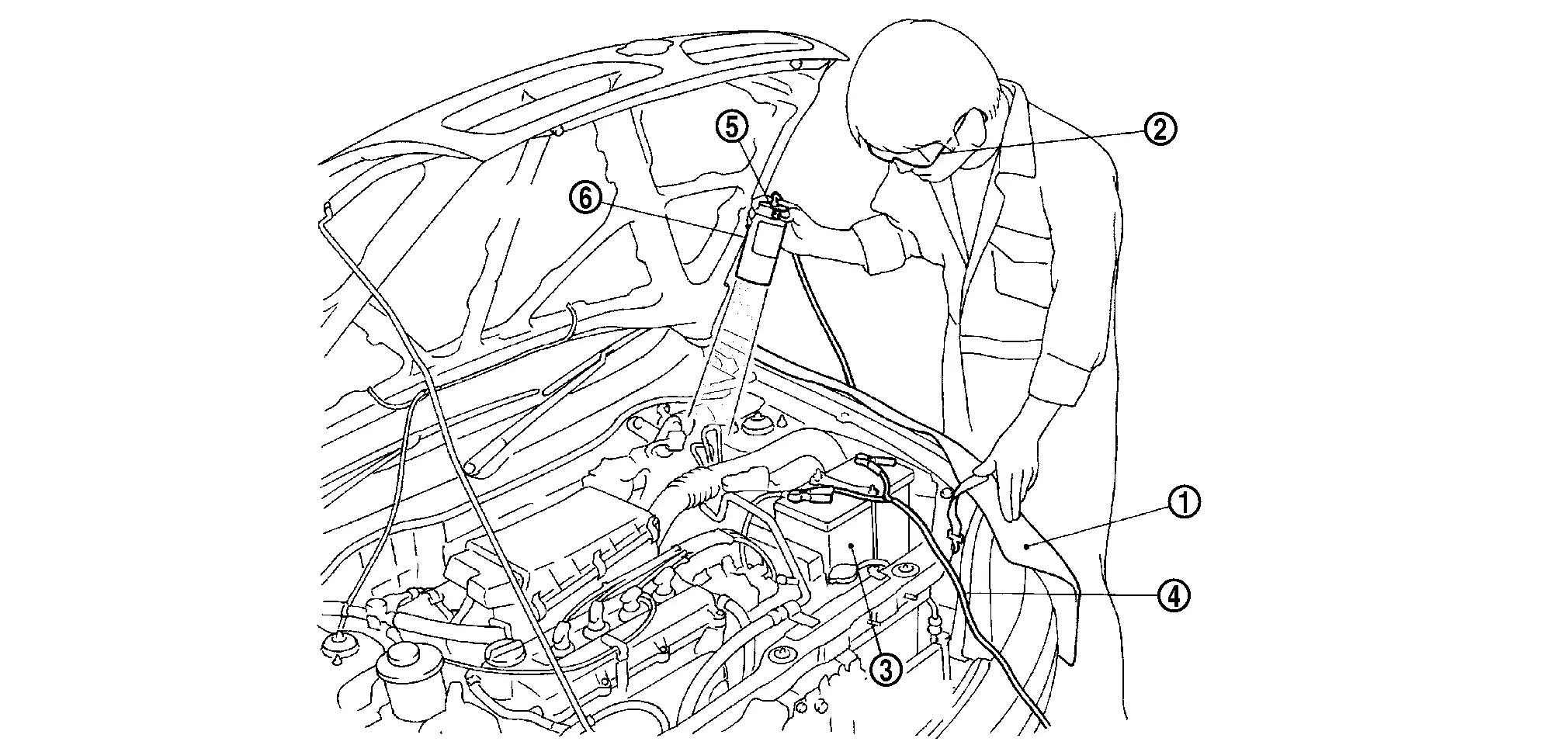
Install a fender cover (1).
Wear UV safety goggles (2) provided with refrigerant dye leak detection kit.
Connect power cable (4) of UV lamp (6) to positive and negative terminals of the battery (3).
Press UV lamp switch (5) and check A/C system for refrigerant leaks. (Where refrigerant leaks occur, fluorescent leak detection dye appears in green color.)
WARNING:
Do not look directly into UV lamp light source.
 NOTE:
NOTE:
-
For continuous operating time of UV lamp, follow the manufacturer’s operating instructions.
-
Illuminate piping joints from different angles using UV lamp and check that there are no leaks.
-
Use a mirror in areas that are difficult to see to check for refrigerant leaks.
-
Refrigerant leaks from evaporator can be detected by soaking a cotton swab or a similar materials with drain hose water and illuminating it using UV lamp.
-
Dust, dirt, and packing materials adhesive used for condenser, evaporator, and other locations may fluoresce. Be careful not to misidentify leaks.
Repair or replace parts where refrigerant leaks occur and wipe off fluorescent leak detection dye.
 NOTE:
NOTE:
Completely wipe off fluorescent leak detection dye from gaps between parts, screw threads, and others using a cotton swab or similar materials.
Use a UV lamp to check that no fluorescent leak detection dye remains after finishing work.
WARNING:
Do not look directly into UV lamp light source.
 NOTE:
NOTE:
-
For continuous operating time of UV lamp, follow the manufacturer’s operating instructions.
-
Dust, dirt, and packing materials adhesive used for condenser, evaporator, and other locations may fluoresce. Be careful not to misidentify leaks.
CHECK REFRIGERANT LEAKS USING ELECTRONIC LEAK DETECTOR
WARNING:
Do not check for refrigerant leaks while the engine is running.
CAUTION:
Be careful of the following items so that inaccurate checks or misidentifications are avoided.
-
Do not allow refrigerant vapor, shop chemical vapors, cigarette smoke or others around the Nissan Pathfinder vehicle.
-
Always check for refrigerant leaks in a low air flow environment so that refrigerant may not disperse when leaks occur.
Stop the engine.
Connect recovery/recycling/recharging equipment or manifold gauge set to A/C service valve.
Check that A/C refrigerant pressure is 345 kPa (3.52 kg/cm2, 50 psi) or more when temperature is 16°C (61°F) or more. When pressure is lower than the specified value, recycle refrigerant completely and fill refrigerant to the specified level.
 NOTE:
NOTE:
Leaks may not be detected if A/C refrigerant pressure is 345 kPa (3.52 kg/cm2, 50 psi) or less when temperature is less than 16°C (61°F).
Clean area where refrigerant leak check is performed and check for refrigerant leaks along all surfaces of pipe connections and A/C system components using electronic leak detector probe.
CAUTION:
-
Continue checking when a leak is found. Always continue and complete checking along all pipe connections and A/C system components for additional leaks.
-
When a leak is detected, clean leak area using compressed air and check again.
-
When checking for leaks inside the cooling unit, always clean inside the drain hose so that the probe surface may not be exposed to water or dirt.
 NOTE:
NOTE:
-
Always check for leaks starting from high-pressure side and continuing to low-pressure side.
-
When checking for leaks inside the cooling unit, operate blower fan motor for 15 minutes or more at the maximum fan speed while the engine is stopped, and then insert electrical leak detector probe into drain hose and hold for 10 minutes or more.
-
When disconnecting shut-off valve that is connected to A/C service valve, always evacuate remaining refrigerant so that misidentification can be avoided.
Repair or replace parts where refrigerant leaks are detected.
Start the engine and set A/C control in the following conditions:
-
A/C switch ON
-
Air flow: VENT (ventilation)
-
Intake door position: Recirculation
-
Temperature setting: Full cold
-
Fan (blower) speed: Maximum speed set
Run the engine at approximately 1,500 rpm for 2 minutes or more.
Stop the engine. Check again for refrigerant leakage. Go to step 4.
WARNING:
Be careful not to get burned when the engine is hot.
 NOTE:
NOTE:
-
Start refrigerant leak check immediately after the engine is stopped.
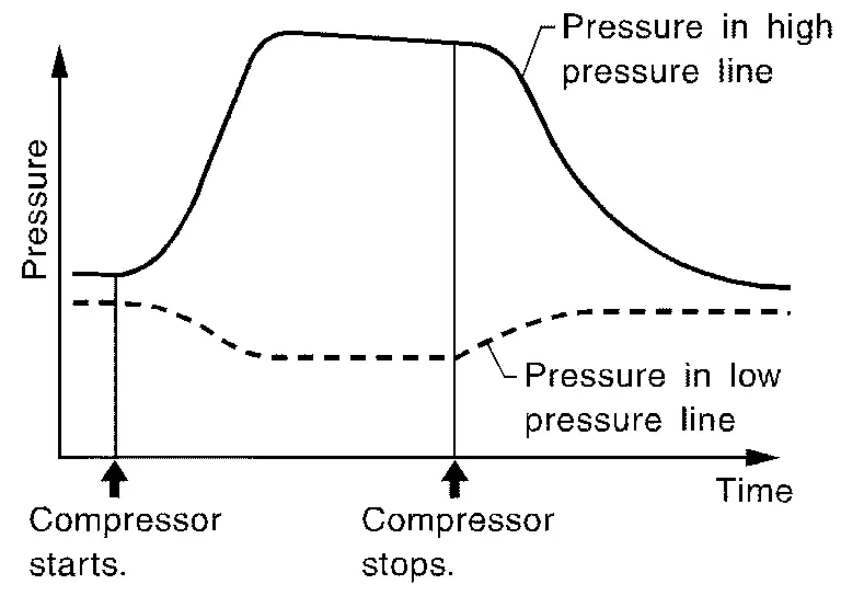
-
When refrigerant circulation is stopped, pressure on the low-pressure side rises gradually, and after this, pressure on the high-pressure side falls gradually.
-
The higher the pressure is, the easier it is to find the refrigerant leaks.
Recycle Refrigerant
WARNING:
-
Always use HFO-1234yf for A/C refrigerant. If HFC-134a is accidentally charged, compressor is damaged due to insufficient lubrication.
-
Always observe and follow precautions described on refrigerant container. Incorrect handling may result in an explosion of refrigerant container, frostbite or the loss of eyesight.
-
Do not breathe A/C refrigerant and oil vapor or mist. Exposure may irritate eyes, nose, or throat.
-
Do not allow HFO-1234yf to be exposed to an open flame or others because it generates poisonous gas when in contact with high temperature objects. Keep workshop well ventilated.
Perform oil return operation. Refer to Perform Oil Return Operation. (If refrigerant or oil leak is detected in a large amount, omit this step, and go to step 2.)
CAUTION:
Do not perform oil return operation if a large amount of refrigerant or oil leak is detected.
Check gauge pressure readings of recovery/recycling/recharging equipment. When remaining pressure exists, recycle refrigerant from high-pressure hose and low-pressure hose.
 NOTE:
NOTE:
Follow manufacturer instructions for the handling or maintenance of the equipment. Do not fill the equipment with non-specified refrigerant.
Remove A/C service valve cap from the Nissan Pathfinder vehicle.
Connect recovery/recycling/recharging equipment to A/C service valve.
Operate recovery/recycling/recharging equipment, and recycle refrigerant from the Nissan Pathfinder vehicle.
Evacuate air for 10 minutes or more to remove any remaining refrigerant integrated to compressor oil, etc.
Refrigerant recycle operation is complete.
Charge Refrigerant
WARNING:
-
Always use HFO-1234yf for A/C refrigerant. If HFC-134a is accidentally charged, compressor is damaged due to insufficient lubrication.
-
Always observe and follow precautions described on refrigerant container. Incorrect handling may result in an explosion of refrigerant container, frostbite, or the loss of eyesight.
-
Do not breathe A/C refrigerant and oil vapor or mist. Exposure my irritate eyes, nose, or throat.
-
Do not allow HFO-1234yf to be exposed to an open flame or others because it generates poisonous gas when in contact with high temperature objects. Keep workshop well ventilated.
Connect recovery/recycling/recharging equipment to the A/C service valve.
Operate recovery/recycling/recharging equipment, and evacuate air from A/C system for 25 minutes or more.
CAUTION:
Evacuate air for 15 minutes or more if the parts are replaced.
Check the airtightness of A/C system for 25 minutes or more. If pressure raises more than the specified level, charge A/C system with approximately 200g refrigerant and check that there is no refrigerant leak. Refer to Leak Test.
CAUTION:
Check the airtightness for 15 minutes or more if the parts are replaced.
If parts other than compressor are replaced, fill compressor oil according to parts that are replaced.
Charge the specified amount of refrigerant to A/C system.
Check that A/C system operates normally.
Disconnect recovery/recycling/recharging equipment. (Collect the refrigerant from the high-pressure hose and low-pressure hose of recovery/recycling/recharging equipment.)
Install A/C service valve cap.
Refrigerant charge is complete.
Oil Nissan Pathfinder 2022
Description
MAINTENANCE OF OIL LEVEL
The compressor oil is circulating in the system together with the refrigerant. It is necessary to fill compressor with oil when replacing A/C system parts or when a large amount of refrigerant leakage is detected. It is important to always maintain oil level within the specified level or otherwise the following conditions may occur:
-
Insufficient oil amount: Stuck compressor
-
Excessive oil amount: Insufficient cooling (caused by insufficient heat exchange)
| Oil Type | : Oil. |
Inspection
If a compressor is malfunctioning (internal noise, insufficient cooling), check the compressor oil.
COMPRESSOR OIL JUDGMENT
-
Remove the compressor. Refer to Removal and Installation.
-
Sample compressor oil and judge below according to the figure.
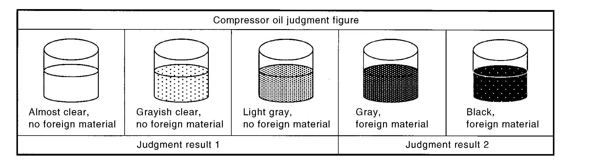
Judgement result 1>>
Replace compressor only.
Judgement result 2>>Replace compressor and condenser (includes liquid tank).
Perform Oil Return Operation
CAUTION:
If a large amount of refrigerant or oil leakage is detected, do not perform oil return operation.
Start the engine and set to the following conditions:
-
Engine speed: Idling to 1,200 rpm
-
A/C switch: ON
-
Fan (blower) speed: Maximum speed set
-
Intake door position: Recirculation
-
Temperature setting: Full cold
Perform oil return operation for approximately 10 minutes.
Stop the engine.
Oil return operation is complete.
Oil Adjusting Procedure for Components Replacement Except Compressor
Fill with oil for the amount that is calculated according to the following conditions.
Example: Oil amount to be added when replacing evaporator [m
 (US fl oz, Imp fl oz)] = 75 (2.5, 2.6) + α
| Conditions |
Oil amount to be added to A/C system m (US fl oz, Imp fl oz) (US fl oz, Imp fl oz) | |
|---|---|---|
| Replace evaporator | 75 (2.5, 2.6) | |
| Replace condenser (includes liquid tank) | 80 (2.7, 2.8) | |
| Refrigerant leakage is detected | Large amount leakage | 30 (1.0, 1.1) |
| Small amount leakage | — | |
| Oil amount that is recycled together with refrigerant during recycle operation | α | |
Oil Adjusting Procedure for Compressor Replacement
| 1. | New compressor | 2. | Old compressor | 3. | Recovery/recycling equipment |
| 4. | Measuring cup X | 5. | Measuring cup Y | 6. | New oil |
| A. | Drain oil from the new compressor into clean container | B. | Record amount of oil recovered | C. | Install new oil equal to recorded amounts in measuring cups X and Y |
Before connecting recovery/recycling equipment to vehicle, check recovery/recycling equipment gauges. No refrigerant pressure should be displayed. If NG, recover refrigerant from equipment lines.
Connect recovery/recycling equipment to Nissan Pathfinder vehicle. Confirm refrigerant purity in supply tank using recovery/recycling equipment and refrigerant identifier. If NG, refer to Precautions For Refrigerant System Service.
Confirm refrigerant purity in Nissan Pathfinder vehicle A/C system using recovery/recycling equipment and refrigerant identifier. If NG, refer to Precautions For Refrigerant System Service.
Discharge refrigerant into the refrigerant recovery/recycling equipment. Measure oil discharged into the recovery/recycling equipment.
Drain the oil from the “old” (removed) compressor into a graduated container and recover the amount of oil drained.
Drain the oil from the “new” compressor into a separate, clean container.
Measure an amount of new oil installed equal to amount drained from “old” compressor. Add this oil to “new” compressor through the suction port opening.
Measure an amount of new oil equal to the amount recovered during discharging. Add this oil to “new” compressor through the suction port opening.
Performance Test Nissan Pathfinder Fifth generation
Inspection
INSPECTION PROCEDURE
-
Connect recovery/recycling/recharging equipment (for HFO-1234yf) or manifold gauge.
-
Start the engine, and set to the following condition.
Test condition Surrounding condition Indoors or in the shade (in a well-ventilated place) Nissan Pathfinder Vehicle condition Door Closed Door glass Full open Hood Open Engine speed Idle speed A/C condition Temperature control switch or dial Full cold A/C switch ON Air outlet VENT (ventilation) Intake door position Recirculation Fan (blower) speed Maximum speed set -
Maintain test condition until A/C system becomes stable. (Approximately 10 minutes)
-
Check that test results of “recirculating-to-discharge air temperature” and “ambient air temperature-to-operating pressure” are within the specified value.
-
When test results are within the specified value, inspection is complete.
If any of test result is out of the specified value, perform diagnosis by gauge pressure. Refer to Symptom Table.
RECIRCULATING-TO-DISCHARGE AIR TEMPERATURE TABLE
| Inside air (Recirculating air) at blower assembly inlet |
Vent outlet temperature °C (°F) |
Vent outlet temperature °C (°F) |
Vent outlet temperature °C (°F) | |
|---|---|---|---|---|
|
Relative humidity % |
Air temperature °C (°F) | 1st Row | 2nd Row | 3rd Row |
| 50 – 60 | 25 (77) | 7.0 – 7.8 (45 – 46) | 9.2 – 10.2 (49 – 50 | 8.5 – 9.4 (47 – 49) |
| 30 (86) | 11.5 – 12.8 (53 – 55) | 13.7 – 15.2 (57–59) | 13.0 – 14.4 (55 – 58) | |
| 35 (95) | 13.9 – 15.4 (57 – 60) | 16.6 – 18.4 (62 – 65) | 15.7 – 17.4 (60 – 63) | |
| 40 (104) | 14.9 – 16.5 (59 – 62) | 19.4 – 21.6 (67–71) | 17.7 – 19.7 (64 – 67) | |
| 60 – 70 | 25 (77) | 7.8 – 8.6 (46 – 47) | 10.2 – 11.2 (50 – 52) | 9.4 – 10.3 (49 – 51) |
| 30 (86) | 12.8 – 14.1 (55 – 57) | 15.2 – 16.7 (59 – 62) | 14.4 – 15.8 (58 – 61) | |
| 35 (95) | 15.4 – 16.9 (60 – 62) | 18.4 – 20.2 (65 – 68) | 17.4 – 19.1 (63 – 66) | |
| 40 (104) | 16.5 – 18.2 (62 – 65) | 21.6 – 23.8 (71 – 75) | 19.7 – 21.7 (67 – 71) | |
AMBIENT AIR TEMPERATURE-TO-OPERATING PRESSURE TABLE
| Fresh air |
High-pressure (Discharge side) kPa (kg/cm2, psi) |
Low-pressure (Suction side) kPa (kg/cm2, psi) | |
|---|---|---|---|
|
Relative humidity % |
Air temperature °C (°F) | ||
| 50 – 70 | 25 (77) |
900 – 1,100 (9.2 – 11.2, 131 – 160) |
215 – 263 (2.20 – 2.68, 31 – 38) |
| 30 (86) |
1,253 – 1,532 (12.8 – 15.6, 182 – 222) |
273 – 333 (2.78 – 3.40, 40 – 48) |
|
| 35 (95) |
1,509 – 1,845 (15.4 – 18.8, 219 – 268) |
300 – 367 (3.06 – 3.74, 44 – 53) |
|
| 40 (104) |
1,536 – 1,877 (15.7 – 19.1, 223 – 272) |
315 – 385 (3.21 – 3.93, 46 – 56 |
|

Nissan Pathfinder (R53) 2022-2026 Service Manual
Periodic Maintenance
Contact Us
Nissan Pathfinder Info Center
Email: info@nipathfinder.com
Phone: +1 (800) 123-4567
Address: 123 Pathfinder Blvd, Nashville, TN 37214, USA
Working Hours: Mon–Fri, 9:00 AM – 5:00 PM (EST)
