Nissan Pathfinder: Audio, Visual & Navigation System - System Description
Component Parts ➤ Nissan Pathfinder
System ➤ Nissan Pathfinder 2022
Diagnosis System (av Control Unit) Nissan Pathfinder 2022
Description
The AV control unit on board diagnosis performs the following functions listed in the table below:
| Mode | Description | |
|---|---|---|
| Self Diagnosis |
|
|
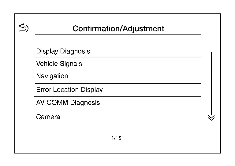
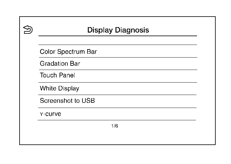
| Confirmation/Adjustment | Display Diagnosis |
The following check functions are available:
|
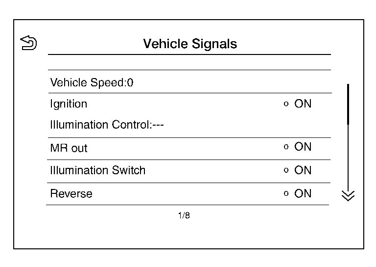
| Nissan Pathfinder Vehicle Signals | Diagnosis of signals can be performed for Vehicle Speed, Ignition, Illumination Control, MR out, Illumination Switch, Reverse, Parking Brake and ACC. | |
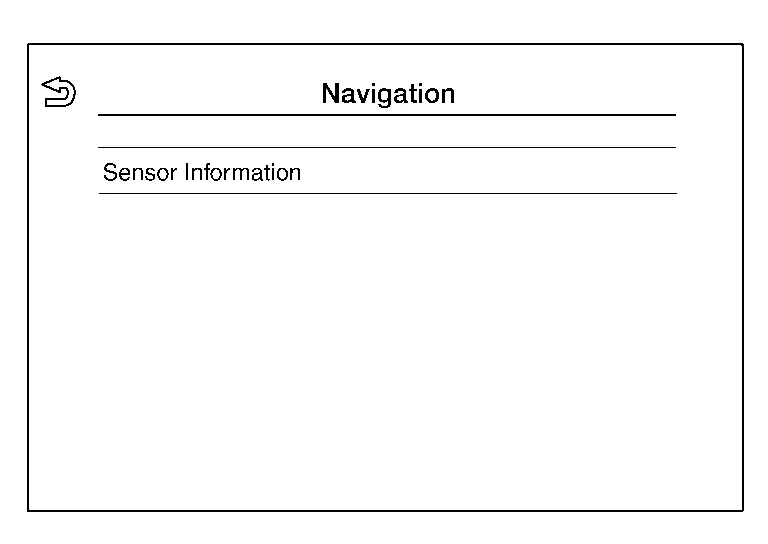
| Navigation | Sensor information can be checked. | |
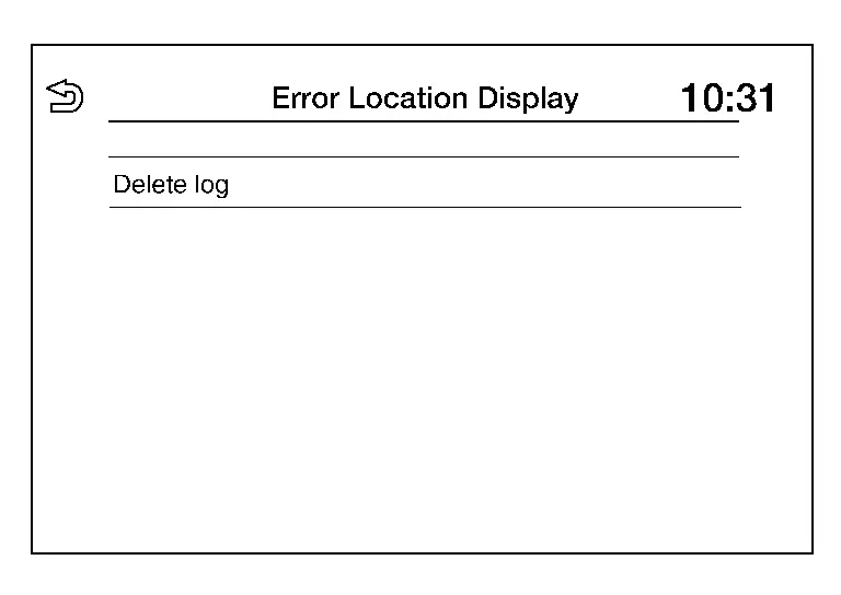
| Error Location Display | The system malfunction and the frequency when occurring in the past are displayed. When the malfunctioning item is selected, the time that the selected malfunction last occurred is displayed. | |
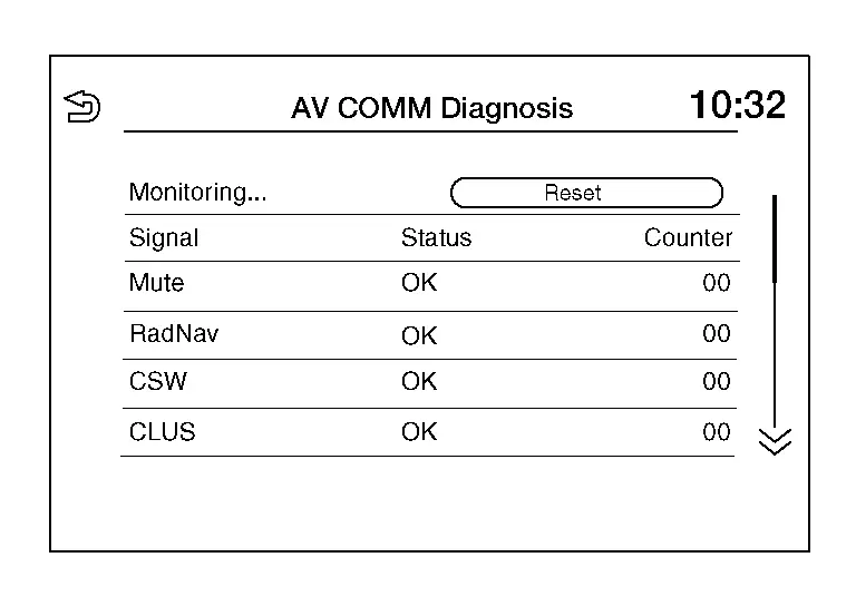
| AV COMM Diagnosis | The AV communication condition of each unit of audio system can be monitored. | |
| Camera |
The following functions are available:
|
|
| Delete Unit Connection Log | Erase the connection history of unit. | |
| Initialize Settings | User Data Initialization is available. | |
| GPS Time Set | The date and time information can be adjusted. | |
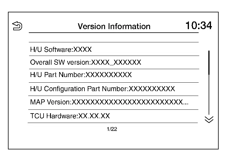
| Version Information | Version information of the Multi AV system is displayed. | |
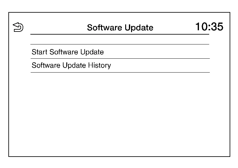
| Software Update |
|
|
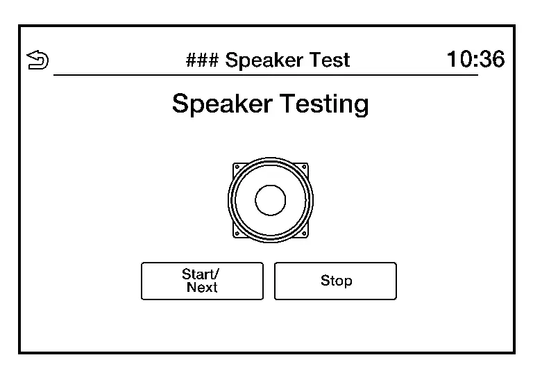
| ### Speaker Test | Individual speakers can be checked at the 100Hz and 4KHz range. | |
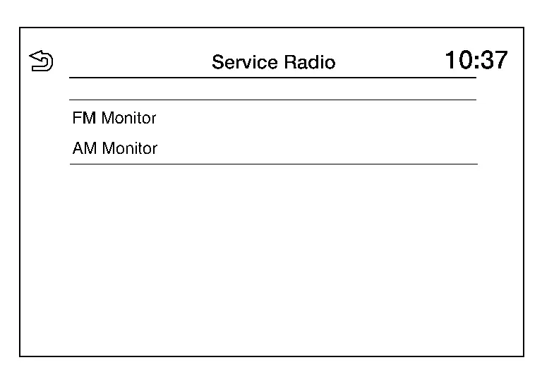
| Radio Tuner | FM Monitor and AM Monitor information can be observed. | |
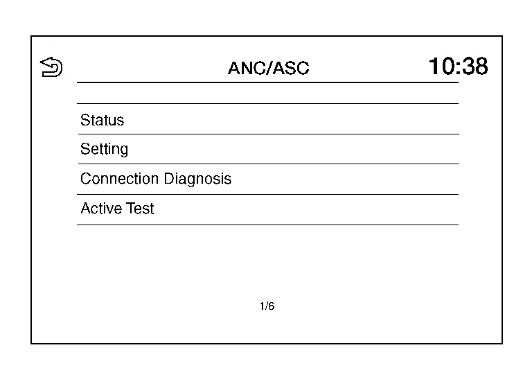
| ANC/ASC | Displayed, but not used. | |
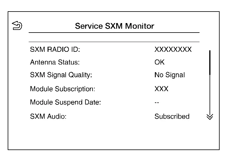
| SXM | SXM Monitor information can be observed. | |
Perform CONSULT diagnosis if the AV control unit on board diagnosis does not start, or the screen does not display anything.
On Board Diagnosis Function
METHOD OF STARTING
AV Control Unit Self Diagnosis
-
Ignition switch ON.
-
Audio system OFF.
-
While MENU button is pressed, rotate the TUNE-SCROLL dial counterclockwise for 3 or more clicks, clockwise for 3 or more clicks, counterclockwise for 3 or more clicks. Shifting from current screen to previous screen is performed by pressing BACK button.
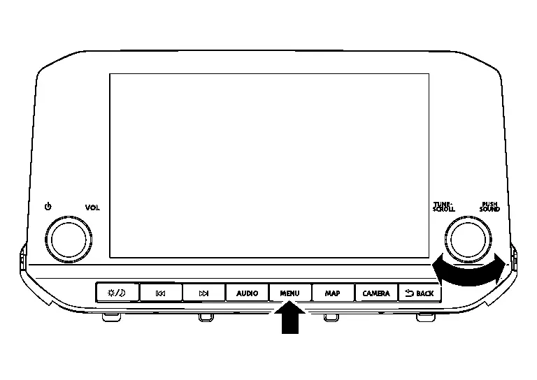
-
The trouble diagnosis initial screen is displayed, and “Self-Diagnosis” and “Confirmation/Adjustment” can be selected.
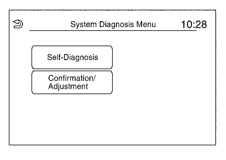
SELF-DIAGNOSIS MODE
-
Start the self-diagnosis function and select “Self Diagnosis”.
-
Self-diagnosis subdivision screen is displayed, and the self-diagnosis mode starts.
-
The bar graph visible on the center of the self-diagnosis subdivision screen indicates progress of the trouble diagnosis.
-
-
Diagnosis results are displayed after the self-diagnosis is completed. The unit names and the connection lines are color-coded according to the diagnostic results.
Diagnosis results Unit Connection line Normal Green Green Connection malfunction Gray Yellow Unit malfunction Note Red Green  NOTE:
NOTE:
AV control Unit (Head Unit) is displayed in red.
-
Replace AV control unit if “Self-Diagnosis did not run because of a control unit malfunction” is indicated. The symptom is AV control unit internal error. Refer to Removal and Installation.
-
If multiple errors occur at the same time for a single unit, the screen switch colors are determined according to the following order of priority: red > gray.
-
-
MCAN, Head Unit and VCAN are displayed:
-
Press the MCAN button and the system components connected via AV communication are displayed.
-
Press the Head Unit button and the components connected to the AV control unit are displayed.
-
Press the VCAN button and the system components connected via CAN communication are displayed. Refer to Trouble Diagnosis Flow Chart for CAN communication diagnosis.
-
Detection Range of Self-diagnosis Mode
-
The self-diagnosis mode allows the technician to diagnose the connection in the communication line between AV control unit and each unit and the internal operation of the AV control unit.
-
Because the start condition of diagnosis function is a switch operation, the on board diagnosis function cannot be started up if any malfunction is detected in the AV control unit switches.
SELF-DIAGNOSIS RESULTS
Only Unit Part Is Displayed In Red (MCAN)
| Screen switch | Description | Possible malfunction location / Action to take |
|---|---|---|
| Head Unit | Malfunction is detected in AV control unit power supply and ground circuits. |
Check AV control unit power supply and ground circuits. Refer to Diagnosis Procedure. When no malfunction is detected in those circuits, replace AV control unit. Refer to Removal and Installation. |
| DiagMuxMCAN | Displayed, but not used. | |
| Meter | Malfunction is detected in combination meter power supply and ground circuits. |
Check combination meter power supply and ground circuits. Refer to Diagnosis Procedure (Full TFT Meter) or Diagnosis Procedure (7 Inch Information Display). When no malfunction is detected in those circuits, replace combination meter. Refer to Removal and Installation (Full TFT Meter) or Removal and Installation (7 Inch Information Display). |
Only Unit Part Is Displayed In Red (Head Unit)
| Screen switch | Description | Possible malfunction location / Action to take |
|---|---|---|
| Head Unit | Malfunction is detected in AV control unit power supply and ground circuits. |
Check AV control unit power supply and ground circuits. Refer to Diagnosis Procedure. When no malfunction is detected in those circuits, replace AV control unit. Refer to Removal and Installation. |
| Amplifier | Malfunction is detected in the internal amplifier of the AV control unit. |
Replace the AV control unit. Refer to Removal and Installation. |
| Conn Modules | Malfunction is detected in the internal Bluetooth® module of the AV control unit. |
Replace the AV control unit. Refer to Removal and Installation. |
| Antenna | Malfunction is detected in antenna signal circuit. |
Check antenna signal circuit. Refer to Diagnosis Procedure. When no malfunction is detected in the circuit, replace antenna. Refer to Removal and Installation. |
| LVDS | Malfunction is detected in the LVDS harness for the around view monitor control unit. | Replace the LVDS harness. |
| USB |
|
Replace the USB harness. |
| FAN | Malfunction is detected in the internal fan of the AV control unit. |
Replace the AV control unit. Refer to Removal and Installation. |
A Connecting Cable Between Units Is Displayed In Yellow (MCAN)
| Area with yellow connection lines | Description | Possible malfunction location / Action to take |
|---|---|---|
| Head Unit ⇔ DiagMuxMCAN | Displayed, but not used. | |
| Head unit ⇔ Meter | Combination meter AV communication connection malfunction detected. |
AV communication circuits between AV control unit and combination meter. Refer to Diagnosis Procedure. |
A Connecting Cable Between Units Is Displayed In Yellow (Head Unit)
| Area with yellow connection lines | Description | Possible malfunction location / Action to take |
|---|---|---|
| Head Unit ⇔ Amplifier | Internal amplifier malfunction detected. |
Replace the AV control unit. Refer to Removal and Installation. |
| Head Unit ⇔ Conn Modules | Internal Bluetooth® module malfunction detected. |
Replace the AV control unit. Refer to Removal and Installation. |
| Head Unit ⇔ Antenna | Antenna connection malfunction detected. |
Antenna disconnected. Refer to Diagnosis Procedure. |
| Head Unit ⇔ LVDS | LVDS harness for around view monitor control unit connection malfunction detected. | LVDS harness disconnected. |
| Head unit ⇔ USB |
|
USB harness disconnected. |
| Head Unit ⇔ FAN | Internal fan malfunction detected. |
Replace the AV control unit. Refer to Removal and Installation. |
CONFIRMATION/ADJUSTMENT MODE
-
Start the diagnosis function and select “Confirmation/Adjustment”. The confirmation/adjustment mode indicates where each item can be checked or adjusted.
-
Select each switch on the “Confirmation/Adjustment Mode” screen to display the relevant trouble diagnosis screen. Touch the “Back” to return to the initial Confirmation/Adjustment Mode screen.
Display Diagnosis
Confirmation of the AV control unit screen operation.
Vehicle Signals
A comparison check can be made of each actual vehicle signal and the signals recognized by the system.
Navigation
The reception status of GPS can be confirmed.
Error Location Display
Results of the error occurrence are represented by the time the error occurred.
AV COMM Diagnosis
AV COMM Monitor
-
Displays the communication status between AV control unit (master unit) and each unit.
-
The error counter displays “OK” if any malfunction was not detected in the past and displays “0” if a malfunction is detected. It increases by 1 if the condition is normal at the next ignition switch ON cycle. The upper limit of the counter is 39.
-
The error counter is erased if “Reset” is pressed.
Camera
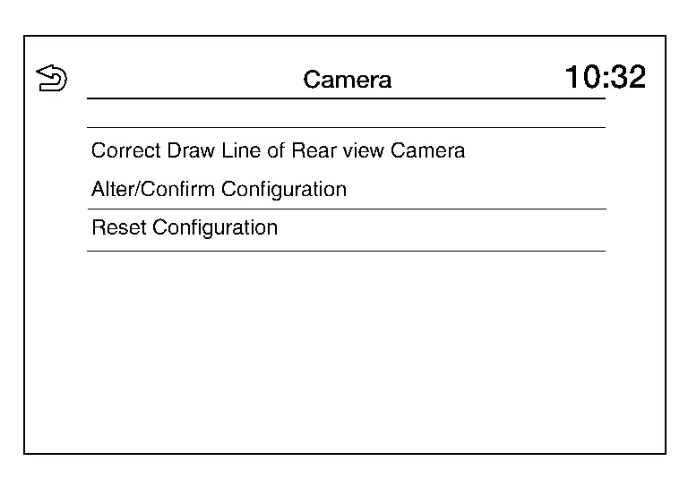
| Item | Description |
|---|---|
| Correct Draw Line of Rear view Camera | The guiding lines in the rear view monitor can be adjusted. |
| Alter/Confirm Configuration | Displays the current configuration data. |
| Reset Configuration | Initializes the camera system configuration. |
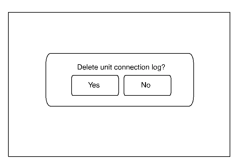
Delete Unit Connection Log
Deletes error records from the AV control unit memory.
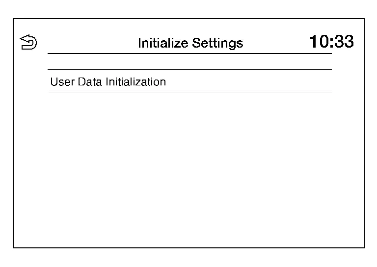
Initialize Settings
Initializes the AV control unit memory.
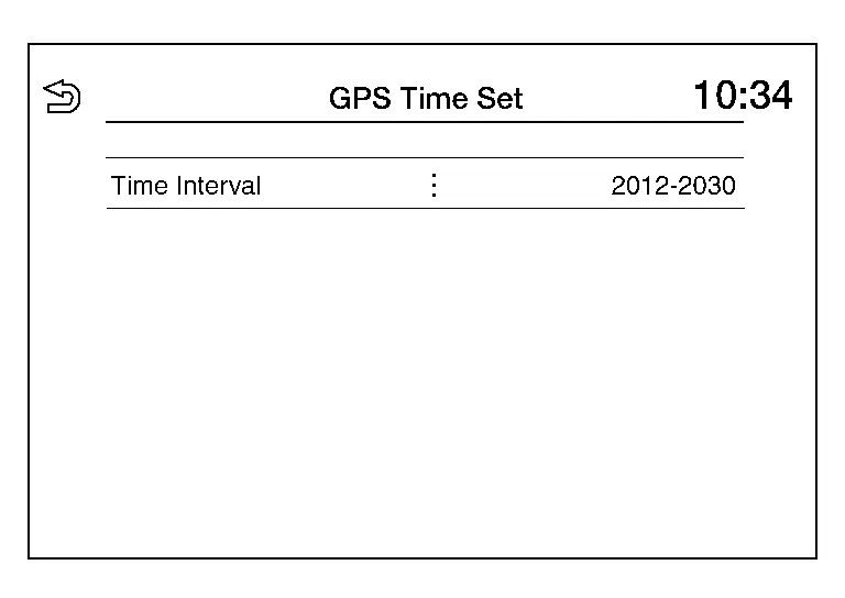
GPS Time Set
Date and time information can be adjusted.
Version Information
Version information of the components of the Multi AV system are displayed.
Software Update
Version of the AV control unit software can be updated.
### Speaker Test
Two test tones, 100Hz and 4KHz, can be generated to each speaker.
Radio Tuner
Displays FM and AM monitor information.
ANC/ASC
Displayed, but not used.
SXM
Displays SXM monitor information.
CONSULT Function
APPLICATION ITEMS
CONSULT performs the following functions via communication with the AV control unit:
| Diagnosis mode | Description |
|---|---|
| Self Diagnostic Result | The AV control unit self diagnostic results are displayed. |
| Data Monitor | The AV control unit input/output data is displayed in real time. |
| Work Support |
|
| ECU Identification | The AV control unit part number is displayed. |
| Configuration* | Writes the Nissan Pathfinder vehicle specification when replacing AV control unit. |
*: Displays when performing "Diagnosis (All System)".
SELF DIAGNOSIS RESULT
-
In CONSULT self-diagnosis, self-diagnosis results and error history are displayed collectively.
-
The current malfunction indicates “CRNT”. The past malfunction indicates “PAST”.
-
Refer to DTC Index.
Freeze Frame Data (FFD)
The following vehicle status is recorded when DTC is detected and is displayed on CONSULT.
| Item name | Display content |
|---|---|
|
ODO/TRIP METER [km] |
Total driving distance (odometer value) upon DTC detection is displayed. |
|
DTC count [count] |
The number of times the DTC is detected is displayed. |
DATA MONITOR
 NOTE:
NOTE:
The following table includes information (items) inapplicable to this Nissan Pathfinder vehicle. For information (items) applicable to this vehicle, refer to CONSULT display items.
-
Displays the status of the following vehicle signals inputted into the AV control unit.
-
For each signal, actual signal can be compared with the condition recognized on the system.
| Monitor Item [Unit] | Description |
|---|---|
| Sunload sensor [On/Off] | Indicates sunload sensor signal received from A/C auto amp. on CAN communication line. |
| Parking brake [On/Off] | Indicates condition of parking brake signal for the AV control unit. |
| IGN SIG [On/Off] | Indicates condition of ignition signal. |
| Auto ACC [On/Off] |
It depends on Nissan Pathfinder vehicle architecture. |
| ACC [On/Off] | Indicates condition of ACC signal. |
| Aux IN 1* [Con/No con] | Indicates connection condition of USB. |
| TCU mute signal [On/Off] | Indicates condition of mute signal received from TCU. |
| REV SIG [On/Off] | Indicates condition of reverse signal for the AV control unit. |
| ILLUM SIG [On/Off] | Indicates condition of illumination signal for the AV control unit. |
| Illumination Control [On/Off] | Indicates condition of illumination control signal for the AV control unit. |
 NOTE:
NOTE:
*: If so equipped
WORK SUPPORT
| Item | Remarks |
|---|---|
| SAVE VIN DATA | Allows the reading of VIN written in AV control unit to store the specification in CONSULT. |
| WRITE VIN (SAVED DATA) | Allows the writing of the VIN stored in CONSULT into the AV control unit. |
| VIN REGISTRATION | Allows the writing of the VIN to the AV control unit. |
| Network initial settings | Perform AV control unit communication initialization. |
If network initial settings are not completed, refer to the following for details of displayed numbers.
| Item | Value | Description |
|---|---|---|
| Network initial setting state | 1 | Network initial settings (Step 1, download certificate transmission) |
| 2 | Network initial settings (Step 2, download save completed) | |
| 3 | Network initial settings (step 3, automatic declaration transmission) | |
| 4 | Network initial settings (Step 4, automatic declaration completed) | |
| 5 | Network initial settings (step 5, send regional settings) | |
| 6 | Network initial settings (Step 6, regional download completed) | |
| 7 | Network initial settings (step 7, partition settings) | |
| 8 | Network initial settings (Step 8, partition download completed) | |
| 9 | Network initial settings (step 9, start of provision test) | |
| 11 | Network initial settings (step 11, send installation certification request) | |
| 13 | Network initial settings (Step 13, network initial settings completed) | |
| 14 | Network initial settings (step 14, no connection) | |
| Http error code | — | Display error code |
| Data Channel | 1 | 2G line open state |
| 2 | 3G line open state | |
| 3 | 4G line open state | |
| 4 | Unknown | |
| 14 | No connection | |
| IP address | 1 | Unavailable |
| 2 | IPv4 address available | |
| 3 | IPv6 address available |
ECU IDENTIFICATION
The part number of AV control unit is displayed.
CONFIGURATION
Writes the vehicle specification when replacing AV control unit.
Diagnosis System (bose Speaker Amp.) Nissan Pathfinder 2026
CONSULT Function
CONSULT FUNCTIONS
CONSULT performs the following functions via the communication with the Bose speaker amp.
| Diagnosis mode | Description |
|---|---|
| Self Diagnostic Result | Performs a diagnosis on the Bose speaker amp. and a connection diagnosis for the communication circuit of the active noise cancellation, and displays the current and past malfunctions collectively. |
| Data Monitor | The diagnosis of Nissan Pathfinder vehicle signal that is input to the Bose speaker amp. can be performed. |
| Work support |
|
| ECU Identification | The Bose speaker amp. part number is displayed. |
| Configuration* | Writes the Nissan Pathfinder vehicle specification when replacing Bose speaker amp. |
*: Displays when performing "Diagnosis (All System)".
SELF DIAGNOSTIC RESULT
Refer to DTC Index.
Freeze Frame Data (FFD)
The following vehicle status is recorded when DTC is detected and is displayed on CONSULT.
| Item name | Display content |
|---|---|
|
ODO/TRIP METER [km] |
Total driving distance (odometer value) upon DTC detection is displayed. |
|
DTC count [count] |
The number of times the DTC is detected is displayed. |
DATA MONITOR
 NOTE:
NOTE:
The following table includes information (items) inapplicable to this Nissan Pathfinder vehicle. For information (items) applicable to this vehicle, refer to CONSULT display items.
| Monitored item | Unit | Description |
|---|---|---|
| Nissan Pathfinder Vehicle speed | Km/h | Indicates vehicle speed received from combination meter. |
WORK SUPPORT
| Test item | Display content |
|---|---|
| Speaker / tweeter inspection | Speaker / tweeter connection test can be set. |
ECU IDENTIFICATION
The part number of Bose speaker amp. is displayed.
CONFIGURATION
Writes the vehicle specification when replacing Bose speaker amp.

Nissan Pathfinder (R53) 2022-2026 Service Manual
System Description
Contact Us
Nissan Pathfinder Info Center
Email: info@nipathfinder.com
Phone: +1 (800) 123-4567
Address: 123 Pathfinder Blvd, Nashville, TN 37214, USA
Working Hours: Mon–Fri, 9:00 AM – 5:00 PM (EST)
