Nissan Pathfinder: System Description - Component Parts ++
Nissan Connect
Component Parts Location
NissanConnect Without Bose® Audio System 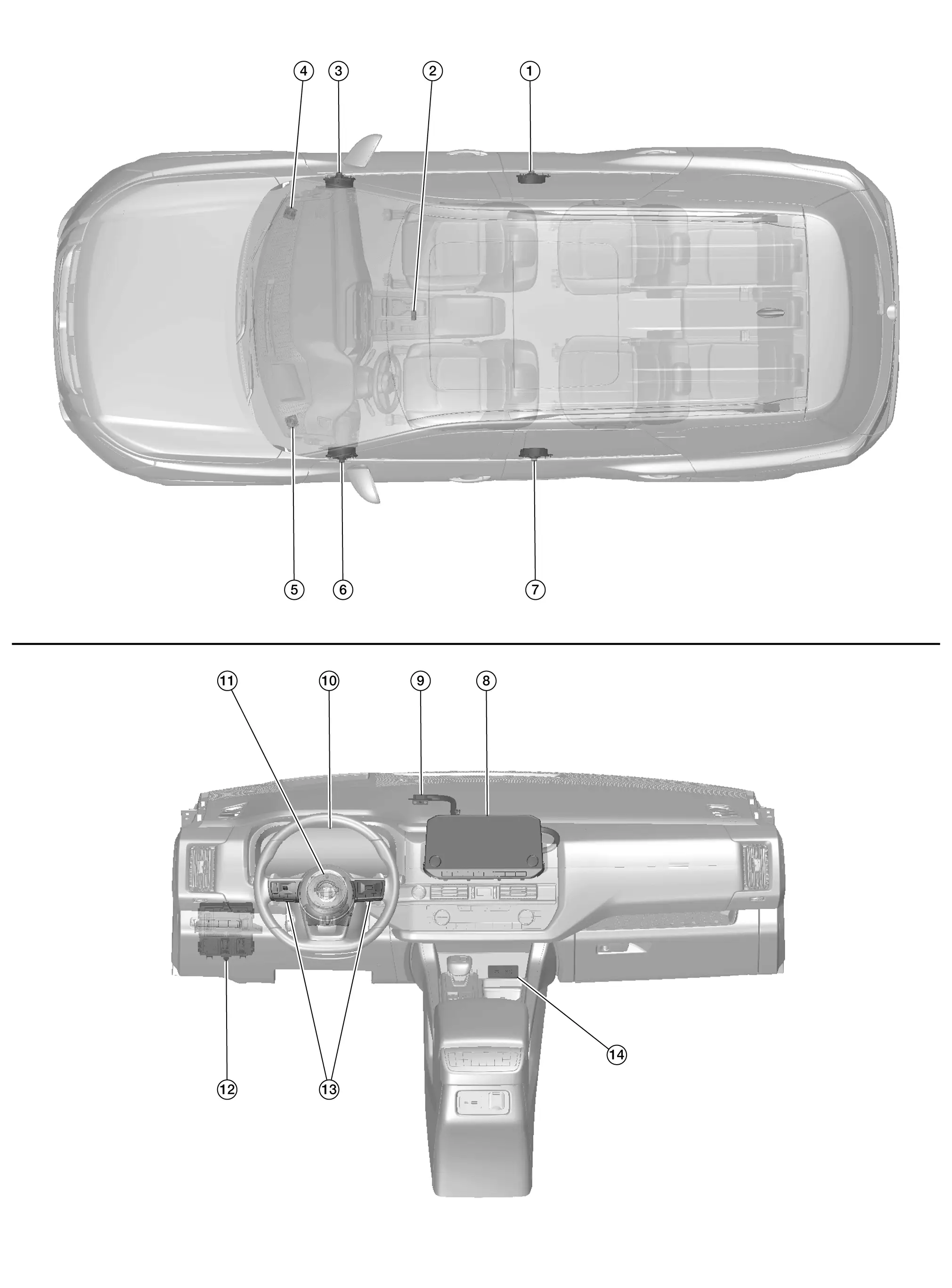
| No. | Component | Function |
|---|---|---|
| 1. | Rear door speaker RH | Refer to Speaker. |
| 2. | Microphone | Refer to Microphone. |
| 3. | Front door speaker RH | Refer to Speaker. |
| 4. | Instrument Panel tweeter RH | |
| 5. | Instrument Panel tweeter LH | |
| 6. | Front door speaker LH | |
| 7. | Rear door speaker LH | |
| 8. | AV control unit | Refer to AV Control Unit. |
| 9. | GPS antenna | Refer to Antenna and Antenna Feeder. |
| 10. | Combination meter |
Provides AV control unit with the steering switch signals via AV communication. Provides AV control unit with the following signals via CAN communication:
|
| 11. | Combination switch (spiral cable) | Provides a pass-through for the steering switch signals from the steering switches to the combination meter. |
| 12. | BCM (Body Control Module) |
Provides AV control unit with the position light request signal via CAN communication. Refer to System Description. |
| 13. | Steering switches | Refer to Steering Switches. |
| 14. | Front auxiliary input jacks | Refer to Front Auxiliary Input Jacks. |
NissanConnect With Bose® Audio System 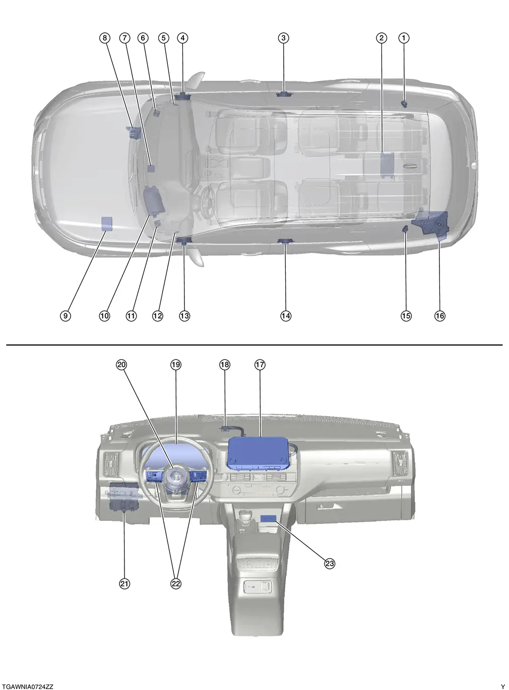
| No. | Component | Function |
|---|---|---|
| 1. | Rear side speaker RH | Refer to Speaker. |
| 2. | Bose® speaker amp. | Refer to Bose Speaker Amp.. |
| 3. | Rear door speaker RH | Refer to Speaker. |
| 4. | Front door speaker RH | |
| 5. | Front tweeter RH | |
| 6. | Instrument Panel tweeter RH | |
| 7. | Center speaker | |
| 8. | ABS (Anti-lock Braking System) actuator and electric unit (control unit) |
Provides Bose speaker amp. with the odometer signal via CAN communication. Refer to Component Parts Location for detailed component location. |
| 9. | IPDM E/R (Intelligent Power Distribution Module Engine Room) |
Provides Bose speaker amp. with the battery voltage signal via CAN communication. Refer to System Description. |
| 10. | Head up display unit (if so equipped) |
Provides AV control unit with the head up display signals via AV communication. Refer to Component Parts Location (full TFT meter) or Component Parts Location (7 inch information display meter) for detailed component location. |
| 11. | Instrument Panel tweeter LH | Refer to Speaker. |
| 12. | Front tweeter LH | |
| 13. | Front door speaker LH | |
| 14. | Rear door speaker LH | |
| 15. | Rear side speaker LH | |
| 16. | Subwoofer | |
| 17. | AV control unit | Refer to AV Control Unit. |
| 18. | GPS antenna | Refer to Antenna and Antenna Feeder. |
| 19. | Combination meter |
Provides AV control unit with the steering switch signals via AV communication. Provides AV control unit with the following signals via CAN communication:
|
| 20. | Combination switch (spiral cable) | Provides a pass-through for the steering switch signals from the steering switches to the combination meter. |
| 21. | BCM (Body Control Module) |
|
| 22. | Steering switches | Refer to Steering Switches. |
| 23. | Front auxiliary input jacks | Refer to Front Auxiliary Input Jacks. |
AV Control Unit
-
An 8-inch (without navigation) or 9-inch (with navigation) color display with multi-touch control, an AM/FM electronic tuner radio with RDS and camera controller are integrated into the AV Control unit.
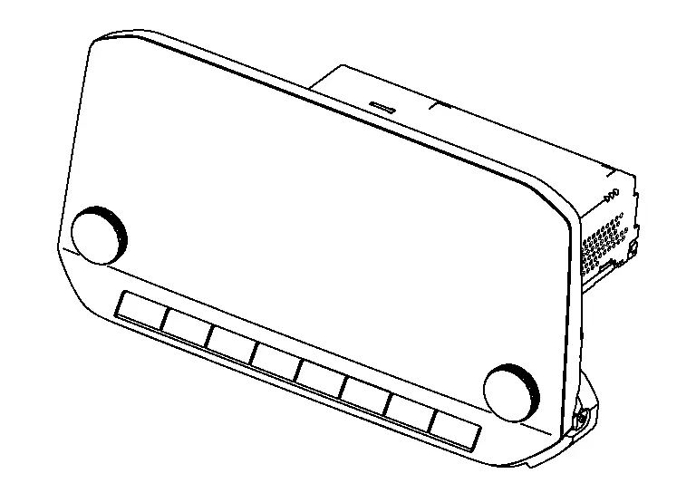
-
The color display is a high resolution monitor that includes touch panel functions.
-
Music files stored in iPod®*/USB memory can be played using the separate USB interfaces.
*: iPod® is a registered trademark of Apple, Inc. All rights reserved.
Bose Speaker Amp.
-
The Bose speaker amp. is located underneath the floor in the luggage compartment.
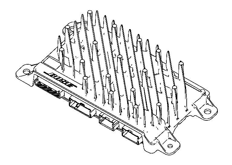
-
The Bose speaker amp. receives sound signals from the AV Control unit and outputs the signals to the speakers.
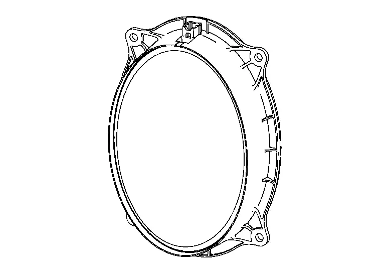
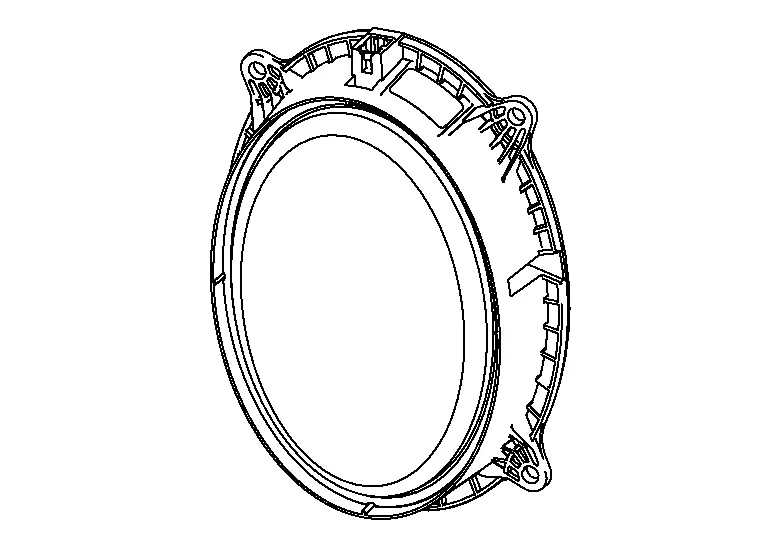
Speaker
WITHOUT BOSE AUDIO SYSTEM
Instrument Panel Tweeter
-
5.1 cm (2 in) speakers are installed in the top corners of the instrument panel assembly.

-
Sound signals generated by the AV control unit output high range sounds.
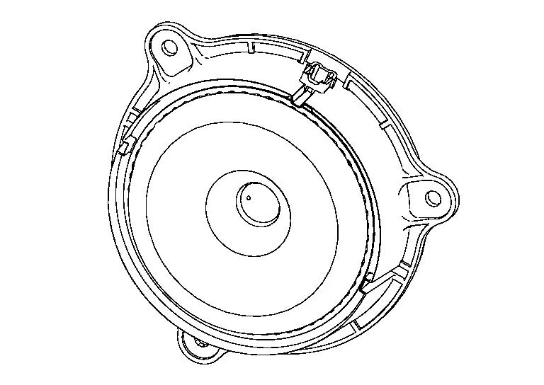
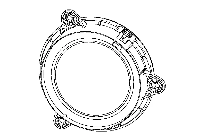
Front Door Speaker
-
15.2 x 22.9 cm (6 x 9 in) speakers are installed in the bottom of the front doors.
-
Sound signals generated by the AV control unit output low range sounds.
Rear Door Speaker
-
16.5 cm (6.5 in) speakers are installed in the bottom of the rear doors.
-
Sound signals generated by the AV control unit output mid range sounds.
WITH BOSE AUDIO SYSTEM
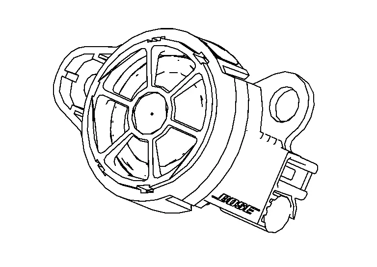
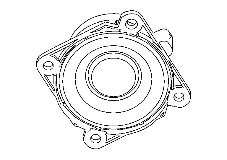
Center Speaker
-
7.6 cm (3 in) speaker is installed to the center of instrument panel.
-
Sound signals generated by the Bose speaker amp. output mid range sounds.
Instrument Panel Tweeter
-
6.35 cm (2.5 in) speakers are installed in the top corners of the instrument panel assembly.

-
Sound signals generated by the Bose speaker amp. output high range sounds.
Front Tweeter
-
2.5 cm (1 in) speakers are installed in the front pillar finishers.
-
Sound signals generated by the Bose speaker amp. output high range sounds.
Front Door Speaker
-
15.2 x 22.9 cm (6 x 9 in) speakers are installed in the bottom of the front doors.
-
Sound signals generated by the Bose speaker amp. output low range sounds.
Rear Door Speaker
-
12.7 cm (5 in) speakers are installed in the bottom of the rear doors.
-
Sound signals generated by the Bose speaker amp. output mid range sounds.
Rear Side Speaker
-
7.6 cm (3 in) speakers are installed in the luggage side lower finishers.
-
Sound signals generated by the Bose speaker amp. output mid range sounds.
SUBWOOFER
-
The subwoofer enclosure contains two 12.7 cm (5 in) speakers and is installed inside the storage box in the luggage area.
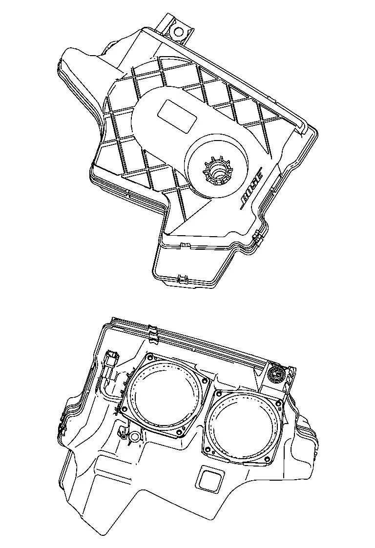
-
Sound signal is input from the Bose speaker amp. to output low range sound.
Steering Switches
-
Hands-free phone and audio operations can be performed.
-
Steering switches are connected to combination meter and switch operation signals are transmitted to combination meter.
-
Combination meter transmits steering switch signals to AV control unit via AV communication.
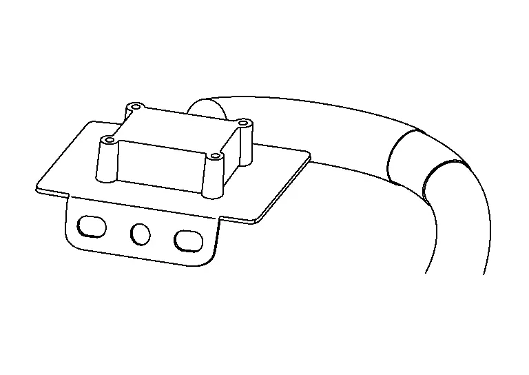
Microphone
-
The microphone is installed in the roof in the map lamp assembly.
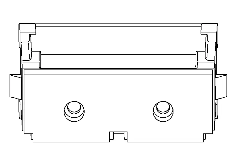
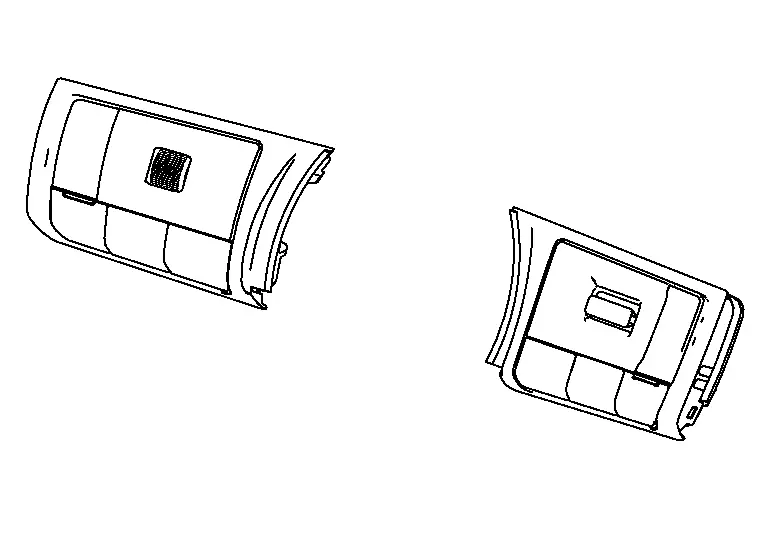
Front Auxiliary Input Jacks
-
Front auxiliary input jacks are located in the center console.
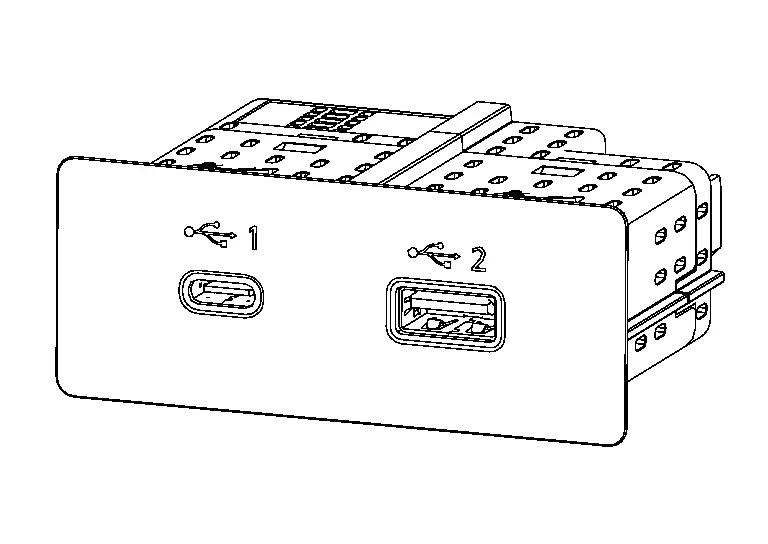
-
iPod and USB memory can be connected to the AV control unit through the USB interfaces.
Antenna and Antenna Feeder
GPS ANTENNA
-
GPS antenna is installed in the instrument panel.
-
Power is supplied from the AV control unit.
-
This antenna amplifies radio waves received from the GPS satellite and transmits the GPS signal to the AV control unit.
 NOTE:
NOTE:
An object on the instrument panel may cause the reception sensitivity to be decreased.
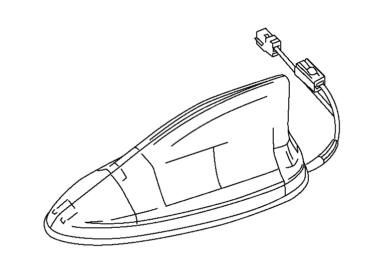
ANTENNA BASE, SATELLITE ANTENNA AND RADIO ANTENNAS
-
Antenna base is installed on the rear center of the roof.
-
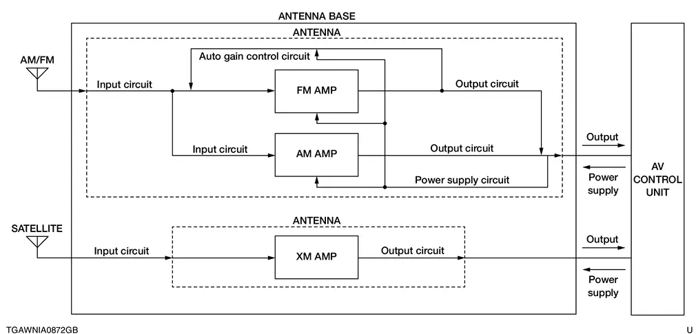
USA and Canada:
-
Antenna base incorporates the satellite radio antenna, AM/FM antenna and antenna amp.
-
Receives satellite radio waves and outputs them to AV control unit.
-
Receives AM/FM radio waves and outputs them to AV control unit.
-
The AM/FM radio main antenna path has an antenna amp. to obtain sufficient reception power.
-
-
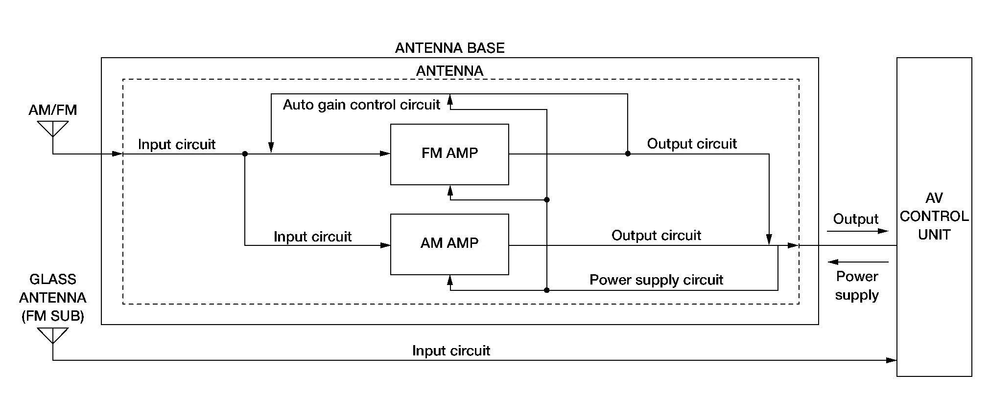
Except USA and Canada:
-
Antenna base incorporates the AM/FM antenna and antenna amp.
-
Receives AM/FM radio waves and outputs them to AV control unit.
-
Glass antenna (FM sub) receives FM radio waves and outputs them to AV control unit.
-
The AM/FM radio main antenna path has an antenna amp. to obtain sufficient reception power.
-
ANTENNA FEEDER LAYOUT
USA and Canada 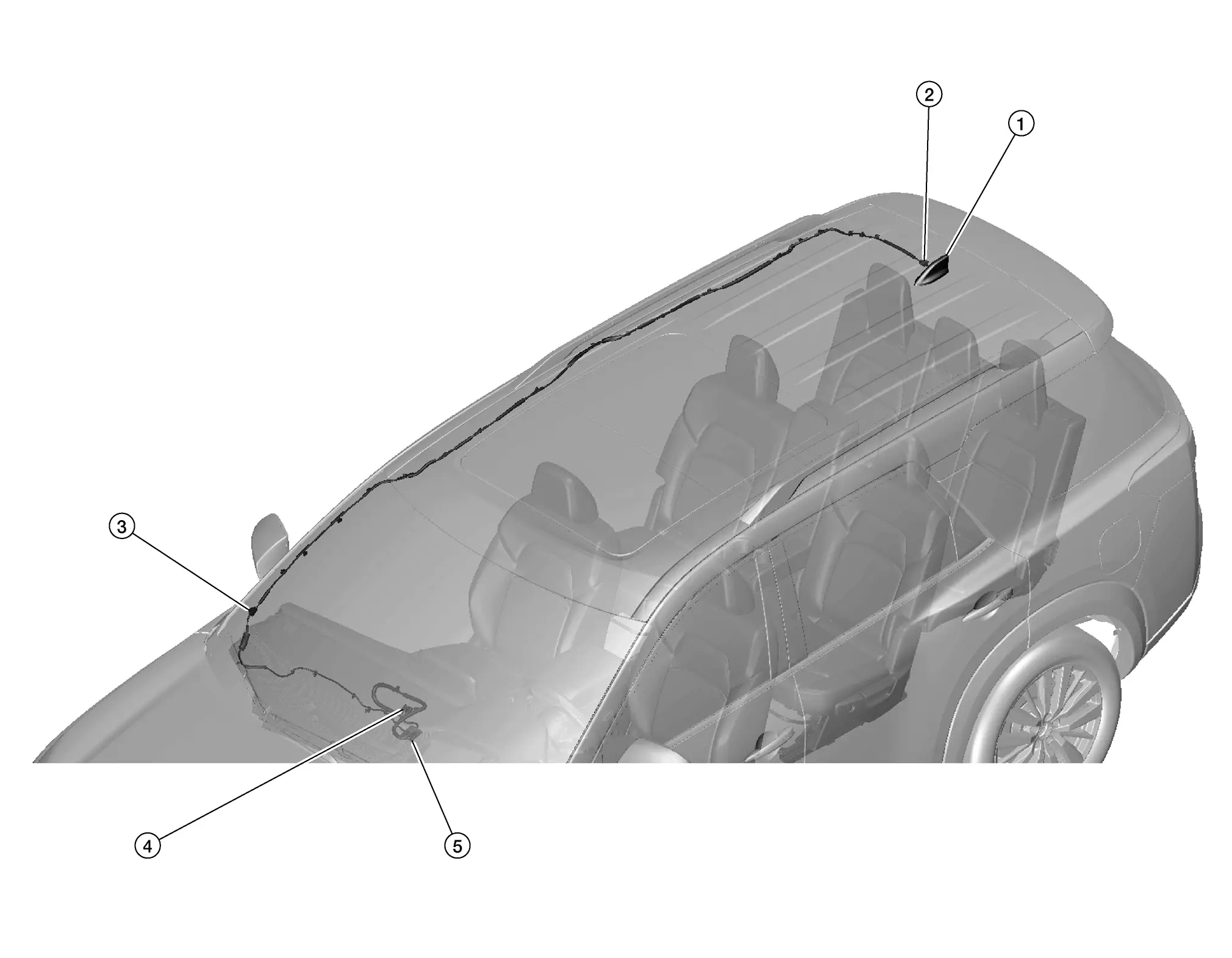
| 1. | Antenna base | 2. |
R203 (without satellite antenna) R204 (with satellite antenna) |
3. |
M207, R207 (without satellite antenna) M151, R201 (with satellite antenna) |
| 4. | M155, M156, M157 | 5. | GPS antenna |
Except USA and Canada 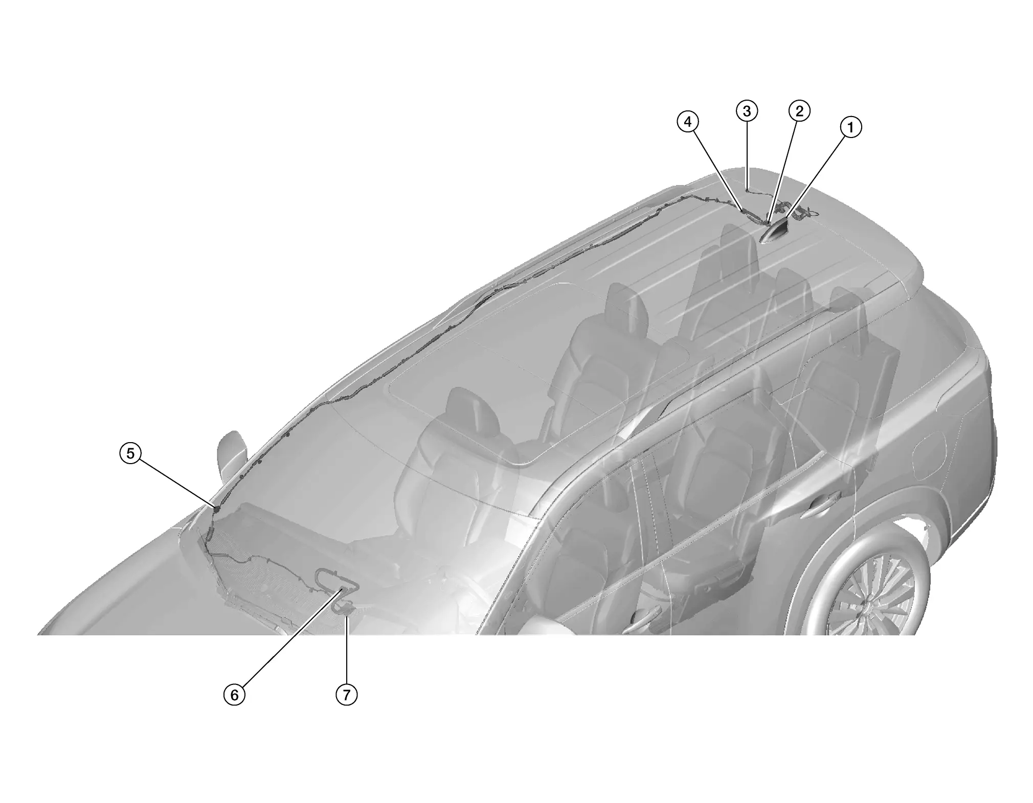
| 1. | Antenna base | 2. | R203 | 3. | D601 |
| 4. | D600, R202 | 5. | M207, R207 | 6. | M152, M155, M157 |
| 7. | GPS antenna |

Nissan Pathfinder (R53) 2022-2026 Service Manual
Contact Us
Nissan Pathfinder Info Center
Email: info@nipathfinder.com
Phone: +1 (800) 123-4567
Address: 123 Pathfinder Blvd, Nashville, TN 37214, USA
Working Hours: Mon–Fri, 9:00 AM – 5:00 PM (EST)
