Nissan Pathfinder: Audio, Visual & Navigation System - Dtc/circuit Diagnosis
Multi Av (av Control Unit) ➤ Nissan Pathfinder SUV
Audio Amp. (bose Speaker Amp.) Nissan Pathfinder Fifth generation
B1a01 Front Left Door Woofer Out
DTC Description
DTC DETECTION LOGIC
| DTC No. |
CONSULT screen terms (Trouble diagnosis content) | DTC detection condition | ||
|---|---|---|---|---|
| B1A01–13 |
Front left door woofer out (Front door speaker LH and front tweeter LH) |
[OPEN] | Diagnosis condition | Ignition switch ON. |
| Signal (terminal) |
|
|||
| Threshold | — | |||
| Diagnosis delay time | 30 seconds or more | |||
| B1A01–1A | [SHORT] | Diagnosis condition | Ignition switch ON. | |
| Signal (terminal) |
|
|||
| Threshold | — | |||
| Diagnosis delay time | 30 seconds or more | |||
| B1A01–11 | [GND–SHORT] | Diagnosis condition | Ignition switch ON. | |
| Signal (terminal) |
|
|||
| Threshold | — | |||
| Diagnosis delay time | 30 seconds or more | |||
| B1A01–12 | [VB–SHOR] | Diagnosis condition | Ignition switch ON. | |
| Signal (terminal) |
|
|||
| Threshold | — | |||
| Diagnosis delay time | 30 seconds or more | |||
POSSIBLE CAUSE
-
FR DOOR LH+ open, short, short to ground, short to voltage
-
FR DOOR LH− open, short, short to ground, short to voltage
-
Front door speaker LH
-
Front tweeter LH
-
Bose speaker amp.
FAIL-SAFE
-
Failure type byte 11, 12 and 1A:
-
Front door speaker LH inoperative
-
Front tweeter LH inoperative
-
-
Failure type byte 13: front door speaker LH inoperative
Confirmation Procedure
PERFORM DTC CONFIRMATION PROCEDURE
 CONSULT
-
Ignition switch ON.
-
Ignition switch OFF and wait for 4 minutes.
-
Ignition switch ON and wait at least 1 minute or more.
-
Select “Self Diagnostic Result” mode of “Audio amp.”.
-
Check DTC.
Is DTC B1A01 detected?
YES>>Proceed to Diagnosis Procedure.
NO>>To check malfunction symptom before repair: Refer to Intermittent Incident.
NO>>Confirmation after repair: Inspection End.
Diagnosis Procedure
DETERMINE MALFUNCTION TYPE
 CONSULT
-
Ignition switch ON.
-
Ignition switch OFF and wait for 4 minutes.
-
Ignition switch ON and wait at least 1 minute or more.
-
Select “Self Diagnostic Result” mode of “Audio amp.”.
-
Check DTC.
Is DTC B1A01–11, 12, 13 or 1A detected?
YES>>13 [OPEN], or 11 [GND–SHORT] – GO TO 2.
YES>>1A [SHORT] – GO TO 3.
YES>>12 [VB–SHOR] – GO TO 4.
NO>>Refer to Intermittent Incident.
CHECK SOUND SIGNAL CIRCUITS FOR OPEN OR SHORT TO GROUND
-
Ignition switch OFF.
-
Disconnect Bose speaker amp. connector B146, front door speaker LH connector and front tweeter LH connector.
-
Check the continuity between Bose speaker amp. connector B146 and front door speaker LH connector D13.
Bose speaker amp. Front door speaker LH Continuity Connector Terminal Connector Terminal B146 66 D13 1 Yes 65 2 -
Check the continuity between Bose speaker amp. connector B146 and ground.
Bose speaker amp. Continuity Connector Terminal Ground B146 66 — No 65
Is the inspection result normal?
YES>>GO TO 5.
NO>>Repair or replace harness or connectors.
CHECK SOUND SIGNAL CIRCUITS FOR SHORT
-
Ignition switch OFF.
-
Disconnect Bose speaker amp. connector B146, front door speaker LH connector and front tweeter LH connector.
-
Check the continuity between the terminals of Bose speaker amp. connector B146.
Bose speaker amp. Continuity Connector Terminal B146 66 65 No
Is the inspection result normal?
YES>>GO TO 5.
NO>>Repair or replace harness or connectors.
CHECK SOUND SIGNAL CIRCUIT FOR SHORT TO POWER SUPPLY
-
Ignition switch OFF.
-
Disconnect Bose speaker amp. connector B146, front door speaker LH connector and front tweeter LH connector.
-
Ignition switch ON.
-
Check the voltage between Bose speaker amp. connector B146 and ground.
Bose speaker amp. Ground Voltage
Approx.Connector Terminal B146 66 — 0 V 65
Is the inspection result normal?
YES>>GO TO 5.
NO>>Repair or replace harness or connectors.
CHECK FRONT LH SPEAKER SIGNAL
-
Connect Bose speaker amp. connector B146, front door speaker LH connector and front tweeter LH connector.
-
Ignition switch ON.
-
Push AV control unit POWER switch.
-
Check signal between the terminals of Bose speaker amp. connector B146.
Bose speaker amp. Condition Reference value Connector (+) (−) Terminal Terminal B146 66 65 Audio signal output 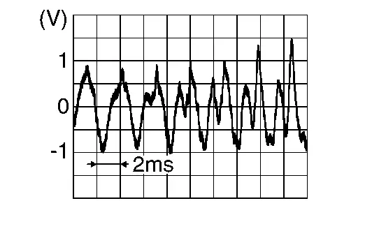
Is the inspection result normal?
YES>>Replace front door speaker LH or front tweeter LH. Refer to Removal and Installation (front door speaker) or Removal and Installation (front tweeter).
NO>>Replace Bose speaker amp. Refer to Removal and Installation.
B1a05 Front Right Door Woofer Out
DTC Description
DTC DETECTION LOGIC
| DTC No. |
CONSULT screen terms (Trouble diagnosis content) | DTC detection condition | ||
|---|---|---|---|---|
| B1A05–13 |
Front right door woofer out (Front door speaker RH and front tweeter RH) |
[OPEN] | Diagnosis condition | Ignition switch ON. |
| Signal (terminal) |
|
|||
| Threshold | — | |||
| Diagnosis delay time | 30 seconds or more | |||
| B1A05–1A | [SHORT] | Diagnosis condition | Ignition switch ON. | |
| Signal (terminal) |
|
|||
| Threshold | — | |||
| Diagnosis delay time | 30 seconds or more | |||
| B1A05–11 | [GND–SHORT] | Diagnosis condition | Ignition switch ON. | |
| Signal (terminal) |
|
|||
| Threshold | — | |||
| Diagnosis delay time | 30 seconds or more | |||
| B1A05–12 | [VB–SHOR] | Diagnosis condition | Ignition switch ON. | |
| Signal (terminal) |
|
|||
| Threshold | — | |||
| Diagnosis delay time | 30 seconds or more | |||
POSSIBLE CAUSE
-
FR DOOR RH+ open, short, short to ground, short to voltage
-
FR DOOR RH− open, short, short to ground, short to voltage
-
Front door speaker RH
-
Front tweeter RH
-
Bose speaker amp.
FAIL-SAFE
-
Failure type byte 11, 12 and 1A:
-
Front door speaker RH inoperative
-
Front tweeter RH inoperative
-
-
Failure type byte 13: front door speaker RH inoperative
Confirmation Procedure
PERFORM DTC CONFIRMATION PROCEDURE
 CONSULT
-
Ignition switch ON.
-
Ignition switch OFF and wait for 4 minutes.
-
Ignition switch ON and wait at least 1 minute or more.
-
Select “Self Diagnostic Result” mode of “Audio amp.”.
-
Check DTC.
Is DTC B1A05 detected?
YES>>Proceed to Diagnosis Procedure.
NO>>To check malfunction symptom before repair: Refer to Intermittent Incident.
NO>>Confirmation after repair: Inspection End.
Diagnosis Procedure
DETERMINE MALFUNCTION TYPE
 CONSULT
-
Ignition switch ON.
-
Ignition switch OFF and wait for 4 minutes.
-
Ignition switch ON and wait at least 1 minute or more.
-
Select “Self Diagnostic Result” mode of “Audio amp.”.
-
Check DTC.
Is DTC B1A05–11, 12, 13 or 1A detected?
YES>>13 [OPEN], or 11 [GND–SHORT] – GO TO 2.
YES>>1A [SHORT] – GO TO 3.
YES>>12 [VB–SHOR] – GO TO 4.
NO>>Refer to Intermittent Incident.
CHECK SOUND SIGNAL CIRCUITS FOR OPEN OR SHORT TO GROUND
-
Ignition switch OFF.
-
Disconnect Bose speaker amp. connector B146, front door speaker RH connector and front tweeter RH connector.
-
Check the continuity between Bose speaker amp. connector B146 and front door speaker RH connector D113.
Bose speaker amp. Front door speaker RH Continuity Connector Terminal Connector Terminal B146 67 D113 1 Yes 60 2 -
Check the continuity between Bose speaker amp. connector B146 and ground.
Bose speaker amp. Continuity Connector Terminal Ground B146 67 — No 60
Is the inspection result normal?
YES>>GO TO 5.
NO>>Repair or replace harness or connectors.
CHECK SOUND SIGNAL CIRCUITS FOR SHORT
-
Ignition switch OFF.
-
Disconnect Bose speaker amp. connector B146, front door speaker RH connector and front tweeter RH connector.
-
Check the continuity between the terminals of Bose speaker amp. connector B146.
Bose speaker amp. Continuity Connector Terminal B146 67 60 No
Is the inspection result normal?
YES>>GO TO 5.
NO>>Repair or replace harness or connectors.
CHECK SOUND SIGNAL CIRCUIT FOR SHORT TO POWER SUPPLY
-
Ignition switch OFF.
-
Disconnect Bose speaker amp. connector B146, front door speaker RH connector and front tweeter RH connector.
-
Ignition switch ON.
-
Check the voltage between Bose speaker amp. connector B146 and ground.
Bose speaker amp. Ground Voltage
Approx.Connector Terminal B146 67 — 0 V 60
Is the inspection result normal?
YES>>GO TO 5.
NO>>Repair or replace harness or connectors.
CHECK FRONT RH SPEAKER SIGNAL
-
Connect Bose speaker amp. connector B146, front door speaker RH connector and front tweeter RH connector.
-
Ignition switch ON.
-
Push AV control unit POWER switch.
-
Check signal between the terminals of Bose speaker amp. connector B146.
Bose speaker amp. Condition Reference value Connector (+) (−) Terminal Terminal B146 67 60 Audio signal output 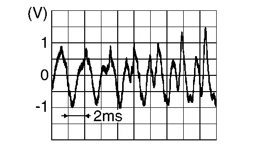
Is the inspection result normal?
YES>>Replace front door speaker RH or front tweeter RH. Refer to Removal and Installation (front door speaker) or Removal and Installation (front tweeter).
NO>>Replace Bose speaker amp. Refer to Removal and Installation.
B1a0a Front Instrument Left Squawker Out
DTC Description
DTC DETECTION LOGIC
| DTC No. |
CONSULT screen terms (Trouble diagnosis content) | DTC detection condition | ||
|---|---|---|---|---|
| B1A0A–13 |
Front instrument left squawker out (Instrument panel tweeter LH) |
[OPEN] | Diagnosis condition | Ignition switch ON. |
| Signal (terminal) |
|
|||
| Threshold | — | |||
| Diagnosis delay time | 30 seconds or more | |||
| B1A0A–1A | [SHORT] | Diagnosis condition | Ignition switch ON. | |
| Signal (terminal) |
|
|||
| Threshold | — | |||
| Diagnosis delay time | 30 seconds or more | |||
| B1A0A–11 | [GND–SHORT] | Diagnosis condition | Ignition switch ON. | |
| Signal (terminal) |
|
|||
| Threshold | — | |||
| Diagnosis delay time | 30 seconds or more | |||
| B1A0A–12 | [VB–SHOR] | Diagnosis condition | Ignition switch ON. | |
| Signal (terminal) |
|
|||
| Threshold | — | |||
| Diagnosis delay time | 30 seconds or more | |||
POSSIBLE CAUSE
-
FR INST LH+ open, short, short to ground, short to voltage
-
FR INST LH− open, short, short to ground, short to voltage
-
Instrument panel tweeter LH
-
Bose speaker amp.
FAIL-SAFE
Instrument panel tweeter LH is inoperative
Confirmation Procedure
PERFORM DTC CONFIRMATION PROCEDURE
 CONSULT
-
Ignition switch ON.
-
Ignition switch OFF and wait for 4 minutes.
-
Ignition switch ON and wait at least 1 minute or more.
-
Select “Self Diagnostic Result” mode of “Audio amp.”.
-
Check DTC.
Is DTC B1A0A detected?
YES>>Proceed to Diagnosis Procedure.
NO>>To check malfunction symptom before repair: Refer to Intermittent Incident.
NO>>Confirmation after repair: Inspection End.
Diagnosis Procedure
DETERMINE MALFUNCTION TYPE
 CONSULT
-
Ignition switch ON.
-
Ignition switch OFF and wait for 4 minutes.
-
Ignition switch ON and wait at least 1 minute or more.
-
Select “Self Diagnostic Result” mode of “Audio amp.”.
-
Check DTC.
Is DTC B1A0A–11, 12, 13 or 1A detected?
YES>>13 [OPEN], or 11 [GND–SHORT] – GO TO 2.
YES>>1A [SHORT] – GO TO 3.
YES>>12 [VB–SHOR] – GO TO 4.
NO>>Refer to Intermittent Incident.
CHECK SOUND SIGNAL CIRCUITS FOR OPEN OR SHORT TO GROUND
-
Ignition switch OFF.
-
Disconnect Bose speaker amp. connector B130 and instrument panel tweeter LH connector.
-
Check the continuity between Bose speaker amp. connector B130 and instrument panel tweeter LH connector M62.
Bose speaker amp. Instrument panel tweeter LH Continuity Connector Terminal Connector Terminal B130 43 M62 1 Yes 50 2 -
Check the continuity between Bose speaker amp. connector B130 and ground.
Bose speaker amp. Continuity Connector Terminal Ground B130 43 — No 50
Is the inspection result normal?
YES>>GO TO 5.
NO>>Repair or replace harness or connectors.
CHECK SOUND SIGNAL CIRCUITS FOR SHORT
-
Ignition switch OFF.
-
Disconnect Bose speaker amp. connector B130 and instrument panel tweeter LH connector.
-
Check the continuity between the terminals of Bose speaker amp. connector B130.
Bose speaker amp. Continuity Connector Terminal B130 43 50 No
Is the inspection result normal?
YES>>GO TO 5.
NO>>Repair or replace harness or connectors.
CHECK SOUND SIGNAL CIRCUIT FOR SHORT TO POWER SUPPLY
-
Ignition switch OFF.
-
Disconnect Bose speaker amp. connector B130 and instrument panel tweeter LH connector.
-
Ignition switch ON.
-
Check the voltage between Bose speaker amp. connector B130 and ground.
Bose speaker amp. Ground Voltage
Approx.Connector Terminal B130 43 — 0 V 50
Is the inspection result normal?
YES>>GO TO 5.
NO>>Repair or replace harness or connectors.
CHECK INSTRUMENT PANEL TWEETER LH SIGNAL
-
Connect Bose speaker amp. connector B130 and instrument panel tweeter LH connector.
-
Ignition switch ON.
-
Push AV control unit POWER switch.
-
Check signal between the terminals of Bose speaker amp. connector B130.
Bose speaker amp. Condition Reference value Connector (+) (−) Terminal Terminal B130 43 50 Audio signal output 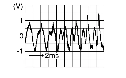
Is the inspection result normal?
YES>>Replace instrument panel tweeter LH. Refer to Removal and Installation.
NO>>Replace Bose speaker amp. Refer to Removal and Installation.
B1a0e Front Instrument Center Squawker Out
DTC Description
DTC DETECTION LOGIC
| DTC No. |
CONSULT screen terms (Trouble diagnosis content) | DTC detection condition | ||
|---|---|---|---|---|
| B1A0E–13 |
Front instrument center squawker out (Center speaker) |
[OPEN] | Diagnosis condition | Ignition switch ON. |
| Signal (terminal) |
|
|||
| Threshold | — | |||
| Diagnosis delay time | 30 seconds or more | |||
| B1A0E–1A | [SHORT] | Diagnosis condition | Ignition switch ON. | |
| Signal (terminal) |
|
|||
| Threshold | — | |||
| Diagnosis delay time | 30 seconds or more | |||
| B1A0E–11 | [GND–SHORT] | Diagnosis condition | Ignition switch ON. | |
| Signal (terminal) |
|
|||
| Threshold | — | |||
| Diagnosis delay time | 30 seconds or more | |||
| B1A0E–12 | [VB–SHOR] | Diagnosis condition | Ignition switch ON. | |
| Signal (terminal) |
|
|||
| Threshold | — | |||
| Diagnosis delay time | 30 seconds or more | |||
POSSIBLE CAUSE
-
INST SP CENT+ open, short, short to ground, short to voltage
-
INST SP CENT− open, short, short to ground, short to voltage
-
Center speaker
-
Bose speaker amp.
FAIL-SAFE
Center speaker is inoperative
Confirmation Procedure
PERFORM DTC CONFIRMATION PROCEDURE
 CONSULT
-
Ignition switch ON.
-
Ignition switch OFF and wait for 4 minutes.
-
Ignition switch ON and wait at least 1 minute or more.
-
Select “Self Diagnostic Result” mode of “Audio amp.”.
-
Check DTC.
Is DTC B1A0E detected?
YES>>Proceed to DTC Diagnosis Procedure.
NO>>To check malfunction symptom before repair: Refer to Intermittent Incident.
NO>>Confirmation after repair: Inspection End.
DTC Diagnosis Procedure
DETERMINE MALFUNCTION TYPE
 CONSULT
-
Ignition switch ON.
-
Ignition switch OFF and wait for 4 minutes.
-
Ignition switch ON and wait at least 1 minute or more.
-
Select “Self Diagnostic Result” mode of “Audio amp.”.
-
Check DTC.
Is DTC B1A0E–11, 12, 13 or 1A detected?
YES>>13 [OPEN], or 11 [GND–SHORT] – GO TO 2.
YES>>1A [SHORT] – GO TO 3.
YES>>12 [VB–SHOR] – GO TO 4.
NO>>Refer to Intermittent Incident.
CHECK SOUND SIGNAL CIRCUITS FOR OPEN OR SHORT TO GROUND
-
Ignition switch OFF.
-
Disconnect Bose speaker amp. connector B130 and center speaker connector.
-
Check the continuity between Bose speaker amp. connector B130 and center speaker connector M279.
Bose speaker amp. Center speaker Continuity Connector Terminal Connector Terminal B130 46 M279 1 Yes 55 2 -
Check the continuity between Bose speaker amp. connector B130 and ground.
Bose speaker amp. Continuity Connector Terminal Ground B130 46 — No 55
Is the inspection result normal?
YES>>GO TO 5.
NO>>Repair or replace harness or connectors.
CHECK SOUND SIGNAL CIRCUITS FOR SHORT
-
Ignition switch OFF.
-
Disconnect Bose speaker amp. connector B130 and center speaker connector.
-
Check the continuity between the terminals of Bose speaker amp. connector B130.
Bose speaker amp. Continuity Connector Terminal B130 46 55 No
Is the inspection result normal?
YES>>GO TO 5.
NO>>Repair or replace harness or connectors.
CHECK SOUND SIGNAL CIRCUIT FOR SHORT TO POWER SUPPLY
-
Ignition switch OFF.
-
Disconnect Bose speaker amp. connector B130 and center speaker connector.
-
Ignition switch ON.
-
Check the voltage between Bose speaker amp. connector B130 and ground.
Bose speaker amp. Ground Voltage
Approx.Connector Terminal B130 46 — 0 V 55
Is the inspection result normal?
YES>>GO TO 5.
NO>>Repair or replace harness or connectors.
CHECK CENTER SPEAKER SIGNAL
-
Connect Bose speaker amp. connector B130 and center speaker connector.
-
Ignition switch ON.
-
Push AV control unit POWER switch.
-
Check signal between the terminals of Bose speaker amp. connector B130.
Bose speaker amp. Condition Reference value Connector (+) (−) Terminal Terminal B130 46 55 Audio signal output 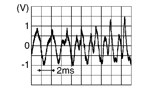
Is the inspection result normal?
YES>>Replace center speaker. Refer to Removal and Installation.
NO>>Replace Bose speaker amp. Refer to Removal and Installation.
B1a12 Front Instrument Right Squawker Out
DTC Description
DTC DETECTION LOGIC
| DTC No. |
CONSULT screen terms (Trouble diagnosis content) | DTC detection condition | ||
|---|---|---|---|---|
| B1A12–13 |
Front instrument right squawker out (Instrument panel tweeter RH) |
[OPEN] | Diagnosis condition | Ignition switch ON. |
| Signal (terminal) |
|
|||
| Threshold | — | |||
| Diagnosis delay time | 30 seconds or more | |||
| B1A12–1A | [SHORT] | Diagnosis condition | Ignition switch ON. | |
| Signal (terminal) |
|
|||
| Threshold | — | |||
| Diagnosis delay time | 30 seconds or more | |||
| B1A12–11 | [GND–SHORT] | Diagnosis condition | Ignition switch ON. | |
| Signal (terminal) |
|
|||
| Threshold | — | |||
| Diagnosis delay time | 30 seconds or more | |||
| B1A12–12 | [VB–SHOR] | Diagnosis condition | Ignition switch ON. | |
| Signal (terminal) |
|
|||
| Threshold | — | |||
| Diagnosis delay time | 30 seconds or more | |||
POSSIBLE CAUSE
-
FR INST RH+ open, short, short to ground, short to voltage
-
FR INST RH− open, short, short to ground, short to voltage
-
Instrument panel tweeter RH
-
Bose speaker amp.
FAIL-SAFE
Instrument panel tweeter RH is inoperative
Confirmation Procedure
PERFORM DTC CONFIRMATION PROCEDURE
 CONSULT
-
Ignition switch ON.
-
Ignition switch OFF and wait for 4 minutes.
-
Ignition switch ON and wait at least 1 minute or more.
-
Select “Self Diagnostic Result” mode of “Audio amp.”.
-
Check DTC.
Is DTC B1A12 detected?
YES>>Proceed to Diagnosis Procedure.
NO>>To check malfunction symptom before repair: Refer to Intermittent Incident.
NO>>Confirmation after repair: Inspection End.
Diagnosis Procedure
DETERMINE MALFUNCTION TYPE
 CONSULT
-
Ignition switch ON.
-
Ignition switch OFF and wait for 4 minutes.
-
Ignition switch ON and wait at least 1 minute or more.
-
Select “Self Diagnostic Result” mode of “Audio amp.”.
-
Check DTC.
Is DTC B1A12–11, 12, 13 or 1A detected?
YES>>13 [OPEN], or 11 [GND–SHORT] – GO TO 2.
YES>>1A [SHORT] – GO TO 3.
YES>>12 [VB–SHOR] – GO TO 4.
NO>>Refer to Intermittent Incident.
CHECK SOUND SIGNAL CIRCUITS FOR OPEN OR SHORT TO GROUND
-
Ignition switch OFF.
-
Disconnect Bose speaker amp. connector B130 and instrument panel tweeter RH connector.
-
Check the continuity between Bose speaker amp. connector B130 and instrument panel tweeter RH connector M73.
Bose speaker amp. Instrument panel tweeter RH Continuity Connector Terminal Connector Terminal B130 51 M73 1 Yes 52 2 -
Check the continuity between Bose speaker amp. connector B130 and ground.
Bose speaker amp. Continuity Connector Terminal Ground B130 51 — No 52
Is the inspection result normal?
YES>>GO TO 5.
NO>>Repair or replace harness or connectors.
CHECK SOUND SIGNAL CIRCUITS FOR SHORT
-
Ignition switch OFF.
-
Disconnect Bose speaker amp. connector B130 and instrument panel tweeter RH connector.
-
Check the continuity between the terminals of Bose speaker amp. connector B130.
Bose speaker amp. Continuity Connector Terminal B130 51 52 No
Is the inspection result normal?
YES>>GO TO 5.
NO>>Repair or replace harness or connectors.
CHECK SOUND SIGNAL CIRCUIT FOR SHORT TO POWER SUPPLY
-
Ignition switch OFF.
-
Disconnect Bose speaker amp. connector B130 and instrument panel tweeter RH connector.
-
Ignition switch ON.
-
Check the voltage between Bose speaker amp. connector B130 and ground.
Bose speaker amp. Ground Voltage
Approx.Connector Terminal B130 51 — 0 V 52
Is the inspection result normal?
YES>>GO TO 5.
NO>>Repair or replace harness or connectors.
CHECK INSTRUMENT PANEL TWEETER RH SIGNAL
-
Connect Bose speaker amp. connector B130 and instrument panel tweeter RH connector.
-
Ignition switch ON.
-
Push AV control unit POWER switch.
-
Check signal between the terminals of Bose speaker amp. connector B130.
Bose speaker amp. Condition Reference value Connector (+) (−) Terminal Terminal B130 51 52 Audio signal output 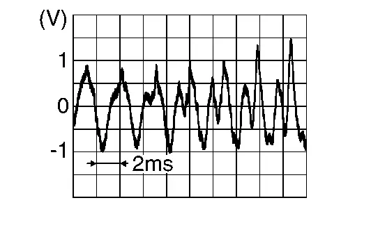
Is the inspection result normal?
YES>>Replace instrument panel tweeter RH. Refer to Removal and Installation.
NO>>Replace Bose speaker amp. Refer to Removal and Installation.
B1a2f Front Left Pillar Tweeter Out
DTC Description
DTC DETECTION LOGIC
| DTC No. |
CONSULT screen terms (Trouble diagnosis content) | DTC detection condition | ||
|---|---|---|---|---|
| B1A2F–13 |
Front left pillar tweeter out (Front tweeter LH) |
[OPEN] | Diagnosis condition | Ignition switch ON. |
| Signal (terminal) |
|
|||
| Threshold | — | |||
| Diagnosis delay time | 30 seconds or more | |||
POSSIBLE CAUSE
-
FR DOOR LH+ open
-
FR DOOR LH− open
-
Front tweeter LH
-
Bose speaker amp.
FAIL-SAFE
Front tweeter LH inoperative
Confirmation Procedure
PERFORM DTC CONFIRMATION PROCEDURE
 CONSULT
-
Ignition switch ON.
-
Ignition switch OFF and wait for 4 minutes.
-
Ignition switch ON and wait at least 1 minute or more.
-
Select “Self Diagnostic Result” mode of “Audio amp.”.
-
Check DTC.
Is DTC B1A2F detected?
YES>>Proceed to Diagnosis Procedure.
NO>>To check malfunction symptom before repair: Refer to Intermittent Incident.
NO>>Confirmation after repair: Inspection End.
Diagnosis Procedure
CHECK SOUND SIGNAL CIRCUITS FOR OPEN
-
Ignition switch OFF.
-
Disconnect Bose speaker amp. connector B146 and front tweeter LH connector.
-
Check the continuity between Bose speaker amp. connector B146 and front tweeter LH connector M109.
Bose speaker amp. Front tweeter LH Continuity Connector Terminal Connector Terminal B146 66 M109 1 Yes 65 2
Is the inspection result normal?
YES>>GO TO 5.
NO>>Repair or replace harness or connectors.
CHECK FRONT LH SPEAKER SIGNAL
-
Connect Bose speaker amp. connector B146 and front tweeter LH connector.
-
Ignition switch ON.
-
Push AV control unit POWER switch.
-
Check signal between the terminals of Bose speaker amp. connector B146.
Bose speaker amp. Condition Reference value Connector (+) (−) Terminal Terminal B146 66 65 Audio signal output 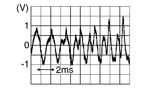
Is the inspection result normal?
YES>>Replace front tweeter LH. Refer to Removal and Installation.
NO>>Replace Bose speaker amp. Refer to Removal and Installation.
B1a33 Front Right Pillar Tweeter Out
DTC Description
DTC DETECTION LOGIC
| DTC No. |
CONSULT screen terms (Trouble diagnosis content) | DTC detection condition | ||
|---|---|---|---|---|
| B1A33–13 |
Front right pillar tweeter out (Front tweeter RH) |
[OPEN] | Diagnosis condition | Ignition switch ON. |
| Signal (terminal) |
|
|||
| Threshold | — | |||
| Diagnosis delay time | 30 seconds or more | |||
POSSIBLE CAUSE
-
FR DOOR RH+ open
-
FR DOOR RH− open
-
Front tweeter RH
-
Bose speaker amp.
FAIL-SAFE
Front tweeter RH inoperative
Confirmation Procedure
PERFORM DTC CONFIRMATION PROCEDURE
 CONSULT
-
Ignition switch ON.
-
Ignition switch OFF and wait for 4 minutes.
-
Ignition switch ON and wait at least 1 minute or more.
-
Select “Self Diagnostic Result” mode of “Audio amp.”.
-
Check DTC.
Is DTC B1A33 detected?
YES>>Proceed to Diagnosis Procedure.
NO>>To check malfunction symptom before repair: Refer to Intermittent Incident.
NO>>Confirmation after repair: Inspection End.
Diagnosis Procedure
CHECK SOUND SIGNAL CIRCUITS FOR OPEN
-
Ignition switch OFF.
-
Disconnect Bose speaker amp. connector B146 and front tweeter RH connector.
-
Check the continuity between Bose speaker amp. connector B146 and front tweeter RH connector M111.
Bose speaker amp. Front tweeter RH Continuity Connector Terminal Connector Terminal B146 67 M111 1 Yes 60 2
Is the inspection result normal?
YES>>GO TO 5.
NO>>Repair or replace harness or connectors.
CHECK FRONT RH SPEAKER SIGNAL
-
Connect Bose speaker amp. connector B146 and front tweeter RH connector.
-
Ignition switch ON.
-
Push AV control unit POWER switch.
-
Check signal between the terminals of Bose speaker amp. connector B146.
Bose speaker amp. Condition Reference value Connector (+) (−) Terminal Terminal B146 67 60 Audio signal output 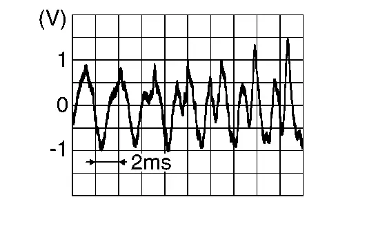
Is the inspection result normal?
YES>>Replace front tweeter RH. Refer to Removal and Installation.
NO>>Replace Bose speaker amp. Refer to Removal and Installation.
B1a4c Rl-Door Speaker Out
DTC Description
DTC DETECTION LOGIC
| DTC No. |
CONSULT screen terms (Trouble diagnosis content) | DTC detection condition | ||
|---|---|---|---|---|
| B1A4C–13 |
RL-DOOR speaker OUT (Rear door speaker LH) |
[OPEN] | Diagnosis condition | Ignition switch ON. |
| Signal (terminal) |
|
|||
| Threshold | — | |||
| Diagnosis delay time | 30 seconds or more | |||
| B1A4C–1A | [SHORT] | Diagnosis condition | Ignition switch ON. | |
| Signal (terminal) |
|
|||
| Threshold | — | |||
| Diagnosis delay time | 30 seconds or more | |||
| B1A4C–11 | [GND–SHORT] | Diagnosis condition | Ignition switch ON. | |
| Signal (terminal) |
|
|||
| Threshold | — | |||
| Diagnosis delay time | 30 seconds or more | |||
| B1A4C–12 | [VB–SHOR] | Diagnosis condition | Ignition switch ON. | |
| Signal (terminal) |
|
|||
| Threshold | — | |||
| Diagnosis delay time | 30 seconds or more | |||
POSSIBLE CAUSE
-
RR DR LH+ open, short, short to ground, short to voltage
-
RR DR LH− open, short, short to ground, short to voltage
-
Rear door speaker LH
-
Bose speaker amp.
FAIL-SAFE
Rear door speaker LH is inoperative
Confirmation Procedure
PERFORM DTC CONFIRMATION PROCEDURE
 CONSULT
-
Ignition switch ON.
-
Ignition switch OFF and wait for 4 minutes.
-
Ignition switch ON and wait at least 1 minute or more.
-
Select “Self Diagnostic Result” mode of “Audio amp.”.
-
Check DTC.
Is DTC B1A4C detected?
YES>>Proceed to Diagnosis Procedure.
NO>>To check malfunction symptom before repair: Refer to Intermittent Incident.
NO>>Confirmation after repair: Inspection End.
Diagnosis Procedure
DETERMINE MALFUNCTION TYPE
 CONSULT
-
Ignition switch ON.
-
Ignition switch OFF and wait for 4 minutes.
-
Ignition switch ON and wait at least 1 minute or more.
-
Select “Self Diagnostic Result” mode of “Audio amp.”.
-
Check DTC.
Is DTC B1A4C–11, 12, 13 or 1A detected?
YES>>13 [OPEN], or 11 [GND–SHORT] – GO TO 2.
YES>>1A [SHORT] – GO TO 3.
YES>>12 [VB–SHOR] – GO TO 4.
NO>>Refer to Intermittent Incident.
CHECK SOUND SIGNAL CIRCUITS FOR OPEN OR SHORT TO GROUND
-
Ignition switch OFF.
-
Disconnect Bose speaker amp. connector B130 and rear door speaker LH connector.
-
Check the continuity between Bose speaker amp. connector B130 and rear door speaker LH connector D206.
Bose speaker amp. Rear door speaker LH Continuity Connector Terminal Connector Terminal B130 41 D206 1 Yes 48 2 -
Check the continuity between Bose speaker amp. connector B130 and ground.
Bose speaker amp. Continuity Connector Terminal Ground B130 41 — No 48
Is the inspection result normal?
YES>>GO TO 5.
NO>>Repair or replace harness or connectors.
CHECK SOUND SIGNAL CIRCUITS FOR SHORT
-
Ignition switch OFF.
-
Disconnect Bose speaker amp. connector B130 and rear door speaker LH connector.
-
Check the continuity between the terminals of Bose speaker amp. connector B130.
Bose speaker amp. Continuity Connector Terminal B130 41 48 No
Is the inspection result normal?
YES>>GO TO 5.
NO>>Repair or replace harness or connectors.
CHECK SOUND SIGNAL CIRCUIT FOR SHORT TO POWER SUPPLY
-
Ignition switch OFF.
-
Disconnect Bose speaker amp. connector B130 and rear door speaker LH connector.
-
Ignition switch ON.
-
Check the voltage between Bose speaker amp. connector B130 and ground.
Bose speaker amp. Ground Voltage
Approx.Connector Terminal B130 41 — 0 V 48
Is the inspection result normal?
YES>>GO TO 5.
NO>>Repair or replace harness or connectors.
CHECK REAR DOOR SPEAKER LH SIGNAL
-
Connect Bose speaker amp. connector B130 and rear door speaker LH connector.
-
Ignition switch ON.
-
Push AV control unit POWER switch.
-
Check signal between the terminals of Bose speaker amp. connector B130.
Bose speaker amp. Condition Reference value Connector (+) (−) Terminal Terminal B130 41 48 Audio signal output 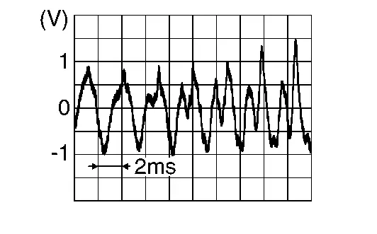
Is the inspection result normal?
YES>>Replace rear door speaker LH. Refer to Removal and Installation.
NO>>Replace Bose speaker amp. Refer to Removal and Installation.
B1a50 Rr-Door Speaker Out
DTC Description
DTC DETECTION LOGIC
| DTC No. |
CONSULT screen terms (Trouble diagnosis content) | DTC detection condition | ||
|---|---|---|---|---|
| B1A50–13 |
RR-DOOR speaker OUT (Rear door speaker RH) |
[OPEN] | Diagnosis condition | Ignition switch ON. |
| Signal (terminal) |
|
|||
| Threshold | — | |||
| Diagnosis delay time | 30 seconds or more | |||
| B1A50–1A | [SHORT] | Diagnosis condition | Ignition switch ON. | |
| Signal (terminal) |
|
|||
| Threshold | — | |||
| Diagnosis delay time | 30 seconds or more | |||
| B1A50–11 | [GND–SHORT] | Diagnosis condition | Ignition switch ON. | |
| Signal (terminal) |
|
|||
| Threshold | — | |||
| Diagnosis delay time | 30 seconds or more | |||
| B1A50–12 | [VB–SHOR] | Diagnosis condition | Ignition switch ON. | |
| Signal (terminal) |
|
|||
| Threshold | — | |||
| Diagnosis delay time | 30 seconds or more | |||
POSSIBLE CAUSE
-
RR DR RH+ open, short, short to ground, short to voltage
-
RR DR RH− open, short, short to ground, short to voltage
-
Rear door speaker RH
-
Bose speaker amp.
FAIL-SAFE
Rear door speaker RH inoperative
Confirmation Procedure
PERFORM DTC CONFIRMATION PROCEDURE
 CONSULT
-
Ignition switch ON.
-
Ignition switch OFF and wait for 4 minutes.
-
Ignition switch ON and wait at least 1 minute or more.
-
Select “Self Diagnostic Result” mode of “Audio amp.”.
-
Check DTC.
Is DTC B1A50 detected?
YES>>Proceed to Diagnosis Procedure.
NO>>To check malfunction symptom before repair: Refer to Intermittent Incident.
NO>>Confirmation after repair: Inspection End.
Diagnosis Procedure
DETERMINE MALFUNCTION TYPE
 CONSULT
-
Ignition switch ON.
-
Ignition switch OFF and wait for 4 minutes.
-
Ignition switch ON and wait at least 1 minute or more.
-
Select “Self Diagnostic Result” mode of “Audio amp.”.
-
Check DTC.
Is DTC B1A50–11, 12, 13 or 1A detected?
YES>>13 [OPEN], or 11 [GND–SHORT] – GO TO 2.
YES>>1A [SHORT] – GO TO 3.
YES>>12 [VB–SHOR] – GO TO 4.
NO>>Refer to Intermittent Incident.
CHECK SOUND SIGNAL CIRCUITS FOR OPEN OR SHORT TO GROUND
-
Ignition switch OFF.
-
Disconnect Bose speaker amp. connector B130 and rear door speaker RH connector.
-
Check the continuity between Bose speaker amp. connector B130 and rear door speaker RH connector D306.
Bose speaker amp. Rear door speaker RH Continuity Connector Terminal Connector Terminal B130 42 D306 1 Yes 49 2 -
Check the continuity between Bose speaker amp. connector B130 and ground.
Bose speaker amp. Continuity Connector Terminal Ground B130 42 — No 49
Is the inspection result normal?
YES>>GO TO 5.
NO>>Repair or replace harness or connectors.
CHECK SOUND SIGNAL CIRCUITS FOR SHORT
-
Ignition switch OFF.
-
Disconnect Bose speaker amp. connector B130 and rear door speaker RH connector.
-
Check the continuity between the terminals of Bose speaker amp. connector B130.
Bose speaker amp. Continuity Connector Terminal B130 42 49 No
Is the inspection result normal?
YES>>GO TO 5.
NO>>Repair or replace harness or connectors.
CHECK SOUND SIGNAL CIRCUIT FOR SHORT TO POWER SUPPLY
-
Ignition switch OFF.
-
Disconnect Bose speaker amp. connector B130 and rear door speaker RH connector.
-
Ignition switch ON.
-
Check the voltage between Bose speaker amp. connector B130 and ground.
Bose speaker amp. Ground Voltage
Approx.Connector Terminal B130 42 — 0 V 49
Is the inspection result normal?
YES>>GO TO 5.
NO>>Repair or replace harness or connectors.
CHECK REAR DOOR SPEAKER RH SIGNAL
-
Connect Bose speaker amp. connector B130 and rear door speaker RH connector.
-
Ignition switch ON.
-
Push AV control unit POWER switch.
-
Check signal between the terminals of Bose speaker amp. connector B130.
Bose speaker amp. Condition Reference value Connector (+) (−) Terminal Terminal B130 42 49 Audio signal output 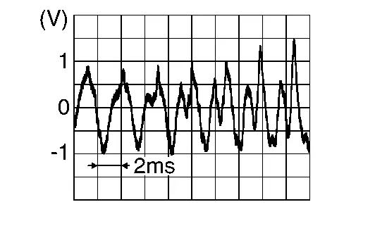
Is the inspection result normal?
YES>>Replace rear door speaker RH. Refer to Removal and Installation.
NO>>Replace Bose speaker amp. Refer to Removal and Installation.
B1a62 Rl-Pillar Squawker Out
DTC Description
DTC DETECTION LOGIC
| DTC No. |
CONSULT screen terms (Trouble diagnosis content) | DTC detection condition | ||
|---|---|---|---|---|
| B1A62–13 |
RL-PLLAR squawker OUT (Rear side speaker LH) |
[OPEN] | Diagnosis condition | Ignition switch ON. |
| Signal (terminal) |
|
|||
| Threshold | — | |||
| Diagnosis delay time | 30 seconds or more | |||
| B1A62–1A | [SHORT] | Diagnosis condition | Ignition switch ON. | |
| Signal (terminal) |
|
|||
| Threshold | — | |||
| Diagnosis delay time | 30 seconds or more | |||
| B1A62–11 | [GND–SHORT] | Diagnosis condition | Ignition switch ON. | |
| Signal (terminal) |
|
|||
| Threshold | — | |||
| Diagnosis delay time | 30 seconds or more | |||
| B1A62–12 | [VB–SHOR] | Diagnosis condition | Ignition switch ON. | |
| Signal (terminal) |
|
|||
| Threshold | — | |||
| Diagnosis delay time | 30 seconds or more | |||
POSSIBLE CAUSE
-
RR SUR LH+ open, short, short to ground, short to voltage
-
RR SUR LH− open, short, short to ground, short to voltage
-
Rear side speaker LH
-
Bose speaker amp.
FAIL-SAFE
Rear side speaker LH inoperative
Confirmation Procedure
PERFORM DTC CONFIRMATION PROCEDURE
 CONSULT
-
Ignition switch ON.
-
Ignition switch OFF and wait for 4 minutes.
-
Ignition switch ON and wait at least 1 minute or more.
-
Select “Self Diagnostic Result” mode of “Audio amp.”.
-
Check DTC.
Is DTC B1A62 detected?
YES>>Proceed to DTC Diagnosis Procedure.
NO>>To check malfunction symptom before repair: Refer to Intermittent Incident.
NO>>Confirmation after repair: Inspection End.
DTC Diagnosis Procedure
DETERMINE MALFUNCTION TYPE
 CONSULT
-
Ignition switch ON.
-
Ignition switch OFF and wait for 4 minutes.
-
Ignition switch ON and wait at least 1 minute or more.
-
Select “Self Diagnostic Result” mode of “Audio amp.”.
-
Check DTC.
Is DTC B1A62–11, 12, 13 or 1A detected?
YES>>13 [OPEN], or 11 [GND–SHORT] – GO TO 2.
YES>>1A [SHORT] – GO TO 3.
YES>>12 [VB–SHOR] – GO TO 4.
NO>>Refer to Intermittent Incident.
CHECK SOUND SIGNAL CIRCUITS FOR OPEN OR SHORT TO GROUND
-
Ignition switch OFF.
-
Disconnect Bose speaker amp. connector B130 and rear side speaker LH connector.
-
Check the continuity between Bose speaker amp. connector B130 and rear side speaker LH connector B1.
Bose speaker amp. Rear side speaker LH Continuity Connector Terminal Connector Terminal B130 44 B1 1 Yes 53 2 -
Check the continuity between Bose speaker amp. connector B130 and ground.
Bose speaker amp. Continuity Connector Terminal Ground B130 44 — No 53
Is the inspection result normal?
YES>>GO TO 5.
NO>>Repair or replace harness or connectors.
CHECK SOUND SIGNAL CIRCUITS FOR SHORT
-
Ignition switch OFF.
-
Disconnect Bose speaker amp. connector B130 and rear side speaker LH connector.
-
Check the continuity between the terminals of Bose speaker amp. connector B130.
Bose speaker amp. Continuity Connector Terminal B130 44 53 No
Is the inspection result normal?
YES>>GO TO 5.
NO>>Repair or replace harness or connectors.
CHECK SOUND SIGNAL CIRCUIT FOR SHORT TO POWER SUPPLY
-
Ignition switch OFF.
-
Disconnect Bose speaker amp. connector B130 and rear side speaker LH connector.
-
Ignition switch ON.
-
Check the voltage between Bose speaker amp. connector B130 and ground.
Bose speaker amp. Ground Voltage
Approx.Connector Terminal B130 44 — 0 V 53
Is the inspection result normal?
YES>>GO TO 5.
NO>>Repair or replace harness or connectors.
CHECK REAR SIDE SPEAKER LH SIGNAL
-
Connect Bose speaker amp. connector B130 and rear side speaker LH connector.
-
Ignition switch ON.
-
Push AV control unit POWER switch.
-
Check signal between the terminals of Bose speaker amp. connector B130.
Bose speaker amp. Condition Reference value Connector (+) (−) Terminal Terminal B130 44 53 Audio signal output 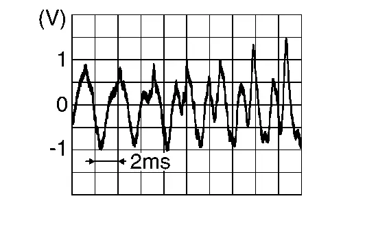
Is the inspection result normal?
YES>>Replace rear side speaker LH. Refer to Removal and Installation.
NO>>Replace Bose speaker amp. Refer to Removal and Installation.
B1a66 Rr-Pillar Squawker Out
DTC Description
DTC DETECTION LOGIC
| DTC No. |
CONSULT screen terms (Trouble diagnosis content) | DTC detection condition | ||
|---|---|---|---|---|
| B1A66–13 |
RR-PLLAR squawker OUT (Rear side speaker RH) |
[OPEN] | Diagnosis condition | Ignition switch ON. |
| Signal (terminal) |
|
|||
| Threshold | — | |||
| Diagnosis delay time | 30 seconds or more | |||
| B1A66–1A | [SHORT] | Diagnosis condition | Ignition switch ON. | |
| Signal (terminal) |
|
|||
| Threshold | — | |||
| Diagnosis delay time | 30 seconds or more | |||
| B1A66–11 | [GND–SHORT] | Diagnosis condition | Ignition switch ON. | |
| Signal (terminal) |
|
|||
| Threshold | — | |||
| Diagnosis delay time | 30 seconds or more | |||
| B1A66–12 | [VB–SHOR] | Diagnosis condition | Ignition switch ON. | |
| Signal (terminal) |
|
|||
| Threshold | — | |||
| Diagnosis delay time | 30 seconds or more | |||
POSSIBLE CAUSE
-
RR SUR RH+ open, short, short to ground, short to voltage
-
RR SUR RH− open, short, short to ground, short to voltage
-
Rear side speaker RH
-
Bose speaker amp.
FAIL-SAFE
Rear side speaker RH inoperative
Confirmation Procedure
PERFORM DTC CONFIRMATION PROCEDURE
 CONSULT
-
Ignition switch ON.
-
Ignition switch OFF and wait for 4 minutes.
-
Ignition switch ON and wait at least 1 minute or more.
-
Select “Self Diagnostic Result” mode of “Audio amp.”.
-
Check DTC.
Is DTC B1A66 detected?
YES>>Proceed to DTC Diagnosis Procedure.
NO>>To check malfunction symptom before repair: Refer to Intermittent Incident.
NO>>Confirmation after repair: Inspection End.
DTC Diagnosis Procedure
DETERMINE MALFUNCTION TYPE
 CONSULT
-
Ignition switch ON.
-
Ignition switch OFF and wait for 4 minutes.
-
Ignition switch ON and wait at least 1 minute or more.
-
Select “Self Diagnostic Result” mode of “Audio amp.”.
-
Check DTC.
Is DTC B1A66–11, 12, 13 or 1A detected?
YES>>13 [OPEN], or 11 [GND–SHORT] – GO TO 2.
YES>>1A [SHORT] – GO TO 3.
YES>>12 [VB–SHOR] – GO TO 4.
NO>>Refer to Intermittent Incident.
CHECK SOUND SIGNAL CIRCUITS FOR OPEN OR SHORT TO GROUND
-
Ignition switch OFF.
-
Disconnect Bose speaker amp. connector B130 and rear side speaker RH connector.
-
Check the continuity between Bose speaker amp. connector B130 and rear side speaker RH connector B153.
Bose speaker amp. Rear side speaker RH Continuity Connector Terminal Connector Terminal B130 45 B153 1 Yes 54 2 -
Check the continuity between Bose speaker amp. connector B130 and ground.
Bose speaker amp. Continuity Connector Terminal (–) B130 45 Ground No 54
Is the inspection result normal?
YES>>GO TO 5.
NO>>Repair or replace harness or connectors.
CHECK SOUND SIGNAL CIRCUITS FOR SHORT
-
Ignition switch OFF.
-
Disconnect Bose speaker amp. connector B130 and rear side speaker RH connector.
-
Check the continuity between the terminals of Bose speaker amp. connector B130.
Bose speaker amp. Continuity Connector Terminal B130 45 54 No
Is the inspection result normal?
YES>>GO TO 5.
NO>>Repair or replace harness or connectors.
CHECK SOUND SIGNAL CIRCUIT FOR SHORT TO POWER SUPPLY
-
Ignition switch OFF.
-
Disconnect Bose speaker amp. connector B130 and rear side speaker RH connector.
-
Ignition switch ON.
-
Check the voltage between Bose speaker amp. connector B130 and ground.
Bose speaker amp. (–) Voltage
Approx.Connector Terminal B130 45 Ground 0 V 54
Is the inspection result normal?
YES>>GO TO 5.
NO>>Repair or replace harness or connectors.
CHECK REAR SIDE SPEAKER RH SIGNAL
-
Connect Bose speaker amp. connector B130 and rear side speaker RH connector.
-
Ignition switch ON.
-
Push AV control unit POWER switch.
-
Check signal between the terminals of Bose speaker amp. connector B130.
Bose speaker amp. Condition Reference value Connector (+) (−) Terminal Terminal B130 45 54 Audio signal output 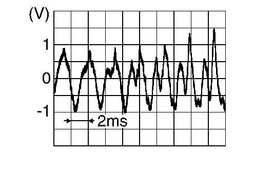
Is the inspection result normal?
YES>>Replace rear side speaker RH. Refer to Removal and Installation.
NO>>Replace Bose speaker amp. Refer to Removal and Installation.
B1a69 Rear Luggage Left Woofer Out
DTC Description
DTC DETECTION LOGIC
| DTC No. |
CONSULT screen terms (Trouble diagnosis content) | DTC detection condition | ||
|---|---|---|---|---|
| B1A69–13 |
Rear luggage left woofer out (Subwoofer) |
[OPEN] | Diagnosis condition | Ignition switch ON. |
| Signal (terminal) |
|
|||
| Threshold | — | |||
| Diagnosis delay time | 30 seconds or more | |||
| B1A69–1A | [SHORT] | Diagnosis condition | Ignition switch ON. | |
| Signal (terminal) |
|
|||
| Threshold | — | |||
| Diagnosis delay time | 30 seconds or more | |||
| B1A69–11 | [GND–SHORT] | Diagnosis condition | Ignition switch ON. | |
| Signal (terminal) |
|
|||
| Threshold | — | |||
| Diagnosis delay time | 30 seconds or more | |||
| B1A69–12 | [VB–SHOR] | Diagnosis condition | Ignition switch ON. | |
| Signal (terminal) |
|
|||
| Threshold | — | |||
| Diagnosis delay time | 30 seconds or more | |||
POSSIBLE CAUSE
-
BASS BOX1+ open, short, short to ground, short to voltage
-
BASS BOX1− open, short, short to ground, short to voltage
-
Subwoofer
-
Bose speaker amp.
FAIL-SAFE
Subwoofer 1 is inoperative
Confirmation Procedure
PERFORM DTC CONFIRMATION PROCEDURE
 CONSULT
-
Ignition switch ON.
-
Ignition switch OFF and wait for 4 minutes.
-
Ignition switch ON and wait at least 1 minute or more.
-
Select “Self Diagnostic Result” mode of “Audio amp.”.
-
Check DTC.
Is DTC B1A69 detected?
YES>>Proceed to Diagnosis Procedure.
NO>>To check malfunction symptom before repair: Refer to Intermittent Incident.
NO>>Confirmation after repair: Inspection End.
Diagnosis Procedure
DETERMINE MALFUNCTION TYPE
 CONSULT
-
Ignition switch ON.
-
Ignition switch OFF and wait for 4 minutes.
-
Ignition switch ON and wait at least 1 minute or more.
-
Select “Self Diagnostic Result” mode of “Audio amp.”.
-
Check DTC.
Is DTC B1A69–11, 12, 13 or 1A detected?
YES>>13 [OPEN], or 11 [GND–SHORT] – GO TO 2.
YES>>1A [SHORT] – GO TO 3.
YES>>12 [VB–SHOR] – GO TO 4.
NO>>Refer to Intermittent Incident.
CHECK SOUND SIGNAL CIRCUITS FOR OPEN OR SHORT TO GROUND
-
Ignition switch OFF.
-
Disconnect Bose speaker amp. connector B146 and subwoofer connector.
-
Check the continuity between Bose speaker amp. connector B146 and subwoofer connector B73.
Bose speaker amp. Subwoofer Continuity Connector Terminal Connector Terminal B146 68 B73 1 Yes 61 2 -
Check the continuity between Bose speaker amp. connector B146 and ground.
Bose speaker amp. Continuity Connector Terminal Ground B146 68 — No 61
Is the inspection result normal?
YES>>GO TO 5.
NO>>Repair or replace harness or connectors.
CHECK SOUND SIGNAL CIRCUITS FOR SHORT
-
Ignition switch OFF.
-
Disconnect Bose speaker amp. connector B146 and subwoofer connector.
-
Check the continuity between the terminals of Bose speaker amp. connector B146.
Bose speaker amp. Continuity Connector Terminal B146 68 61 No
Is the inspection result normal?
YES>>GO TO 5.
NO>>Repair or replace harness or connectors.
CHECK SOUND SIGNAL CIRCUIT FOR SHORT TO POWER SUPPLY
-
Ignition switch OFF.
-
Disconnect Bose speaker amp. connector B146 and subwoofer connector.
-
Ignition switch ON.
-
Check the voltage between Bose speaker amp. connector B146 and ground.
Bose speaker amp. Ground Voltage
Approx.Connector Terminal B146 68 — 0 V 61
Is the inspection result normal?
YES>>GO TO 5.
NO>>Repair or replace harness or connectors.
CHECK REAR SIDE SPEAKER LH SIGNAL
-
Connect Bose speaker amp. connector B146 and subwoofer connector.
-
Ignition switch ON.
-
Push AV control unit POWER switch.
-
Check signal between the terminals of Bose speaker amp. connector B146.
Bose speaker amp. Condition Reference value Connector (+) (−) Terminal Terminal B146 68 61 Audio signal output 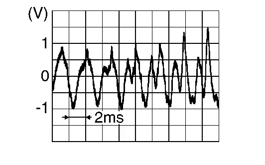
Is the inspection result normal?
YES>>Replace subwoofer. Refer to Removal and Installation.
NO>>Replace Bose speaker amp. Refer to Removal and Installation.
B1a71 Rear Luggage Right Woofer Out
DTC Description
DTC DETECTION LOGIC
| DTC No. |
CONSULT screen terms (Trouble diagnosis content) | DTC detection condition | ||
|---|---|---|---|---|
| B1A71–13 |
Rear luggage right woofer out (Subwoofer) |
[OPEN] | Diagnosis condition | Ignition switch ON. |
| Signal (terminal) |
|
|||
| Threshold | — | |||
| Diagnosis delay time | 30 seconds or more | |||
| B1A71–1A | [SHORT] | Diagnosis condition | Ignition switch ON. | |
| Signal (terminal) |
|
|||
| Threshold | — | |||
| Diagnosis delay time | 30 seconds or more | |||
| B1A71–11 | [GND–SHORT] | Diagnosis condition | Ignition switch ON. | |
| Signal (terminal) |
|
|||
| Threshold | — | |||
| Diagnosis delay time | 30 seconds or more | |||
| B1A71–12 | [VB–SHOR] | Diagnosis condition | Ignition switch ON. | |
| Signal (terminal) |
|
|||
| Threshold | — | |||
| Diagnosis delay time | 30 seconds or more | |||
POSSIBLE CAUSE
-
BASS BOX2+ open, short, short to ground, short to voltage
-
BASS BOX2− open, short, short to ground, short to voltage
-
Subwoofer
-
Bose speaker amp.
FAIL-SAFE
Subwoofer 2 is inoperative
Confirmation Procedure
PERFORM DTC CONFIRMATION PROCEDURE
 CONSULT
-
Ignition switch ON.
-
Ignition switch OFF and wait for 4 minutes.
-
Ignition switch ON and wait at least 1 minute or more.
-
Select “Self Diagnostic Result” mode of “Audio amp.”.
-
Check DTC.
Is DTC B1A71 detected?
YES>>Proceed to Diagnosis Procedure.
NO>>To check malfunction symptom before repair: Refer to Intermittent Incident.
NO>>Confirmation after repair: Inspection End.
Diagnosis Procedure
DETERMINE MALFUNCTION TYPE
 CONSULT
-
Ignition switch ON.
-
Ignition switch OFF and wait for 4 minutes.
-
Ignition switch ON and wait at least 1 minute or more.
-
Select “Self Diagnostic Result” mode of “Audio amp.”.
-
Check DTC.
Is DTC B1A71–11, 12, 13 or 1A detected?
YES>>13 [OPEN], or 11 [GND–SHORT] – GO TO 2.
YES>>1A [SHORT] – GO TO 3.
YES>>12 [VB–SHOR] – GO TO 4.
NO>>Refer to Intermittent Incident.
CHECK SOUND SIGNAL CIRCUITS FOR OPEN OR SHORT TO GROUND
-
Ignition switch OFF.
-
Disconnect Bose speaker amp. connector B147 and subwoofer connector.
-
Check the continuity between Bose speaker amp. connector B147 and subwoofer connector B73.
Bose speaker amp. Subwoofer Continuity Connector Terminal Connector Terminal B147 73 B73 3 Yes 69 4 -
Check the continuity between Bose speaker amp. connector B147 and ground.
Bose speaker amp. Continuity Connector Terminal Ground B147 73 — No 69
Is the inspection result normal?
YES>>GO TO 5.
NO>>Repair or replace harness or connectors.
CHECK SOUND SIGNAL CIRCUITS FOR SHORT
-
Ignition switch OFF.
-
Disconnect Bose speaker amp. connector B147 and subwoofer connector.
-
Check the continuity between the terminals of Bose speaker amp. connector B147.
Bose speaker amp. Continuity Connector Terminal B147 73 69 No
Is the inspection result normal?
YES>>GO TO 5.
NO>>Repair or replace harness or connectors.
CHECK SOUND SIGNAL CIRCUIT FOR SHORT TO POWER SUPPLY
-
Ignition switch OFF.
-
Disconnect Bose speaker amp. connector B147 and subwoofer connector.
-
Ignition switch ON.
-
Check the voltage between Bose speaker amp. connector B147 and ground.
Bose speaker amp. Ground Voltage
Approx.Connector Terminal B147 73 — 0 V 69
Is the inspection result normal?
YES>>GO TO 5.
NO>>Repair or replace harness or connectors.
CHECK REAR SIDE SPEAKER LH SIGNAL
-
Connect Bose speaker amp. connector B147 and subwoofer connector.
-
Ignition switch ON.
-
Push AV control unit POWER switch.
-
Check signal between the terminals of Bose speaker amp. connector B147.
Bose speaker amp. Condition Reference value Connector (+) (−) Terminal Terminal B147 73 69 Audio signal output 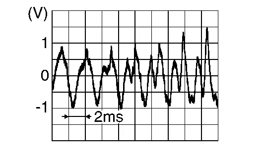
Is the inspection result normal?
YES>>Replace subwoofer. Refer to Removal and Installation.
NO>>Replace Bose speaker amp. Refer to Removal and Installation.
B1a80 Anc Unit
DTC Description
DTC DETECTION LOGIC
| DTC No. |
CONSULT screen terms (Trouble diagnosis content) | DTC detection condition | |
|---|---|---|---|
| B1A80-49 |
ANC UNIT (Bose speaker amp.) |
Diagnosis condition | Ignition switch ON |
| Signal (terminal) | — | ||
| Threshold | Bose speaker amp. malfunction | ||
| Diagnosis delay time | 30 seconds or more | ||
| B1A80-4B | Diagnosis condition | Ignition switch ON | |
| Signal (terminal) | — | ||
| Threshold | Bose speaker amp. temperature above 124 ℃ (255 ℉) | ||
| Diagnosis delay time | 1 second or more | ||
| B1A80-55 | Diagnosis condition | Ignition switch ON | |
| Signal (terminal) | — | ||
| Threshold | Bose speaker amp. configuration is incomplete | ||
| Diagnosis delay time | 30 seconds or more | ||
POSSIBLE CAUSE
-
Bose speaker amp. malfunction
-
Bose speaker amp. temperature is high
-
Bose speaker amp. configuration is incomplete
-
Bose speaker amp.
FAIL-SAFE
Bose speaker amp. is inoperative.
Confirmation Procedure
PERFORM DTC CONFIRMATION PROCEDURE
 CONSULT
-
Ignition switch ON.
-
Ignition switch OFF and wait for 4 minutes.
-
Ignition switch ON and wait at least 1 minute or more.
-
Select “Self Diagnostic Result” mode of “Audio amp.”.
-
Check DTC.
Is DTC B1A80 detected?
YES>>Proceed to Diagnosis Procedure.
NO>>To check malfunction symptom before repair: Refer to Intermittent Incident.
NO>>Confirmation after repair: Inspection End.
Diagnosis Procedure
DETERMINE MALFUNCTION TYPE
 CONSULT
-
Ignition switch ON.
-
Ignition switch OFF and wait 4 minutess.
-
Ignition switch ON and wait at least 1 minute more.
-
Select “Self Diagnostic Result” mode of “Audio amp.”.
-
Check DTC.
Is DTC B1A80–49, 4B or 55 detected?
YES>>55 – GO TO 2.
YES>>4B – GO TO 3.
YES>>49 – GO TO 4.
NO>>Refer to Intermittent Incident.
PERFORM CONFIGURATION PROCEDURE
Perform configuration of Bose speaker amp. Refer to Work Procedure.
>>
GO TO 4.
CHECK BOSE SPEAKER AMP.
Visually check around Bose speaker amp. for a cause of high temperature.
Is the inspection result normal?
YES>>GO TO 4.
NO>>Remove cause of high temperature.
PERFORM DTC CONFIRMATION PROCEDURE
 CONSULT
-
Ignition switch ON.
-
Ignition switch OFF and wait for 4 minutes.
-
Ignition switch ON and wait at least 1 minute or more.
-
Select “Self Diagnostic Result” mode of “Audio amp.”.
-
Check DTC.
Is DTC B1A80–49, 4B or 55 detected?
YES>>Replace Bose speaker amp. Refer to Removal and Installation.
NO>>Inspection End.
U0079 Control Module Comm Bus G Off
DTC Description
DTC DETECTION LOGIC
| DTC No. |
CONSULT screen terms (Trouble diagnosis content) | DTC detection condition | ||
|---|---|---|---|---|
| U0079–00 |
Control module comm bus G off (Control module communication Bus G Off) |
[—] | Diagnosis condition | When ignition switch is ON. |
| Signal (terminal) | CAN communication signal | |||
| Threshold | Transmit or receive is abnormal | |||
| Diagnosis delay time | 2 seconds or more | |||
POSSIBLE CAUSE
CAN communication system
FAIL-SAFE
CAN communication does not function.
Confirmation Procedure
PERFORM DTC CONFIRMATION PROCEDURE
 CONSULT
-
Ignition switch ON.
-
Ignition switch OFF and wait for 4 minutes.
-
Ignition switch ON and wait at least 1 minute or more.
-
Select “Self Diagnostic Result” mode of “Audio amp.”.
-
Check DTC.
Is DTC U0079–00 detected?
YES>>Proceed to DTC Diagnosis Procedure.
NO>>To check malfunction symptom before repair: Refer to Intermittent Incident.
NO>>Confirmation after repair: Inspection End.
DTC Diagnosis Procedure
PERFORM DTC CONFIRMATION PROCEDURE AGAIN
 CONSULT
-
Ignition switch ON.
-
Erase DTC.
-
Perform DTC confirmation procedure again. Refer to Confirmation Procedure.
Is DTC detected again?
YES>>Perform the trouble diagnosis for CAN communication system. Refer to Trouble Diagnosis Flow Chart.
NO>>Inspection End.
U2140 Can Comm Err (ecm)
DTC Description
DTC DETECTION LOGIC
| DTC No. |
CONSULT screen terms (Trouble diagnosis content) | DTC detection condition | |
|---|---|---|---|
| U2140–87 |
CAN comm err (ECM) (CAN communication signals) |
Diagnosis condition | When ignition switch is ON. |
| Signal (terminal) | CAN communication signals | ||
| Threshold | When CAN signals cannot be received continuously for more than 2 seconds | ||
| Diagnosis delay time | 2 seconds or more | ||
POSSIBLE CAUSE
-
CAN communication signals
-
Bose speaker amp.
FAIL-SAFE
All self-diagnosis functions are inoperative
Confirmation Procedure
PERFORM DTC CONFIRMATION PROCEDURE
 CONSULT
-
Ignition switch ON.
-
Ignition switch OFF and wait for 4 minutes.
-
Ignition switch ON and wait at least 1 minute or more.
-
Select “Self Diagnostic Result” mode of “Audio amp.”.
-
Check DTC.
Is DTC U2140–87 detected?
YES>>Proceed to DTC Diagnosis Procedure.
NO>>To check malfunction symptom before repair: Refer to Intermittent Incident.
NO>>Confirmation after repair: Inspection End.
DTC Diagnosis Procedure
PERFORM DTC CONFIRMATION PROCEDURE
 CONSULT
-
Ignition switch ON.
-
Ignition switch OFF and wait for 4 minutes.
-
Ignition switch ON and wait at least 1 minute or more.
-
Select “Self Diagnostic Result” mode of “Audio amp.”.
-
Check DTC.
Is DTC U2140–87 detected?
YES>>Replace Bose speaker amp. Refer to Removal and Installation.
NO>>Inspection End.
U2148 Can Comm Err (brake Control Unit)
DTC Description
DTC DETECTION LOGIC
| DTC No. |
CONSULT screen terms (Trouble diagnosis content) | DTC detection condition | |
|---|---|---|---|
| U2148–87 |
CAN comm err (brake control unit) (CAN communication signals) |
Diagnosis condition | When ignition switch is ON. |
| Signal (terminal) | CAN communication signals | ||
| Threshold | When CAN signals cannot be received continuously for more than 2 seconds | ||
| Diagnosis delay time | 2 seconds or more | ||
POSSIBLE CAUSE
-
CAN communication signals
-
Bose speaker amp.
FAIL-SAFE
All self-diagnosis functions are inoperative
Confirmation Procedure
PERFORM DTC CONFIRMATION PROCEDURE
 CONSULT
-
Ignition switch ON.
-
Ignition switch OFF and wait for 4 minutes.
-
Ignition switch ON and wait at least 1 minute or more.
-
Select “Self Diagnostic Result” mode of “Audio amp.”.
-
Check DTC.
Is DTC U2148–87 detected?
YES>>Proceed to DTC Diagnosis Procedure.
NO>>To check malfunction symptom before repair: Refer to Intermittent Incident.
NO>>Confirmation after repair: Inspection End.
DTC Diagnosis Procedure
PERFORM DTC CONFIRMATION PROCEDURE
 CONSULT
-
Ignition switch ON.
-
Ignition switch OFF and wait for 4 minutes.
-
Ignition switch ON and wait at least 1 minute or more.
-
Select “Self Diagnostic Result” mode of “Audio amp.”.
-
Check DTC.
Is DTC U2148–87 detected?
YES>>Replace Bose speaker amp. Refer to Removal and Installation.
NO>>Inspection End.
U214e Can Comm Err (combination Meter)
DTC Description
DTC DETECTION LOGIC
| DTC No. |
CONSULT screen terms (Trouble diagnosis content) | DTC detection condition | |
|---|---|---|---|
| U214E–87 |
CAN comm err (combination meter) (CAN communication signals) |
Diagnosis condition | When ignition switch is ON. |
| Signal (terminal) | CAN communication signals | ||
| Threshold | When CAN signals cannot be received continuously for more than 2 seconds | ||
| Diagnosis delay time | 2 seconds or more | ||
POSSIBLE CAUSE
-
CAN communication signals
-
Bose speaker amp.
FAIL-SAFE
All self-diagnosis functions are inoperative
Confirmation Procedure
PERFORM DTC CONFIRMATION PROCEDURE
 CONSULT
-
Ignition switch ON.
-
Ignition switch OFF and wait for 4 minutes.
-
Ignition switch ON and wait at least 1 minute or more.
-
Select “Self Diagnostic Result” mode of “Audio amp.”.
-
Check DTC.
Is DTC U214E–87 detected?
YES>>Proceed to DTC Diagnosis Procedure.
NO>>To check malfunction symptom before repair: Refer to Intermittent Incident.
NO>>Confirmation after repair: Inspection End.
DTC Diagnosis Procedure
PERFORM DTC CONFIRMATION PROCEDURE
 CONSULT
-
Ignition switch ON.
-
Ignition switch OFF and wait for 4 minutes.
-
Ignition switch ON and wait at least 1 minute or more.
-
Select “Self Diagnostic Result” mode of “Audio amp.”.
-
Check DTC.
Is DTC U214E–87 detected?
YES>>Replace Bose speaker amp. Refer to Removal and Installation.
NO>>Inspection End.
U214f Can Comm Err (bcm)
DTC Description
DTC DETECTION LOGIC
| DTC No. |
CONSULT screen terms (Trouble diagnosis content) | DTC detection condition | |
|---|---|---|---|
| U214F–87 |
CAN comm err (BCM) (CAN communication signals) |
Diagnosis condition | When ignition switch is ON. |
| Signal (terminal) | CAN communication signals | ||
| Threshold | When CAN signals cannot be received continuously for more than 2 seconds | ||
| Diagnosis delay time | 2 seconds or more | ||
POSSIBLE CAUSE
-
CAN communication signals
-
Bose speaker amp.
FAIL-SAFE
All self-diagnosis functions are inoperative
Confirmation Procedure
PERFORM DTC CONFIRMATION PROCEDURE
 CONSULT
-
Ignition switch ON.
-
Ignition switch OFF and wait for 4 minutes.
-
Ignition switch ON and wait at least 1 minute or more.
-
Select “Self Diagnostic Result” mode of “Audio amp.”.
-
Check DTC.
Is DTC U214F–87 detected?
YES>>Proceed to DTC Diagnosis Procedure.
NO>>To check malfunction symptom before repair: Refer to Intermittent Incident.
NO>>Confirmation after repair: Inspection End.
DTC Diagnosis Procedure
PERFORM DTC CONFIRMATION PROCEDURE
 CONSULT
-
Ignition switch ON.
-
Ignition switch OFF and wait for 4 minutes.
-
Ignition switch ON and wait at least 1 minute or more.
-
Select “Self Diagnostic Result” mode of “Audio amp.”.
-
Check DTC.
Is DTC U214F–87 detected?
YES>>Replace Bose speaker amp. Refer to Removal and Installation.
NO>>Inspection End.
U215b Can Comm Err (ipdm E/r)
DTC Description
DTC DETECTION LOGIC
| DTC No. |
CONSULT screen terms (Trouble diagnosis content) | DTC detection condition | |
|---|---|---|---|
| U215B–87 |
CAN comm err (IPDM E/R) (CAN communication signals) |
Diagnosis condition | When ignition switch is ON. |
| Signal (terminal) | CAN communication signals | ||
| Threshold | When CAN signals cannot be received continuously for more than 2 seconds | ||
| Diagnosis delay time | 2 seconds or more | ||
POSSIBLE CAUSE
CAN communication signals
FAIL-SAFE
All self-diagnosis functions are inoperative
Confirmation Procedure
PERFORM DTC CONFIRMATION PROCEDURE
 CONSULT
-
Ignition switch ON.
-
Ignition switch OFF and wait for 4 minutes.
-
Ignition switch ON and wait at least 1 minute or more.
-
Select “Self Diagnostic Result” mode of “Audio amp.”.
-
Check DTC.
Is DTC U215B–87 detected?
YES>>Proceed to Diagnosis Procedure.
NO>>To check malfunction symptom before repair: Refer to Intermittent Incident.
NO>>Confirmation after repair: Inspection End.
Diagnosis Procedure
PERFORM DTC CONFIRMATION PROCEDURE AGAIN
 CONSULT
-
Ignition switch ON.
-
Erase DTC.
-
Perform DTC confirmation procedure again. Refer to Confirmation Procedure.
Is DTC U215B–87 detected?
YES>>Perform the trouble diagnosis for CAN communication system. Refer to Trouble Diagnosis Flow Chart.
NO>>Inspection End.
Power Supply and Ground Circuit
Diagnosis Procedure
CHECK FUSE
Check that the following fuses are not blown:
| Terminal No. | Signal name | Fuse No. | Capacity |
|---|---|---|---|
| 57 | Battery power supply | 28 | (20A) |
| 58 | |||
| 59 | 27 | (10A) |
Are the fuses blown?
YES>>Replace the blown fuse after repairing the affected circuit.
NO>>GO TO 2.
CHECK POWER SUPPLY CIRCUIT
-
Ignition switch OFF.
-
Disconnect Bose speaker amp. connector.
-
Check voltage between Bose speaker amp. connector and ground.
Bose speaker amp. Ground Condition Voltage
(Approx.)Connector Terminal B146 57 — Ignition switch: OFF Battery voltage 58 59
Is the inspection result normal?
YES>>GO TO 3.
NO>>Repair or replace harness or connectors.
CHECK GROUND CIRCUIT
Check continuity between Bose speaker amp. connector and ground.
| Bose speaker amp. | Ground | Continuity | |
|---|---|---|---|
| Connector | Terminal | ||
| B146 | 62 | — | Yes |
| 63 | |||
| 64 | |||
Is the inspection result normal?
YES>>Inspection End.
NO>>Repair or replace harness or connectors.

Nissan Pathfinder (R53) 2022-2026 Service Manual
Dtc/circuit Diagnosis
Contact Us
Nissan Pathfinder Info Center
Email: info@nipathfinder.com
Phone: +1 (800) 123-4567
Address: 123 Pathfinder Blvd, Nashville, TN 37214, USA
Working Hours: Mon–Fri, 9:00 AM – 5:00 PM (EST)
