Nissan Pathfinder: Dtc/circuit Diagnosis - Multi Av (av Control Unit) ++
B1305 Control Unit Internal Fault
DTC Description
DTC DETECTION LOGIC
| DTC No. |
CONSULT screen terms (Trouble diagnosis content) |
DTC detection condition | ||
|---|---|---|---|---|
| B1305–04 |
Control unit internal fault (AV control unit internal fault) |
[—] | Diagnosis condition | When ignition switch is ON. |
| Signal (terminal) | – | |||
| Threshold | Internal fault | |||
| Diagnosis delay time | 30 seconds or more | |||
POSSIBLE CAUSE
AV control unit internal fault
FAIL-SAFE
AV control unit internal error
Confirmation Procedure
PERFORM DTC CONFIRMATION PROCEDURE
 CONSULT
-
Ignition switch ON.
-
Ignition switch OFF and wait at least 30 seconds.
-
Ignition switch ON and wait at least 30 seconds or more.
-
Select “Self Diagnostic Result” mode of “MULTI AV”.
-
Check DTC.
Is DTC B1305–04 detected?
YES>>
Proceed to DTC Diagnosis Procedure.
NO>>
To check malfunction symptom before repair: Refer to Intermittent Incident.
NO>>
Confirmation after repair: Inspection End.
DTC Diagnosis Procedure
PERFORM DTC CONFIRMATION PROCEDURE
 CONSULT
-
Ignition switch ON.
-
Ignition switch OFF and wait at least 30 seconds.
-
Ignition switch ON and wait at least 30 seconds or more.
-
Select “Self Diagnostic Result” mode of “MULTI AV”.
-
Check DTC.
Is DTC B1305–04 detected?
YES>>
Replace AV control unit. Refer to Removal and Installation.
NO>>
Inspection End.
B1309 Av Control Unit
DTC Description
DTC DETECTION LOGIC
| DTC No. |
CONSULT screen terms (Trouble diagnosis content) |
DTC detection condition | ||
|---|---|---|---|---|
| B1309–11 |
AV control unit (Amplifier ON circuit) |
[GND–SHOR] | Diagnosis condition | When ignition switch is ON. |
| Signal (terminal) | — | |||
| Threshold | — | |||
| Diagnosis delay time | 30 seconds or more | |||
| B1309–12 | [VB–SHOR] | Diagnosis condition | When ignition switch is ON. | |
| Signal (terminal) | — | |||
| Threshold | — | |||
| Diagnosis delay time | 30 seconds or more | |||
POSSIBLE CAUSE
AV control unit
FAIL-SAFE
No sound from Bose speaker amp.
Confirmation Procedure
PERFORM DTC CONFIRMATION PROCEDURE
 CONSULT
-
Ignition switch ON.
-
Ignition switch OFF and wait at least 30 seconds.
-
Ignition switch ON and wait at least 30 seconds or more.
-
Select “Self Diagnostic Result” mode of “MULTI AV”.
-
Check DTC.
Is DTC B1309 detected?
YES>>
Proceed to DTC Diagnosis Procedure.
NO>>
To check malfunction symptom before repair: Refer to Intermittent Incident.
NO>>
Confirmation after repair: Inspection End.
DTC Diagnosis Procedure
PERFORM DTC CONFIRMATION PROCEDURE
 CONSULT
-
Ignition switch ON.
-
Ignition switch OFF and wait at least 30 seconds.
-
Ignition switch ON and wait at least 30 seconds or more.
-
Select “Self Diagnostic Result” mode of “MULTI AV”.
-
Check DTC.
Is DTC B1309 detected?
YES>>
Replace AV control unit. Refer to Removal and Installation.
NO>>
Inspection End.
B130b Rear Rh Speaker
DTC Description
DTC DETECTION LOGIC
| DTC No. |
CONSULT screen terms (Trouble diagnosis content) |
DTC detection condition | ||
|---|---|---|---|---|
| B130B–13 |
Rear RH speaker (Rear door speaker RH) |
[OPEN] | Diagnosis condition | When ignition switch is ON. |
| Signal (terminal) |
|
|||
| Threshold | – | |||
| Diagnosis delay time | 30 seconds or more | |||
| B130B–1C | [SHORT] | Diagnosis condition | When ignition switch is ON. | |
| Signal (terminal) |
|
|||
| Threshold | – | |||
| Diagnosis delay time | 30 seconds or more | |||
| B130B–11 | [GND–SHORT] | Diagnosis condition | When ignition switch is ON. | |
| Signal (terminal) |
|
|||
| Threshold | – | |||
| Diagnosis delay time | 30 seconds or more | |||
| B130B–12 | [VB–SHOR] | Diagnosis condition | When ignition switch is ON. | |
| Signal (terminal) |
|
|||
| Threshold | – | |||
| Diagnosis delay time | 30 seconds or more | |||
POSSIBLE CAUSE
-
RR SP RH+ open, short, short to ground, short to voltage
-
RR SP RH− open, short, short to ground, short to voltage
-
Rear door speaker RH
-
AV control unit
FAIL-SAFE
Rear door speaker RH inoperative
DTC Confirmation Procedure
PERFORM DTC CONFIRMATION PROCEDURE
 CONSULT
-
Ignition switch ON.
-
Ignition switch OFF and wait at least 30 seconds.
-
Ignition switch ON and wait at least 30 seconds or more.
-
Select “Self Diagnostic Result” mode of “MULTI AV”.
-
Check DTC.
Is DTC B130B detected?
YES>>
Proceed to Diagnosis Procedure.
NO>>
To check malfunction symptom before repair: Refer to Intermittent Incident.
NO>>
Confirmation after repair: Inspection End.
Diagnosis Procedure
DETERMINE MALFUNCTION TYPE
 CONSULT
-
Ignition switch ON.
-
Ignition switch OFF and wait at least 30 seconds.
-
Ignition switch ON and wait at least 30 seconds or more.
-
Select “Self Diagnostic Result” mode of “MULTI AV”.
-
Check DTC.
Is DTC B130B–11, 12, 13 or 1C detected?
YES>>
13 [OPEN], or 11 [GND–SHORT] – GO TO 2.
YES>>
1C [SHORT] – GO TO 3.
YES>>
12 [VB–SHOR] – GO TO 4.
NO>>
Refer to Intermittent Incident.
CHECK SOUND SIGNAL CIRCUITS FOR OPEN OR SHORT TO GROUND
-
Ignition switch OFF.
-
Disconnect AV control unit connector M121 and rear door speaker RH connector.
-
Check the continuity between AV control unit connector M121 and rear door speaker RH connector D306.
AV control unit Rear door speaker RH Continuity Connector Terminal Connector Terminal M121 13 D306 1 Yes 14 2 -
Check the continuity between AV control unit connector M121 and ground.
AV control unit Continuity Connector Terminal Ground M121 13 — No 14
Is the inspection result normal?
YES>>
GO TO 5.
NO>>
Repair or replace harness or connectors.
CHECK SOUND SIGNAL CIRCUITS FOR SHORT
-
Ignition switch OFF.
-
Disconnect AV control unit connector M121 and rear door speaker RH connector.
-
Check the continuity between the terminals of AV control unit connector M121.
AV control unit Continuity Connector Terminal M121 13 14 No
Is the inspection result normal?
YES>>
GO TO 5.
NO>>
Repair or replace harness or connectors.
CHECK SOUND SIGNAL CIRCUIT FOR SHORT TO POWER SUPPLY
-
Ignition switch OFF.
-
Disconnect AV control unit connector M121 and rear door speaker RH connector.
-
Ignition switch ON.
-
Check the voltage between AV control unit connector M121 and ground.
AV control unit Ground Voltage
Approx.Connector Terminal M121 13 — 0 V 14
Is the inspection result normal?
YES>>
GO TO 5.
NO>>
Repair or replace harness or connectors.
CHECK REAR RH SPEAKER SIGNAL
-
Connect AV control unit connector M121 and rear door speaker RH connector.
-
Ignition switch ON.
-
Push AV control unit POWER switch.
-
Check signal between the terminals of AV control unit connector M121.
AV control unit connector M121 Condition Reference value (+) (−) Terminal Terminal 13 14 Audio signal output 
Is the inspection result normal?
YES>>
Replace rear door speaker RH. Refer to Removal and Installation.
NO>>
Replace AV control unit. Refer to Removal and Installation.
B130d Front Rh Speaker
DTC Description
DTC DETECTION LOGIC
| DTC No. |
CONSULT screen terms (Trouble diagnosis content) |
DTC detection condition | ||
|---|---|---|---|---|
| B130D–13 |
Front RH speaker (Front door speaker RH and instrument panel tweeter RH) |
[OPEN] | Diagnosis condition | When ignition switch is ON. |
| Signal (terminal) |
|
|||
| Threshold | – | |||
| Diagnosis delay time | 30 seconds or more | |||
| B130D–1C | [SHORT] | Diagnosis condition | When ignition switch is ON. | |
| Signal (terminal) |
|
|||
| Threshold | – | |||
| Diagnosis delay time | 30 seconds or more | |||
| B130D–11 | [GND–SHORT] | Diagnosis condition | When ignition switch is ON. | |
| Signal (terminal) |
|
|||
| Threshold | – | |||
| Diagnosis delay time | 30 seconds or more | |||
| B130D–12 | [VB–SHOR] | Diagnosis condition | When ignition switch is ON. | |
| Signal (terminal) |
|
|||
| Threshold | – | |||
| Diagnosis delay time | 30 seconds or more | |||
POSSIBLE CAUSE
-
FR SP RH+ open, short, short to ground, short to voltage
-
FR SP RH− open, short, short to ground, short to voltage
-
Front door speaker RH
-
Instrument panel tweeter RH
-
AV control unit
FAIL-SAFE
-
Failure type byte 11, 12 and 1C:
-
Front door speaker RH inoperative
-
Instrument panel tweeter RH inoperative
-
-
Failure type byte 13: front door speaker RH inoperative
Confirmation Procedure
PERFORM DTC CONFIRMATION PROCEDURE
 CONSULT
-
Ignition switch ON.
-
Ignition switch OFF and wait at least 30 seconds.
-
Ignition switch ON and wait at least 30 seconds or more.
-
Select “Self Diagnostic Result” mode of “MULTI AV”.
-
Check DTC.
Is DTC B130D detected?
YES>>
Proceed to Diagnosis Procedure.
NO>>
To check malfunction symptom before repair: Refer to Intermittent Incident.
NO>>
Confirmation after repair: Inspection End.
Diagnosis Procedure
DETERMINE MALFUNCTION TYPE
 CONSULT
-
Ignition switch ON.
-
Ignition switch OFF and wait at least 30 seconds.
-
Ignition switch ON and wait at least 30 seconds or more.
-
Select “Self Diagnostic Result” mode of “MULTI AV”.
-
Check DTC.
Is DTC B130D–11, 12, 13 or 1C detected?
YES>>
13 [OPEN], or 11 [GND–SHORT] – GO TO 2.
YES>>
1C [SHORT] – GO TO 3.
YES>>
12 [VB–SHOR] – GO TO 4.
NO>>
Refer to Intermittent Incident.
CHECK SOUND SIGNAL CIRCUITS FOR OPEN OR SHORT TO GROUND
-
Ignition switch OFF.
-
Disconnect AV control unit connector M121, front door speaker RH connector and instrument panel tweeter RH connector.
-
Check the continuity between AV control unit connector M121 and front door speaker RH connector D112.
AV control unit Front door speaker RH Continuity Connector Terminal Connector Terminal M121 11 D112 1 Yes 12 2 -
Check the continuity between AV control unit connector M121 and ground.
AV control unit Continuity Connector Terminal Ground M121 11 — No 12
Is the inspection result normal?
YES>>
GO TO 5.
NO>>
Repair or replace harness or connectors.
CHECK SOUND SIGNAL CIRCUITS FOR SHORT
-
Ignition switch OFF.
-
Disconnect AV control unit connector M121, front door speaker RH connector and instrument panel tweeter RH connector.
-
Check the continuity between the terminals of AV control unit connector M121.
AV control unit Continuity Connector Terminal M121 11 12 No
Is the inspection result normal?
YES>>
GO TO 5.
NO>>
Repair or replace harness or connectors.
CHECK SOUND SIGNAL CIRCUIT FOR SHORT TO POWER SUPPLY
-
Ignition switch OFF.
-
Disconnect AV control unit connector M121, front door speaker RH connector and instrument panel tweeter RH connector.
-
Ignition switch ON.
-
Check the voltage between AV control unit connector M121 and ground.
AV control unit Ground Voltage
Approx.Connector Terminal M121 11 — 0 V 12
Is the inspection result normal?
YES>>
GO TO 5.
NO>>
Repair or replace harness or connectors.
CHECK FRONT RH SPEAKER SIGNAL
-
Connect AV control unit connector M121, front door speaker RH connector and instrument panel tweeter RH connector.
-
Ignition switch ON.
-
Push AV control unit POWER switch.
-
Check signal between the terminals of AV control unit connector M121.
AV control unit connector M121 Condition Reference value (+) (−) Terminal Terminal 11 12 Audio signal output 
Is the inspection result normal?
YES>>
Replace front door speaker RH or instrument panel tweeter RH. Refer to Removal and Installation (front door speaker) or Removal and Installation (instrument panel tweeter).
NO>>
Replace AV control unit. Refer to Removal and Installation.
B130f Front Lh Speaker
DTC Description
DTC DETECTION LOGIC
| DTC No. |
CONSULT screen terms (Trouble diagnosis content) |
DTC detection condition | ||
|---|---|---|---|---|
| B130F–13 |
Front LH speaker (Front door speaker LH and instrument panel tweeter LH) |
[OPEN] | Diagnosis condition | When ignition switch is ON. |
| Signal (terminal) |
|
|||
| Threshold | – | |||
| Diagnosis delay time | 30 seconds or more | |||
| B130F–1C | [SHORT] | Diagnosis condition | When ignition switch is ON. | |
| Signal (terminal) |
|
|||
| Threshold | – | |||
| Diagnosis delay time | 30 seconds or more | |||
| B130F–11 | [GND–SHORT] | Diagnosis condition | When ignition switch is ON. | |
| Signal (terminal) |
|
|||
| Threshold | – | |||
| Diagnosis delay time | 30 seconds or more | |||
| B130F–12 | [VB–SHOR] | Diagnosis condition | When ignition switch is ON. | |
| Signal (terminal) |
|
|||
| Threshold | – | |||
| Diagnosis delay time | 30 seconds or more | |||
POSSIBLE CAUSE
-
FR SP LH+ open, short, short to ground, short to voltage
-
FR SP LH− open, short, short to ground, short to voltage
-
Front door speaker LH
-
Instrument panel tweeter LH
-
AV control unit
FAIL-SAFE
-
Failure type byte 11, 12 and 1C:
-
Front door speaker LH inoperative
-
Instrument panel tweeter LH inoperative
-
-
Failure type byte 13: front door speaker LH inoperative
DTC Confirmation Procedure
PERFORM DTC CONFIRMATION PROCEDURE
 CONSULT
-
Ignition switch ON.
-
Ignition switch OFF and wait at least 30 seconds.
-
Ignition switch ON and wait at least 30 seconds or more.
-
Select “Self Diagnostic Result” mode of “MULTI AV”.
-
Check DTC.
Is DTC B130F detected?
YES>>
Proceed to Diagnosis Procedure.
NO>>
To check malfunction symptom before repair: Refer to Intermittent Incident.
NO>>
Confirmation after repair: Inspection End.
Diagnosis Procedure
DETERMINE MALFUNCTION TYPE
 CONSULT
-
Ignition switch ON.
-
Ignition switch OFF and wait at least 30 seconds.
-
Ignition switch ON and wait at least 30 seconds or more.
-
Select “Self Diagnostic Result” mode of “MULTI AV”.
-
Check DTC.
Is DTC B130F–11, 12, 13 or 1C detected?
YES>>
13 [OPEN], or 11 [GND–SHORT] – GO TO 2.
YES>>
1C [SHORT] – GO TO 3.
YES>>
12 [VB–SHOR] – GO TO 4.
NO>>
Refer to Intermittent Incident.
CHECK SOUND SIGNAL CIRCUITS FOR OPEN OR SHORT TO GROUND
-
Ignition switch OFF.
-
Disconnect AV control unit connector M121, front door speaker LH connector and instrument panel tweeter LH connector D12.
-
Check the continuity between AV control unit connector M121 and front door speaker LH connector D12.
AV control unit Front door speaker LH Continuity Connector Terminal Connector Terminal M121 2 D12 1 Yes 3 2 -
Check the continuity between AV control unit connector M121 and ground.
AV control unit Continuity Connector Terminal Ground M121 2 — No 3
Is the inspection result normal?
YES>>
GO TO 5.
NO>>
Repair or replace harness or connectors.
CHECK SOUND SIGNAL CIRCUITS FOR SHORT
-
Ignition switch OFF.
-
Disconnect AV control unit connector M121, front door speaker LH connector and instrument panel tweeter LH connector.
-
Check the continuity between the terminals of AV control unit connector M121.
AV control unit Continuity Connector Terminal M121 2 3 No
Is the inspection result normal?
YES>>
GO TO 5.
NO>>
Repair or replace harness or connectors.
CHECK SOUND SIGNAL CIRCUIT FOR SHORT TO POWER SUPPLY
-
Ignition switch OFF.
-
Disconnect AV control unit connector M121, front door speaker LH connector and instrument panel tweeter LH connector.
-
Ignition switch ON.
-
Check the voltage between AV control unit connector M121 and ground.
AV control unit Ground Voltage
Approx.Connector Terminal M121 2 — 0 V 3
Is the inspection result normal?
YES>>
GO TO 5.
NO>>
Repair or replace harness or connectors.
CHECK FRONT LH SPEAKER SIGNAL
-
Connect AV control unit connector M121, front door speaker LH connector and instrument panel tweeter LH connector.
-
Ignition switch ON.
-
Push AV control unit POWER switch.
-
Check signal between the terminals of AV control unit connector M121.
AV control unit connector M121 Condition Reference value (+) (−) Terminal Terminal 2 3 Audio signal output 
Is the inspection result normal?
YES>>
Replace front door speaker LH or instrument panel tweeter LH. Refer to Removal and Installation (front door speaker) or Removal and Installation (instrument panel tweeter).
NO>>
Replace AV control unit. Refer to Removal and Installation.
B1311 Rear Lh Speaker
DTC Description
DTC DETECTION LOGIC
| DTC No. |
CONSULT screen terms (Trouble diagnosis content) |
DTC detection condition | ||
|---|---|---|---|---|
| B1311–13 |
Rear LH speaker (Rear door speaker LH) |
[OPEN] | Diagnosis condition | When ignition switch is ON. |
| Signal (terminal) |
|
|||
| Threshold | – | |||
| Diagnosis delay time | 30 seconds or more | |||
| B1311–1C | [SHORT] | Diagnosis condition | When ignition switch is ON. | |
| Signal (terminal) |
|
|||
| Threshold | – | |||
| Diagnosis delay time | 30 seconds or more | |||
| B1311–11 | [GND–SHORT] | Diagnosis condition | When ignition switch is ON. | |
| Signal (terminal) |
|
|||
| Threshold | – | |||
| Diagnosis delay time | 30 seconds or more | |||
| B1311–12 | [VB–SHOR] | Diagnosis condition | When ignition switch is ON. | |
| Signal (terminal) |
|
|||
| Threshold | – | |||
| Diagnosis delay time | 30 seconds or more | |||
POSSIBLE CAUSE
-
RR SP LH+ open, short, short to ground, short to voltage
-
RR SP LH− open, short, short to ground, short to voltage
-
Rear door speaker LH
-
AV control unit
FAIL-SAFE
Rear door speaker LH inoperative
DTC Confirmation Procedure
PERFORM DTC CONFIRMATION PROCEDURE
 CONSULT
-
Ignition switch ON.
-
Ignition switch OFF and wait at least 30 seconds.
-
Ignition switch ON and wait at least 30 seconds or more.
-
Select “Self Diagnostic Result” mode of “MULTI AV”.
-
Check DTC.
Is DTC B1311 detected?
YES>>
Proceed to Diagnosis Procedure.
NO>>
To check malfunction symptom before repair: Refer to Intermittent Incident.
NO>>
Confirmation after repair: Inspection End.
Diagnosis Procedure
DETERMINE MALFUNCTION TYPE
 CONSULT
-
Ignition switch ON.
-
Ignition switch OFF and wait at least 30 seconds.
-
Ignition switch ON and wait at least 30 seconds or more.
-
Select “Self Diagnostic Result” mode of “MULTI AV”.
-
Check DTC.
Is DTC B1311–11, 12, 13 or 1C detected?
YES>>
13 [OPEN], or 11 [GND–SHORT] – GO TO 2.
YES>>
1C [SHORT] – GO TO 3.
YES>>
12 [VB–SHOR] – GO TO 4.
NO>>
Refer to Intermittent Incident.
CHECK SOUND SIGNAL CIRCUITS FOR OPEN OR SHORT TO GROUND
-
Ignition switch OFF.
-
Disconnect AV control unit connector M121 and rear door speaker LH connector.
-
Check the continuity between AV control unit connector M121 and rear door speaker LH connector D206.
AV control unit Rear door speaker LH Continuity Connector Terminal Connector Terminal M121 4 D206 1 Yes 5 2 -
Check the continuity between AV control unit connector M121 and ground.
AV control unit Continuity Connector Terminal Ground M121 4 — No 5
Is the inspection result normal?
YES>>
GO TO 5.
NO>>
Repair or replace harness or connectors.
CHECK SOUND SIGNAL CIRCUITS FOR SHORT
-
Ignition switch OFF.
-
Disconnect AV control unit connector M121 and rear door speaker LH connector.
-
Check the continuity between the terminals of AV control unit connector M121.
AV control unit Continuity Connector Terminal M121 4 5 No
Is the inspection result normal?
YES>>
GO TO 5.
NO>>
Repair or replace harness or connectors.
CHECK SOUND SIGNAL CIRCUIT FOR SHORT TO POWER SUPPLY
-
Ignition switch OFF.
-
Disconnect AV control unit connector M121 and rear door speaker LH connector.
-
Ignition switch ON.
-
Check the voltage between AV control unit connector M121 and ground.
AV control unit Ground Voltage
Approx.Connector Terminal M121 4 — 0 V 5
Is the inspection result normal?
YES>>
GO TO 5.
NO>>
Repair or replace harness or connectors.
CHECK REAR LH SPEAKER SIGNAL
-
Connect AV control unit connector M121 and rear door speaker LH connector.
-
Ignition switch ON.
-
Push AV control unit POWER switch.
-
Check signal between the terminals of AV control unit connector M121.
AV control unit connector M121 Condition Reference value (+) (−) Terminal Terminal 4 5 Audio signal output 
Is the inspection result normal?
YES>>
Replace rear door speaker LH. Refer to Removal and Installation.
NO>>
Replace AV control unit. Refer to Removal and Installation.
B1315 Am/fm 1 Antenna
DTC Description
DTC DETECTION LOGIC
| DTC No. |
CONSULT screen terms (Trouble diagnosis content) |
DTC detection condition | ||
|---|---|---|---|---|
| B1315–13 |
AM/FM 1 antenna (Radio antenna) |
[OPEN] | Diagnosis condition | When ignition switch is ON. |
| Signal (terminal) | AM-FM main circuit between AV control unit and antenna base (terminal 83) | |||
| Threshold | – | |||
| Diagnosis delay time | 30 seconds or more | |||
| B1315–11 | [GND–SHORT] | Diagnosis condition | When ignition switch is ON. | |
| Signal (terminal) | AM-FM main circuit between AV control unit and antenna base (terminal 83) | |||
| Threshold | – | |||
| Diagnosis delay time | 30 seconds or more | |||
POSSIBLE CAUSE
-
Radio antenna is not connected
-
Harness or connector (AM-FM main circuit is open or short to ground)
FAIL-SAFE
No AM/FM radio reception
DTC Confirmation Procedure
PERFORM DTC CONFIRMATION PROCEDURE
 CONSULT
-
Ignition switch ON.
-
Ignition switch OFF and wait at least 30 seconds.
-
Ignition switch ON and wait at least 30 seconds or more.
-
Select “Self Diagnostic Result” mode of “MULTI AV”.
-
Check DTC.
Is DTC B1315 detected?
YES>>
Proceed to Diagnosis Procedure.
NO>>
To check malfunction symptom before repair: Refer to Intermittent Incident.
NO>>
Confirmation after repair: Inspection End.
Diagnosis Procedure
CHECK ANTENNA CONNECTOR
-
Ignition switch OFF.
-
Visually inspect antenna base, antenna feeder and antenna connectors.
Is the inspection result normal?
YES>>
GO TO 2.
NO>>
Repair or replace malfunctioning parts.
CHECK ANTENNA CIRCUIT CONTINUITY
-
Ignition switch OFF.
-
Disconnect AV control unit connector M155 and antenna base connector.
-
Check continuity between AV control unit connector M155 and antenna base connector.
AV control unit Antenna base Continuity Connector Terminal Connector Terminal M155 83 R203 (without satellite radio)
R204 (with satellite radio)1 Yes -
Check continuity between AV control unit connector M155 and ground.
AV control unit Ground Continuity Connector Terminal M155 83 — No
Is the inspection result normal?
YES>>
Replace antenna base. Refer to Refer to Removal and Installation..
NO>>
Replace AV control unit. Refer to Removal and Installation.
B1316 Fm 2 Antenna
DTC Description
DTC DETECTION LOGIC
| DTC No. |
CONSULT screen terms (Trouble diagnosis content) |
DTC detection condition | ||
|---|---|---|---|---|
| B1316–13 |
FM 2 antenna [Glass antenna (FM sub)] |
[OPEN] | Diagnosis condition | When ignition switch is ON. |
| Signal (terminal) | FM SUB circuit (terminal 89) | |||
| Threshold | – | |||
| Diagnosis delay time | 30 seconds or more | |||
| B1316–11 | [GND–SHORT] | Diagnosis condition | When ignition switch is ON. | |
| Signal (terminal) | FM SUB circuit (terminal 89) | |||
| Threshold | – | |||
| Diagnosis delay time | 30 seconds or more | |||
POSSIBLE CAUSE
-
Glass antenna (FM SUB) is not connected
-
Harness or connector (FM SUB circuit is open or short to ground)
FAIL-SAFE
No FM radio reception
Confirmation Procedure
PERFORM DTC CONFIRMATION PROCEDURE
 CONSULT
-
Ignition switch ON.
-
Ignition switch OFF and wait at least 30 seconds.
-
Ignition switch ON and wait at least 30 seconds or more.
-
Select “Self Diagnostic Result” mode of “MULTI AV”.
-
Check DTC.
Is DTC B1316 detected?
YES>>
Proceed to DTC Diagnosis Procedure.
NO>>
To check malfunction symptom before repair: Refer to Intermittent Incident.
NO>>
Confirmation after repair: Inspection End.
DTC Diagnosis Procedure
CHECK ANTENNA CONNECTOR
-
Ignition switch OFF.
-
Visually inspect glass antenna (FM SUB), antenna feeder and antenna connectors.
Is the inspection result normal?
YES>>
GO TO 2.
NO>>
Repair or replace malfunctioning parts.
CHECK ANTENNA CIRCUIT CONTINUITY
-
Ignition switch OFF.
-
Disconnect AV control unit connector M152 and glass antenna (FM SUB) connector D601.
-
Check continuity between AV control unit connector M152 and glass antenna (FM SUB) connector D601.
AV control unit Glass antenna (FM SUB) Continuity Connector Terminal Connector Terminal M152 89 D601 1 Yes -
Check continuity between AV control unit connector M152 and ground.
AV control unit Ground Continuity Connector Terminal M152 89 — No
Is the inspection result normal?
YES>>
Replace back door window glass. Refer to Removal and Installation.
NO>>
Replace AV control unit. Refer to Removal and Installation.
B1317 Xm Antenna Connection
DTC Description
DTC DETECTION LOGIC
| DTC No. |
CONSULT screen terms (Trouble diagnosis content) |
DTC detection condition | ||
|---|---|---|---|---|
| B1317–13 |
XM antenna connection (Satellite antenna connection) |
[OPEN] | Diagnosis condition | When ignition switch is ON. |
| Signal (terminal) | Satellite antenna signal between AV control unit and satellite antenna (terminal 85) | |||
| Threshold | – | |||
| Diagnosis delay time | 30 seconds or more | |||
| B1317–11 | [GND–SHORT] | Diagnosis condition | When ignition switch is ON. | |
| Signal (terminal) | Satellite antenna signal between AV control unit and satellite antenna (terminal 85) | |||
| Threshold | – | |||
| Diagnosis delay time | 30 seconds or more | |||
POSSIBLE CAUSE
-
Satellite antenna is not connected
-
Harness or connector (Satellite antenna circuit is open or short to ground)
FAIL-SAFE
No satellite radio reception
Confirmation Procedure
PERFORM DTC CONFIRMATION PROCEDURE
 CONSULT
-
Ignition switch ON.
-
Ignition switch OFF and wait at least 30 seconds.
-
Ignition switch ON and wait at least 30 seconds or more.
-
Select “Self Diagnostic Result” mode of “MULTI AV”.
-
Check DTC.
Is DTC B1317 detected?
YES>>
Proceed to DTC Diagnosis Procedure.
NO>>
To check malfunction symptom before repair: Refer to Intermittent Incident.
NO>>
Confirmation after repair: Inspection End.
DTC Diagnosis Procedure
CHECK SATELLITE RADIO ANTENNA CONNECTOR
-
Ignition switch OFF.
-
Visually inspect antenna base, antenna feeder and antenna connectors.
Is the inspection result normal?
YES>>
GO TO 2.
NO>>
Repair or replace malfunctioning parts.
CHECK SATELLITE RADIO ANTENNA CIRCUIT CONTINUITY
-
Ignition switch OFF.
-
Disconnect AV control unit connector M156 and antenna base connector.
-
Check continuity between AV control unit connector M156 and antenna base connector.
AV control unit Antenna base Continuity Connector Terminal Connector Terminal M156 85 R204 3 Yes -
Check continuity between AV control unit connector M156 and ground.
AV control unit Ground Continuity Connector Terminal M156 85 — No
Is the inspection result normal?
YES>>
Replace antenna base. Refer to Removal and Installation.
NO>>
Replace AV control unit. Refer to Removal and Installation.
B1321 Front Rh Tweeter
DTC Description
DTC DETECTION LOGIC
| DTC No. |
CONSULT screen terms (Trouble diagnosis content) |
DTC detection condition | ||
|---|---|---|---|---|
| B1321–13 |
Front RH tweeter (Instrument panel tweeter RH) |
[OPEN] | Diagnosis condition | When ignition switch is ON. |
| Signal (terminal) |
|
|||
| Threshold | – | |||
| Diagnosis delay time | 30 seconds or more | |||
POSSIBLE CAUSE
-
FR SP RH+ open
-
FR SP RH− open
-
Instrument panel tweeter RH
-
AV control unit
FAIL-SAFE
Instrument panel tweeter RH inoperative
Confirmation Procedure
PERFORM DTC CONFIRMATION PROCEDURE
 CONSULT
-
Ignition switch ON.
-
Ignition switch OFF and wait at least 30 seconds.
-
Ignition switch ON and wait at least 30 seconds or more.
-
Select “Self Diagnostic Result” mode of “MULTI AV”.
-
Check DTC.
Is DTC B1321–13 detected?
YES>>
Proceed to DTC Diagnosis Procedure.
NO>>
To check malfunction symptom before repair: Refer to Intermittent Incident.
NO>>
Confirmation after repair: Inspection End.
DTC Diagnosis Procedure
CHECK SOUND SIGNAL CIRCUITS FOR OPEN
-
Ignition switch OFF.
-
Disconnect AV control unit connector M121 and instrument panel tweeter RH connector.
-
Check the continuity between AV control unit connector M103 and instrument panel tweeter RH connector M73.
AV control unit Instrument panel tweeter RH Continuity Connector Terminal Connector Terminal M121 11 M73 1 Yes 12 2
Is the inspection result normal?
YES>>
GO TO 2.
NO>>
Repair or replace harness or connectors.
CHECK INSTRUMENT PANEL TWEETER RH SIGNAL
-
Connect AV control unit connector M121 and instrument panel tweeter RH connector.
-
Ignition switch ON.
-
AV control unit ON.
-
Check signal between the terminals of AV control unit connector M121.
AV control unit Condition Reference value Connector (+) (−) Terminal M121 11 12 Audio signal output 
Is the inspection result normal?
YES>>
Replace instrument panel tweeter RH. Refer to Removal and Installation.
NO>>
Replace AV control unit. Refer to Removal and Installation.
B1322 Front Lh Tweeter
DTC Description
DTC DETECTION LOGIC
| DTC No. |
CONSULT screen terms (Trouble diagnosis content) |
DTC detection condition | ||
|---|---|---|---|---|
| B1322–13 |
Front LH tweeter (Instrument panel tweeter LH) |
[OPEN] | Diagnosis condition | When ignition switch is ON. |
| Signal (terminal) |
|
|||
| Threshold | – | |||
| Diagnosis delay time | 30 seconds or more | |||
POSSIBLE CAUSE
-
FR SP LH+ open
-
FR SP LH− open
-
Instrument panel tweeter LH
-
AV control unit
FAIL-SAFE
Instrument panel tweeter LH inoperative
Confirmation Procedure
PERFORM DTC CONFIRMATION PROCEDURE
 CONSULT
-
Ignition switch ON.
-
Ignition switch OFF and wait at least 30 seconds.
-
Ignition switch ON and wait at least 30 seconds or more.
-
Select “Self Diagnostic Result” mode of “MULTI AV”.
-
Check DTC.
Is DTC B1322–13 detected?
YES>>
Proceed to DTC Diagnosis Procedure.
NO>>
To check malfunction symptom before repair: Refer to Intermittent Incident.
NO>>
Confirmation after repair: Inspection End.
DTC Diagnosis Procedure
CHECK SOUND SIGNAL CIRCUITS FOR OPEN
-
Ignition switch OFF.
-
Disconnect AV control unit connector M121 and instrument panel tweeter LH connector.
-
Check the continuity between AV control unit connector M121 and instrument panel tweeter LH connector M62.
AV control unit Instrument panel tweeter LH Continuity Connector Terminal Connector Terminal M121 2 M62 1 Yes 3 2
Is the inspection result normal?
YES>>
GO TO 2.
NO>>
Repair or replace harness or connectors.
CHECK INSTRUMENT PANEL TWEETER LH SIGNAL
-
Connect AV control unit connector M121 and front instrument panel tweeter LH connector.
-
Ignition switch ON.
-
AV control unit ON.
-
Check signal between the terminals of AV control unit connector M121.
AV control unit Condition Reference value Connector (+) (−) Terminal M121 2 3 Audio signal output 
Is the inspection result normal?
YES>>
Replace instrument panel tweeter LH. Refer to Removal and Installation.
NO>>
Replace AV control unit. Refer to Removal and Installation.
B1328 External Microphone 1
DTC Description
DTC DETECTION LOGIC
| DTC No. |
CONSULT screen terms (Trouble diagnosis content) |
DTC detection condition | ||
|---|---|---|---|---|
| B1328–13 |
External microphone 1 (Microphone) |
[OPEN or GND-SHORT] | Diagnosis condition | When ignition switch is ON. |
| Signal (terminal) | — | |||
| Threshold | – | |||
| Diagnosis delay time | 30 seconds or more | |||
| B1328–12 | [VB–SHOR] | Diagnosis condition | When ignition switch is ON. | |
| Signal (terminal) | — | |||
| Threshold | – | |||
| Diagnosis delay time | 30 seconds or more | |||
POSSIBLE CAUSE
-
Harness or connector
-
AV control unit
-
Microphone
FAIL-SAFE
Microphone is inoperative
Confirmation Procedure
PERFORM DTC CONFIRMATION PROCEDURE
 CONSULT
-
Ignition switch ON.
-
Ignition switch OFF and wait at least 30 seconds.
-
Ignition switch ON and wait at least 30 seconds or more.
-
Select “Self Diagnostic Result” mode of “MULTI AV”.
-
Check DTC.
Is DTC B1328 detected?
YES>>
Proceed to DTC Diagnosis Procedure.
NO>>
To check malfunction symptom before repair: Refer to Intermittent Incident.
NO>>
Confirmation after repair: Inspection End.
DTC Diagnosis Procedure
DETERMINE MALFUNCTION TYPE
 CONSULT
-
Ignition switch ON.
-
Ignition switch OFF and wait at least 30 seconds.
-
Ignition switch ON and wait at least 30 seconds or more.
-
Select “Self Diagnostic Result” mode of “MULTI AV”.
-
Check DTC.
Is DTC B1328–12 or 13 detected?
YES>>
13 [OPEN] or [GND–SHORT] – GO TO 2.
YES>>
12 [VB–SHOR] – GO TO 3.
NO>>
Refer to Intermittent Incident.
CHECK MICROPHONE CIRCUITS FOR OPEN OR SHORT TO GROUND
-
Ignition switch OFF.
-
Disconnect AV control unit connector and microphone connector.
-
Check the continuity between AV control unit connector and microphone connector.
AV control unit Microphone Continuity Connector Terminal Connector Terminal M123 39 R109 3 Yes 40 8 51 6 59 4 -
Check the continuity between AV control unit connector and ground.
AV control unit Ground Continuity Connector Terminal M123 39 — No 40 51
Is the inspection result normal?
YES>>
GO TO 4.
NO>>
Repair or replace harness or connectors.
CHECK MICROPHONE CIRCUITS FOR SHORT TO POWER SUPPLY
-
Ignition switch ON.
-
Check the voltage between AV control unit connector and ground.
AV control unit Ground Voltage
(Approx.)Connector Terminal M123 39 — 0 V 40 51 59
Is the inspection result normal?
YES>>
GO TO 4.
NO>>
Repair or replace harness or connectors.
CHECK MICROPHONE SIGNAL
Check signal between terminals of AV control unit connector.
| AV control unit | Condition | Reference value | ||
|---|---|---|---|---|
| Connector | (+) | (-) | ||
| Terminals | ||||
| M123 | 40 | 59 | Speak into microphone. |
|
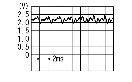
Is the inspection result normal?
YES>>
Replace AV control unit. Refer to Removal and Installation.
NO>>
Replace microphone. Refer to Removal and Installation.
B132a External Usb
DTC Description
DTC DETECTION LOGIC
| DTC No. |
CONSULT screen terms (Trouble diagnosis content) |
DTC detection condition | ||
|---|---|---|---|---|
| B132A–13 |
External USB (USB) |
[OPEN] | Diagnosis condition | When ignition switch is ON. |
| Signal (terminal) | — | |||
| Threshold | – | |||
| Diagnosis delay time | 30 seconds or more | |||
| B132A–01 | [–] | Diagnosis condition | When ignition switch is ON. | |
| Signal (terminal) | — | |||
| Threshold | – | |||
| Diagnosis delay time | 30 seconds or more | |||
| B132A–49 | [–] | Diagnosis condition | When ignition switch is ON. | |
| Signal (terminal) | — | |||
| Threshold | – | |||
| Diagnosis delay time | 30 seconds or more | |||
POSSIBLE CAUSE
-
USB harness is not connected
-
Harness or connector
FAIL-SAFE
USB is inoperative
DTC Confirmation Procedure
PERFORM DTC CONFIRMATION PROCEDURE
 CONSULT
-
Ignition switch ON.
-
Ignition switch OFF and wait at least 30 seconds.
-
Ignition switch ON and wait at least 30 seconds or more.
-
Select “Self Diagnostic Result” mode of “MULTI AV”.
-
Check DTC.
Is DTC B132A detected?
YES>>
Proceed to Diagnosis Procedure.
NO>>
To check malfunction symptom before repair: Refer to Intermittent Incident.
NO>>
Confirmation after repair: Inspection End.
Diagnosis Procedure
DETERMINE MALFUNCTION TYPE
 CONSULT
-
Ignition switch ON.
-
Ignition switch OFF and wait at least 30 seconds.
-
Ignition switch ON and wait at least 30 seconds or more.
-
Select “Self Diagnostic Result” mode of “MULTI AV”.
-
Check DTC.
Is DTC B132A–01, 13 or 49 detected?
YES>>
13 [OPEN] – GO TO 2.
YES>>
01 [–] or 49 [–] – GO TO 3.
NO>>
Refer to Intermittent Incident.
CHECK USB CIRCUITS FOR OPEN
-
Ignition switch OFF.
-
Disconnect AV control unit connector M124 and front auxiliary input jacks connector M166.
-
Check continuity between AV control unit connector M124 and front auxiliary input jacks connector M166.
AV control unit Front auxiliary input jacks Continuity Connector Terminal Connector Terminal M124 61 M166 9 Yes 65 13
Is the inspection result normal?
YES>>
Replace AV control unit. Refer to Removal and Installation.
NO>>
Repair or replace harness or connectors.
PERFORM DTC CONFIRMATION PROCEDURE AGAIN
 CONSULT
-
Ignition switch ON.
-
Erase DTC.
-
Perform DTC confirmation procedure again. Refer to DTC Confirmation Procedure.
Is DTC B132A–01 or B132A–49 detected again?
YES>>
Replace AV control unit. Refer to Removal and Installation.
NO>>
Inspection End.
B132c Tcu Connection
DTC Description
DTC DETECTION LOGIC
| DTC No. |
CONSULT screen terms (Trouble diagnosis content) |
DTC detection condition | ||
|---|---|---|---|---|
| B132C–13 |
TCU connection (TCU USB harness) |
[GND–SHORT] | Diagnosis condition | When ignition switch is ON. |
| Signal (terminal) | — | |||
| Threshold | – | |||
| Diagnosis delay time | 30 seconds or more | |||
| B132C–01 | [–] | Diagnosis condition | When ignition switch is ON. | |
| Signal (terminal) | — | |||
| Threshold | – | |||
| Diagnosis delay time | 30 seconds or more | |||
| B132C–49 | [–] | Diagnosis condition | When ignition switch is ON. | |
| Signal (terminal) | — | |||
| Threshold | – | |||
| Diagnosis delay time | 30 seconds or more | |||
POSSIBLE CAUSE
-
TCU USB harness
-
AV control unit
FAIL-SAFE
Telematics system inoperative
Confirmation Procedure
PERFORM DTC CONFIRMATION PROCEDURE
 CONSULT
-
Ignition switch ON.
-
Ignition switch OFF and wait at least 30 seconds.
-
Ignition switch ON and wait at least 30 seconds or more.
-
Select “Self Diagnostic Result” mode of “MULTI AV”.
-
Check DTC.
Is DTC B132C detected?
YES>>
Proceed to DTC Diagnosis Procedure.
NO>>
To check malfunction symptom before repair: Refer to Intermittent Incident.
NO>>
Confirmation after repair: Inspection End.
DTC Diagnosis Procedure
DETERMINE MALFUNCTION TYPE
 CONSULT
-
Ignition switch ON.
-
Ignition switch OFF and wait at least 30 seconds.
-
Ignition switch ON and wait at least 30 seconds or more.
-
Select “Self Diagnostic Result” mode of “MULTI AV”.
-
Check DTC.
Is DTC B132C–01, 13, or 49 detected?
YES>>
13 [OPEN] – GO TO 2.
YES>>
01 [–] or 49 [–] – GO TO 3.
NO>>
Refer to Intermittent Incident.
CHECK USB CIRCUITS FOR OPEN
-
Ignition switch OFF.
-
Disconnect AV control unit connector and TCU connector.
-
Check continuity between AV control unit connector and TCU connector.
AV control unit TCU Continuity Connector Terminal Connector Terminal M125 (without Bose audio system)
M181 (with Bose audio system)67 M184 41 Yes 71 45
Is the inspection result normal?
YES>>
Replace AV control unit. Refer to Removal and Installation.
NO>>
Repair or replace harness or connectors.
PERFORM DTC CONFIRMATION PROCEDURE AGAIN
 CONSULT
-
Ignition switch ON.
-
Erase DTC.
-
Perform DTC confirmation procedure again. Refer to Confirmation Procedure.
Is DTC B132C–01 or B132C–49 detected again?
YES>>
Replace AV control unit. Refer to Removal and Installation.
NO>>
Inspection End.
B1339 Rear Camera
DTC Description
DTC DETECTION LOGIC
| DTC No. |
CONSULT screen terms (Trouble diagnosis content) |
DTC detection condition | ||
|---|---|---|---|---|
| B1339-8F |
Rear camera (Rear view camera connection) |
[–] | Diagnosis condition | When ignition switch is ON. |
| Signal (terminal) | Camera image signal circuit (terminal 49) | |||
| Threshold | – | |||
| Diagnosis delay time | 30 seconds or more | |||
POSSIBLE CAUSE
-
Camera image signal circuit
-
Rear view camera
-
AV control unit
FAIL-SAFE
Rear view camera is inoperative.
Confirmation Procedure
PERFORM DTC CONFIRMATION PROCEDURE
 CONSULT
-
Ignition switch ON.
-
Ignition switch OFF and wait at least 30 seconds.
-
Ignition switch ON and wait at least 30 seconds or more.
-
Select “Self Diagnostic Result” mode of “MULTI AV”.
-
Check DTC.
Is DTC B1339–8F detected?
YES>>
Proceed to DTC Diagnosis Procedure.
NO>>
To check malfunction symptom before repair: Refer to Intermittent Incident.
NO>>
Confirmation after repair: Inspection End.
DTC Diagnosis Procedure
CHECK CAMERA IMAGE SIGNAL CIRCUIT FOR OPEN
-
Ignition switch OFF.
-
Disconnect AV control unit connector M123 and rear view camera connector.
-
Check the continuity between AV control unit connector M123 and rear view camera connector B462.
AV control unit Rear view camera Continuity Connector Terminal Connector Terminal M123 49 B462 1 Yes
Is the inspection result normal?
YES>>
GO TO 2.
NO>>
Repair harness or connector.
CHECK CAMERA IMAGE SIGNAL CIRCUIT FOR SHORT
Check the continuity between AV control unit connector M123 and ground.
| (+) | (−) | Continuity | |
|---|---|---|---|
| AV control unit | |||
| Connector | Terminal | ||
| M123 | 49 | Ground | No |
Is the inspection result normal?
YES>>
GO TO 3.
NO>>
Repair harness or connector.
CHECK CAMERA IMAGE SIGNAL
-
Connect AV control unit connector M123 and rear view camera connector.
-
Ignition switch ON.
-
Shift the selector lever to “R” position
-
Check the signal between AV control unit connector M123 and ground.
AV control unit ( - ) Condition Reference value ( + ) Connector Terminal M123 49 Ground Camera image is displayed 
Is the inspection result normal?
YES>>
Replace AV control unit. Refer to Removal and Installation.
NO>>
Replace rear view camera. Refer to Removal and Installation.
B133a Around View Monitor
DTC Description
DTC DETECTION LOGIC
| DTC No. |
CONSULT screen terms (Trouble diagnosis content) |
DTC detection condition | |
|---|---|---|---|
| B133A-8F |
Around view monitor (Camera image signal) |
Diagnosis condition | When ignition switch is ON. |
| Signal (terminal) | — | ||
| Threshold | — | ||
| Diagnosis delay time | 30 seconds. | ||
POSSIBLE CAUSE
-
Camera image signal circuit
-
Around view monitor control unit
-
AV control unit
FAIL-SAFE
Camera image is inoperative
Confirmation Procedure
PERFORM DTC CONFIRMATION PROCEDURE
 CONSULT
-
Ignition switch ON.
-
Ignition switch OFF and wait at least 30 seconds.
-
Ignition switch ON and wait at least 30 seconds or more.
-
Select “Self Diagnostic Result” mode of “MULTI AV”.
-
Check DTC.
Is DTC B133A–8F detected?
YES>>
Proceed to DTC Diagnosis Procedure.
NO>>
To check malfunction symptom before repair: Refer to Intermittent Incident.
NO>>
Confirmation after repair: Inspection End.
DTC Diagnosis Procedure
CHECK CAMERA IMAGE SIGNAL CIRCUIT FOR OPEN
-
Ignition switch OFF.
-
Disconnect AV control unit connector and around view monitor control unit connector.
-
Check the continuity between AV control unit connector and around view monitor control unit connector.
AV control unit Around view monitor control unit Continuity Connector Terminal Connector Terminal M144 (without Bose audio system)
M183 (with Bose audio system)81 M106 43 Yes
Is the inspection result normal?
YES>>
GO TO 2.
NO>>
Replace the LVDS harness.
CHECK CAMERA IMAGE SIGNAL CIRCUIT FOR SHORT
Check the continuity between AV control unit connector and ground.
| (+) | (−) | Continuity | |
|---|---|---|---|
| AV control unit | |||
| Connector | Terminal | ||
|
M144 (without Bose audio system) M183 (with Bose audio system) |
81 | Ground | No |
Is the inspection result normal?
YES>>
GO TO 3.
NO>>
Replace the LVDS harness.
CHECK CAMERA IMAGE SIGNAL
-
Connect AV control unit connector and around view monitor control unit connector.
-
Ignition switch ON.
-
Press the “CAMERA” switch.
-
Check the signal between AV control unit connector and ground.
AV control unit ( - ) Condition Reference value ( + ) Connector Terminal M144 (without Bose audio system)
M183 (with Bose audio system)81 Ground Camera image is displayed 
Is the inspection result normal?
YES>>
Replace AV control unit. Refer to Removal and Installation.
NO>>
Replace around view monitor control unit. Refer to Removal and Installation.
B133c Amplifier
DTC Description
DTC DETECTION LOGIC
| DTC No. |
CONSULT screen terms (Trouble diagnosis content) |
DTC detection condition | |
|---|---|---|---|
| B133C–02 |
Amplifier (Bose speaker amp. connection) |
Diagnosis condition | When ignition switch is ON. |
| Signal (terminal) | — | ||
| Threshold | — | ||
| Diagnosis delay time | — | ||
POSSIBLE CAUSE
-
AV communication circuit is open
-
Bose speaker amp.
FAIL-SAFE
Bose speaker amp. is inoperative
Confirmation Procedure
PERFORM DTC CONFIRMATION PROCEDURE
 CONSULT
-
Ignition switch ON.
-
Ignition switch OFF and wait at least 30 seconds.
-
Ignition switch ON and wait at least 30 seconds or more.
-
Select “Self Diagnostic Result” mode of “MULTI AV”.
-
Check DTC.
Is DTC B133C–02 detected?
YES>>
Proceed to DTC Diagnosis Procedure.
NO>>
To check malfunction symptom before repair: Refer to Intermittent Incident.
NO>>
Confirmation after repair: Inspection End.
DTC Diagnosis Procedure
CHECK BOSE SPEAKER AMP. POWER SUPPLY AND GROUND CIRCUIT
Check Bose speaker amp. power supply and ground circuit. Refer to Diagnosis Procedure.
Is the inspection result normal?
YES>>
GO TO 2.
NO>>
Repair or replace malfunctioning parts.
CHECK AV COMMUNICATION CIRCUIT
-
Ignition switch OFF.
-
Disconnect AV control unit connector M160 and Bose speaker amp. connector B129.
-
Check the continuity between AV control unit connector M160 and Bose speaker amp. connector B129.
AV control unit Bose speaker amp. Continuity Connector Terminal Connector Terminal M160 22 B129 14 Yes 23 42 13 43
Is the inspection result normal?
YES>>
Replace Bose speaker amp. Refer to Removal and Installation.
NO>>
Repair or replace malfunctioning parts.
B1341 Head Unit
DTC Description
DTC DETECTION LOGIC
| DTC No. |
CONSULT screen terms (Trouble diagnosis content) |
DTC detection condition | ||
|---|---|---|---|---|
| B1341–16 |
Head unit (AV control unit) |
[VB–LOW] | Diagnosis condition | When ignition switch is ON. |
| Signal (terminal) | – | |||
| Threshold | – | |||
| Diagnosis delay time | 30 seconds or more | |||
| B1341–17 | [VB–HIGH] | Diagnosis condition | When ignition switch is ON. | |
| Signal (terminal) | – | |||
| Threshold | – | |||
| Diagnosis delay time | 30 seconds or more | |||
| B1341–49 | [—] | Diagnosis condition | When ignition switch is ON. | |
| Signal (terminal) | – | |||
| Threshold | – | |||
| Diagnosis delay time | 30 seconds or more | |||
| B1341–55 | [CONFIG] | Diagnosis condition | When ignition switch is ON. | |
| Signal (terminal) | – | |||
| Threshold | – | |||
| Diagnosis delay time | 30 seconds or more | |||
| B1341–98 | [TEMP] | Diagnosis condition | When ignition switch is ON. | |
| Signal (terminal) | – | |||
| Threshold | – | |||
| Diagnosis delay time | 30 seconds or more | |||
POSSIBLE CAUSE
-
Charging system malfunction
-
AV control unit configuration
-
AV control unit
FAIL-SAFE
-
Failure type byte 16: battery protection shuts AV control unit down 60 seconds after low voltage condition
-
Failure type byte 17:
-
AV control unit display inoperative
-
Audio output is inoperative
-
-
Failure type byte 49: AV control unit internal failure
-
Failure type byte 55: AV control unit configuration error
-
Failure type byte 98: AV control unit shuts down after 5 seconds
DTC Confirmation Procedure
PERFORM DTC CONFIRMATION PROCEDURE
 CONSULT
-
Ignition switch ON.
-
Ignition switch OFF and wait at least 30 seconds.
-
Ignition switch ON and wait at least 30 seconds or more.
-
Select “Self Diagnostic Result” mode of “MULTI AV”.
-
Check DTC.
Is DTC B1341 detected?
YES>>
Proceed to Diagnosis Procedure.
NO>>
To check malfunction symptom before repair: Refer to Intermittent Incident.
NO>>
Confirmation after repair: Inspection End.
DTC Diagnosis Procedure
DETERMINE MALFUNCTION TYPE
 CONSULT
-
Ignition switch ON.
-
Ignition switch OFF and wait at least 30 seconds.
-
Ignition switch ON and wait at least 30 seconds or more.
-
Select “Self Diagnostic Result” mode of “MULTI AV”.
-
Check DTC.
Is DTC B1341–16, 17, 49, 55 or 98 detected?
YES>>
16 [VB–LOW], or 17 [VB–HIGH] – GO TO 2.
YES>>
49 [—] – GO TO 4.
YES>>
55 [CONFIG] – GO TO 3.
YES>>
98 [TEMP] – GO TO 5.
NO>>
Refer to Intermittent Incident.
CHECK CHARGING SYSTEM
Check charging system. Refer to Work Flow (With 165-DSS-5000P) or Work Flow (Without 165-DSS-5000P).
Is charging system OK?
YES>>
Replace AV control unit. Refer to Removal and Installation.
NO>>
Repair charging system malfunction.
PERFORM CONFIGURATION PROCEDURE
Perform configuration of AV control unit. Refer to Work Procedure.
>>
GO TO 4.
PERFORM DTC CONFIRMATION PROCEDURE AGAIN
 CONSULT
-
Ignition switch ON.
-
Erase DTC.
-
Perform DTC confirmation procedure again. Refer to DTC Confirmation Procedure.
Is DTC B1341–49 or B1341–55 detected again?
YES>>
Replace AV control unit. Refer to Removal and Installation.
NO>>
Inspection End.
CHECK AV CONTROL UNIT
Visually check around AV control unit for a cause of high temperature.
Is the inspection result normal?
YES>>
GO TO 6.
NO>>
Remove cause of high temperature.
PERFORM DTC CONFIRMATION PROCEDURE
 CONSULT
-
Ignition switch ON.
-
Ignition switch OFF and wait at least 30 seconds.
-
Ignition switch ON and wait at least 30 seconds or more.
-
Select “Self Diagnostic Result” mode of “MULTI AV”.
-
Check DTC.
Is DTC B1341–98 detected?
YES>>
Replace AV control unit. Refer to Removal and Installation.
NO>>
Inspection End.
B1342 Av Control Unit
DTC Description
DTC DETECTION LOGIC
| DTC No. |
CONSULT screen terms (Trouble diagnosis content) |
DTC detection condition | ||
|---|---|---|---|---|
| B1342–62 |
AV control unit (Wrong VID received) |
[—] | Diagnosis condition | When ignition switch is ON. |
| Signal (terminal) | – | |||
| Threshold | – | |||
| Diagnosis delay time | 30 seconds or more | |||
POSSIBLE CAUSE
Wrong VID received
FAIL-SAFE
Audio and visual system features are unavailable
Confirmation Procedure
PERFORM DTC CONFIRMATION PROCEDURE
 CONSULT
-
Ignition switch ON.
-
Ignition switch OFF and wait at least 30 seconds.
-
Ignition switch ON and wait at least 30 seconds or more.
-
Select “Self Diagnostic Result” mode of “MULTI AV”.
-
Check DTC.
Is DTC B1342–62 detected?
YES>>
Proceed to DTC Diagnosis Procedure.
NO>>
To check malfunction symptom before repair: Refer to Intermittent Incident.
NO>>
Confirmation after repair: Inspection End.
DTC Diagnosis Procedure
PERFORM CONFIGURATION PROCEDURE
Perform configuration of AV control unit. Refer to Work Procedure.
YES>>
GO TO 2.
PERFORM DTC CONFIRMATION PROCEDURE
 CONSULT
-
Ignition switch ON.
-
Ignition switch OFF and wait at least 30 seconds.
-
Ignition switch ON and wait at least 30 seconds or more.
-
Select “Self Diagnostic Result” mode of “MULTI AV”.
-
Check DTC.
Is DTC B1342–62 detected?
YES>>
Replace AV control unit. Refer to Removal and Installation.
NO>>
Inspection End.
B1343 Ecu Rom
DTC Description
DTC DETECTION LOGIC
| DTC No. |
CONSULT screen terms (Trouble diagnosis content) |
DTC detection condition | ||
|---|---|---|---|---|
| B1343–41 |
ECU Rom (ECU Rom) |
[—] | Diagnosis condition | When ignition switch is ON. |
| Signal (terminal) | – | |||
| Threshold | – | |||
| Diagnosis delay time | 30 seconds or more | |||
POSSIBLE CAUSE
Memory check result incorrect
FAIL-SAFE
AV control unit ROM error
Confirmation Procedure
PERFORM DTC CONFIRMATION PROCEDURE
 CONSULT
-
Ignition switch ON.
-
Ignition switch OFF and wait at least 30 seconds.
-
Ignition switch ON and wait at least 30 seconds or more.
-
Select “Self Diagnostic Result” mode of “MULTI AV”.
-
Check DTC.
Is DTC B1343–41 detected?
YES>>
Proceed to DTC Diagnosis Procedure.
NO>>
To check malfunction symptom before repair: Refer to Intermittent Incident.
NO>>
Confirmation after repair: Inspection End.
DTC Diagnosis Procedure
PERFORM DTC CONFIRMATION PROCEDURE
 CONSULT
-
Ignition switch ON.
-
Ignition switch OFF and wait at least 30 seconds.
-
Ignition switch ON and wait at least 30 seconds or more.
-
Select “Self Diagnostic Result” mode of “MULTI AV”.
-
Check DTC.
Is DTC B1343–41 detected?
YES>>
Replace AV control unit. Refer to Removal and Installation.
NO>>
Inspection End.
B1344 Ecu Eeprom
DTC Description
DTC DETECTION LOGIC
| DTC No. |
CONSULT screen terms (Trouble diagnosis content) |
DTC detection condition | ||
|---|---|---|---|---|
| B1344–41 |
ECU EEPROM (ECU EEPROM) |
[—] | Diagnosis condition | When ignition switch is ON. |
| Signal (terminal) | – | |||
| Threshold | – | |||
| Diagnosis delay time | 30 seconds or more | |||
POSSIBLE CAUSE
Memory check result incorrect
FAIL-SAFE
AV control unit EEPROM error
Confirmation Procedure
PERFORM DTC CONFIRMATION PROCEDURE
 CONSULT
-
Ignition switch ON.
-
Ignition switch OFF and wait at least 30 seconds.
-
Ignition switch ON and wait at least 30 seconds or more.
-
Select “Self Diagnostic Result” mode of “MULTI AV”.
-
Check DTC.
Is DTC B1344–41 detected?
YES>>
Proceed to DTC Diagnosis Procedure.
NO>>
To check malfunction symptom before repair: Refer to Intermittent Incident.
NO>>
Confirmation after repair: Inspection End.
DTC Diagnosis Procedure
PERFORM DTC CONFIRMATION PROCEDURE
 CONSULT
-
Ignition switch ON.
-
Ignition switch OFF and wait at least 30 seconds.
-
Ignition switch ON and wait at least 30 seconds or more.
-
Select “Self Diagnostic Result” mode of “MULTI AV”.
-
Check DTC.
Is DTC B1344–41 detected?
YES>>
Replace AV control unit. Refer to Removal and Installation.
NO>>
Inspection End.
B1345 Ecu Gyro
DTC Description
DTC DETECTION LOGIC
| DTC No. |
CONSULT screen terms (Trouble diagnosis content) |
DTC detection condition | ||
|---|---|---|---|---|
| B1345–49 |
ECU Gyro (AV control unit internal fault) |
[—] | Diagnosis condition | When ignition switch is ON. |
| Signal (terminal) | – | |||
| Threshold | Internal fault | |||
| Diagnosis delay time | 30 seconds or more | |||
POSSIBLE CAUSE
Internal electronic failure
FAIL-SAFE
AV control unit gyro error
Confirmation Procedure
PERFORM DTC CONFIRMATION PROCEDURE
 CONSULT
-
Ignition switch ON.
-
Ignition switch OFF and wait at least 30 seconds.
-
Ignition switch ON and wait at least 30 seconds or more.
-
Select “Self Diagnostic Result” mode of “MULTI AV”.
-
Check DTC.
Is DTC B1345–49 detected?
YES>>
Proceed to DTC Diagnosis Procedure.
NO>>
To check malfunction symptom before repair: Refer to Intermittent Incident.
NO>>
Confirmation after repair: Inspection End.
DTC Diagnosis Procedure
PERFORM DTC CONFIRMATION PROCEDURE
 CONSULT
-
Ignition switch ON.
-
Ignition switch OFF and wait at least 30 seconds.
-
Ignition switch ON and wait at least 30 seconds or more.
-
Select “Self Diagnostic Result” mode of “MULTI AV”.
-
Check DTC.
Is DTC B1345–49 detected?
YES>>
Replace AV control unit. Refer to Removal and Installation.
NO>>
Inspection End.
B1346 Gps Antenna Connection
DTC Description
DTC DETECTION LOGIC
| DTC No. |
CONSULT screen terms (Trouble diagnosis content) |
DTC detection condition | ||
|---|---|---|---|---|
| B1346–13 |
GPS antenna connection (GPS antenna connection) |
[OPEN] | Diagnosis condition | When ignition switch is ON. |
| Signal (terminal) | GPS antenna signal to AV control unit (terminal 74) | |||
| Threshold | – | |||
| Diagnosis delay time | 30 seconds or more | |||
| B1346–11 | [GND–SHORT] | Diagnosis condition | When ignition switch is ON. | |
| Signal (terminal) | GPS antenna signal to AV control unit (terminal 74) | |||
| Threshold | – | |||
| Diagnosis delay time | 30 seconds or more | |||
| B1346–49 | [GND–SHORT] | Diagnosis condition | When ignition switch is ON. | |
| Signal (terminal) | GPS antenna signal to AV control unit (terminal 74) | |||
| Threshold | – | |||
| Diagnosis delay time | 30 seconds or more | |||
POSSIBLE CAUSE
-
GPS antenna is not connected
-
GPS antenna
FAIL-SAFE
Vehicle positions of the navigation screen differ.
DTC Confirmation Procedure
PERFORM DTC CONFIRMATION PROCEDURE
 CONSULT
-
Ignition switch ON.
-
Ignition switch OFF and wait at least 30 seconds.
-
Ignition switch ON and wait at least 30 seconds or more.
-
Select “Self Diagnostic Result” mode of “MULTI AV”.
-
Check DTC.
Is DTC B1346 detected?
YES>>
Proceed to Diagnosis Procedure.
NO>>
To check malfunction symptom before repair: Refer to Intermittent Incident.
NO>>
Confirmation after repair: Inspection End.
Diagnosis Procedure
DETERMINE MALFUNCTION TYPE
 CONSULT
-
Ignition switch ON.
-
Ignition switch OFF and wait at least 30 seconds.
-
Ignition switch ON and wait at least 30 seconds or more.
-
Select “Self Diagnostic Result” mode of “MULTI AV”.
-
Check DTC.
Is DTC B1346–11, 13 or 49 detected?
YES>>
13 [OPEN] or 11 [GND–SHORT] – GO TO 2.
YES>>
49 [–] – GO TO 3.
NO>>
Refer to Intermittent Incident.
CHECK GPS ANTENNA CONNECTOR
-
Ignition switch OFF.
-
Visually check GPS antenna connection.
Is the inspection result normal?
YES>>
Replace GPS antenna. Refer to Removal and Installation.
NO>>
Repair connection of GPS antenna to AV control unit.
PERFORM DTC CONFIRMATION PROCEDURE
 CONSULT
-
Ignition switch ON.
-
Ignition switch OFF and wait at least 30 seconds.
-
Ignition switch ON and wait at least 30 seconds or more.
-
Select “Self Diagnostic Result” mode of “MULTI AV”.
-
Check DTC.
Is DTC B1346–49 detected?
YES>>
Replace AV control unit. Refer to Removal and Installation.
NO>>
Inspection End.
B1347 Bluetooth Module
DTC Description
DTC DETECTION LOGIC
| DTC No. |
CONSULT screen terms (Trouble diagnosis content) |
DTC detection condition | ||
|---|---|---|---|---|
| B1347–49 |
Bluetooth module (ECU Bluetooth module) |
[—] | Diagnosis condition | When ignition switch is ON. |
| Signal (terminal) | – | |||
| Threshold | Internal fault | |||
| Diagnosis delay time | 30 seconds or more | |||
POSSIBLE CAUSE
Internal electronic failure
FAIL-SAFE
Bluetooth® function inoperative
Confirmation Procedure
PERFORM DTC CONFIRMATION PROCEDURE
 CONSULT
-
Ignition switch ON.
-
Ignition switch OFF and wait at least 30 seconds.
-
Ignition switch ON and wait at least 30 seconds or more.
-
Select “Self Diagnostic Result” mode of “MULTI AV”.
-
Check DTC.
Is DTC B1347–49 detected?
YES>>
Proceed to DTC Diagnosis Procedure.
NO>>
To check malfunction symptom before repair: Refer to Intermittent Incident.
NO>>
Confirmation after repair: Inspection End.
DTC Diagnosis Procedure
PERFORM DTC CONFIRMATION PROCEDURE
 CONSULT
-
Ignition switch ON.
-
Ignition switch OFF and wait at least 30 seconds.
-
Ignition switch ON and wait at least 30 seconds or more.
-
Select “Self Diagnostic Result” mode of “MULTI AV”.
-
Check DTC.
Is DTC B1347–49 detected?
YES>>
Replace AV control unit. Refer to Removal and Installation.
NO>>
Inspection End.
B1351 Av Control Unit
DTC Description
DTC DETECTION LOGIC
| DTC No. |
CONSULT screen terms (Trouble diagnosis content) |
DTC detection condition | |
|---|---|---|---|
| B1351–4B |
AV control unit (AV control unit temperature) |
Diagnosis condition | When ignition switch is ON. |
| Signal (terminal) | — | ||
| Threshold | — | ||
| Diagnosis delay time | — | ||
POSSIBLE CAUSE
-
AV control unit temperature is high
-
AV control unit
FAIL-SAFE
AV control unit shuts down and cannot restart for more than 5 minutes
DTC Confirmation Procedure
PERFORM DTC CONFIRMATION PROCEDURE
 CONSULT
-
Ignition switch ON.
-
Ignition switch OFF and wait at least 30 seconds.
-
Ignition switch ON and wait at least 30 seconds or more.
-
Select “Self Diagnostic Result” mode of “MULTI AV”.
-
Check DTC.
Is DTC B1351–4B detected?
YES>>
Proceed to Diagnosis Procedure.
NO>>
To check malfunction symptom before repair: Refer to Intermittent Incident.
NO>>
Confirmation after repair: Inspection End.
Diagnosis Procedure
CHECK AV CONTROL UNIT
Visually check around AV control unit for a cause of high temperature.
Is the inspection result normal?
YES>>
GO TO 2.
NO>>
Remove cause of high temperature.
PERFORM DTC CONFIRMATION PROCEDURE
 CONSULT
-
Ignition switch ON.
-
Ignition switch OFF and wait at least 30 seconds.
-
Ignition switch ON and wait at least 30 seconds or more.
-
Select “Self Diagnostic Result” mode of “MULTI AV”.
-
Check DTC.
Is DTC B1351–4B detected?
YES>>
Replace AV control unit. Refer to Removal and Installation.
NO>>
Inspection End.
B1356 Ecu Dsp
DTC Description
DTC DETECTION LOGIC
| DTC No. |
CONSULT screen terms (Trouble diagnosis content) |
DTC detection condition | ||
|---|---|---|---|---|
| B1356–49 |
ECU DSP (AV control unit internal fault) |
[—] | Diagnosis condition | When ignition switch is ON. |
| Signal (terminal) | – | |||
| Threshold | Internal fault | |||
| Diagnosis delay time | 30 seconds or more | |||
POSSIBLE CAUSE
Internal electronic failure
FAIL-SAFE
AV control unit DSP error
Confirmation Procedure
PERFORM DTC CONFIRMATION PROCEDURE
 CONSULT
-
Ignition switch ON.
-
Ignition switch OFF and wait at least 30 seconds.
-
Ignition switch ON and wait at least 30 seconds or more.
-
Select “Self Diagnostic Result” mode of “MULTI AV”.
-
Check DTC.
Is DTC B1356–49 detected?
YES>>
Proceed to DTC Diagnosis Procedure.
NO>>
To check malfunction symptom before repair: Refer to Intermittent Incident.
NO>>
Confirmation after repair: Inspection End.
DTC Diagnosis Procedure
PERFORM DTC CONFIRMATION PROCEDURE
 CONSULT
-
Ignition switch ON.
-
Ignition switch OFF and wait at least 30 seconds.
-
Ignition switch ON and wait at least 30 seconds or more.
-
Select “Self Diagnostic Result” mode of “MULTI AV”.
-
Check DTC.
Is DTC B1356–49 detected?
YES>>
Replace AV control unit. Refer to Removal and Installation.
NO>>
Inspection End.
B135e Av Control Unit
DTC Description
DTC DETECTION LOGIC
| DTC No. |
CONSULT screen terms (Trouble diagnosis content) |
DTC detection condition | ||
|---|---|---|---|---|
| B135E–49 |
AV control unit (AV control unit internal fault) |
[—] | Diagnosis condition | When ignition switch is ON. |
| Signal (terminal) | – | |||
| Threshold | Internal fault | |||
| Diagnosis delay time | 30 seconds or more | |||
POSSIBLE CAUSE
Internal electronic failure
FAIL-SAFE
AV control unit fan error
Confirmation Procedure
PERFORM DTC CONFIRMATION PROCEDURE
 CONSULT
-
Ignition switch ON.
-
Ignition switch OFF and wait at least 30 seconds.
-
Ignition switch ON and wait at least 30 seconds or more.
-
Select “Self Diagnostic Result” mode of “MULTI AV”.
-
Check DTC.
Is DTC B135E–49 detected?
YES>>
Proceed to DTC Diagnosis Procedure.
NO>>
To check malfunction symptom before repair: Refer to Intermittent Incident.
NO>>
Confirmation after repair: Inspection End.
DTC Diagnosis Procedure
PERFORM DTC CONFIRMATION PROCEDURE
 CONSULT
-
Ignition switch ON.
-
Ignition switch OFF and wait at least 30 seconds.
-
Ignition switch ON and wait at least 30 seconds or more.
-
Select “Self Diagnostic Result” mode of “MULTI AV”.
-
Check DTC.
Is DTC B135E–49 detected?
YES>>
Replace AV control unit. Refer to Removal and Installation.
NO>>
Inspection End.
B1360 Combination Meter
DTC Description
DTC DETECTION LOGIC
| DTC No. |
CONSULT screen terms (Trouble diagnosis content) |
DTC detection condition | |
|---|---|---|---|
| B1360–02 |
Combination meter (Combination meter connection error) |
Diagnosis condition | When ignition switch is ON. |
| Signal (terminal) | — | ||
| Threshold | — | ||
| Diagnosis delay time | — | ||
POSSIBLE CAUSE
-
AV communication circuit is open
-
Combination meter
FAIL-SAFE
Steering switch is inoperative
DTC Confirmation Procedure
PERFORM DTC CONFIRMATION PROCEDURE
 CONSULT
-
Ignition switch ON.
-
Ignition switch OFF and wait at least 30 seconds.
-
Ignition switch ON and wait at least 30 seconds or more.
-
Select “Self Diagnostic Result” mode of “MULTI AV”.
-
Check DTC.
Is DTC B1360–02 detected?
YES>>
Proceed to Diagnosis Procedure.
NO>>
To check malfunction symptom before repair: Refer to Intermittent Incident.
NO>>
Confirmation after repair: Inspection End.
Diagnosis Procedure
CHECK COMBINATION METER POWER SUPPLY AND GROUND CIRCUIT
Check combination meter power supply and ground circuit. Refer to Diagnosis Procedure (Full TFT Meter) or Diagnosis Procedure (7 Inch Information Display).
Is the inspection result normal?
YES>>
GO TO 2.
NO>>
Repair or replace malfunctioning parts.
CHECK AV COMMUNICATION CIRCUIT
-
Ignition switchOFF.
-
Disconnect AV control unit connector and combination meter connector.
-
Check the continuity between AV control unit connector and combination meter connector.
AV control unit Combination meter Continuity Connector Terminal Connector Terminal M123 (without Bose audio system)
M160 (with Bose audio system)22 M24 (with 7" Information Display Meter)
M44 (with Full TFT Meter)40 Yes 23 42 39 43
Is the inspection result normal?
YES>>
Replace combination meter. Refer to Removal and Installation (Full TFT Meter) or Removal and Installation (7 Inch Information Display).
NO>>
Repair or replace malfunctioning parts.
B1375 Rear Camera
DTC Description
DTC DETECTION LOGIC
| DTC No. |
CONSULT screen terms (Trouble diagnosis content) |
DTC detection condition | ||
|---|---|---|---|---|
| B1375–13 |
Rear camera (Rear camera power supply) |
[OPEN] | Diagnosis condition | When ignition switch is ON. |
| Signal (terminal) | — | |||
| Threshold | – | |||
| Diagnosis delay time | 30 seconds or more | |||
| B1375–11 | [GND–SHORT] | Diagnosis condition | When ignition switch is ON. | |
| Signal (terminal) | — | |||
| Threshold | – | |||
| Diagnosis delay time | 30 seconds or more | |||
| B1375–12 | [VB–SHOR] | Diagnosis condition | When ignition switch is ON. | |
| Signal (terminal) | — | |||
| Threshold | – | |||
| Diagnosis delay time | 30 seconds or more | |||
POSSIBLE CAUSE
-
Rear camera is not connected
-
Harness or connector
FAIL-SAFE
Rear view camera is inoperative
Confirmation Procedure
PERFORM DTC CONFIRMATION PROCEDURE
 CONSULT
-
Ignition switch ON.
-
Ignition switch OFF and wait at least 30 seconds.
-
Ignition switch ON and wait at least 30 seconds or more.
-
Select “Self diagnostic result” mode of “MULTI AV”.
-
Check DTC.
Is DTC B1375 detected?
YES>>
Proceed to DTC Diagnosis Procedure.
NO>>
To check malfunction symptom before repair: Refer to Intermittent Incident.
NO>>
Confirmation after repair: Inspection End.
DTC Diagnosis Procedure
DETERMINE MALFUNCTION TYPE
 CONSULT
-
Ignition switch ON.
-
Ignition switch OFF and wait at least 30 seconds.
-
Ignition switch ON and wait at least 30 seconds or more.
-
Select “Self Diagnostic Result” mode of “MULTI AV”.
-
Check DTC.
Is DTC B1375–11, 12 or 13 detected?
YES>>
13 [OPEN], or 11 [GND–SHORT] – GO TO 2.
YES>>
12 [VB–SHOR] – GO TO 3.
NO>>
Refer to Intermittent Incident.
CHECK REAR CAMERA CIRCUITS FOR OPEN AND SHORT TO GROUND
-
Ignition switch OFF.
-
Disconnect AV control unit connector M123 and rear view camera connector.
-
Check continuity between AV control unit connector M123 and rear view camera connector B462.
AV control unit Rear view camera Continuity Connector Terminal Connector Terminal M123 28 B462 2 Yes 29 4 49 1 -
Check continuity between AV control unit connector M123 and ground.
AV control unit Ground Continuity Connector Terminal M123 28 No 29 49
Is the inspection result normal?
YES>>
Replace rear view camera. Refer to Removal and Installation.
NO>>
Repair or replace harness or connectors.
CHECK REAR CAMERA CIRCUITS FOR SHORT TO POWER SUPPLY
-
Ignition switch ON.
-
Check the voltage between AV control unit connector M123 and ground.
AV control unit Ground Voltage Connector Terminal M123 28 — 0 V 29 49
Is the inspection result normal?
YES>>
Replace rear view camera. Refer to Removal and Installation.
NO>>
Repair or replace harness or connectors.
B1380 Wi-Fi Module
DTC Description
DTC DETECTION LOGIC
| DTC No. |
CONSULT screen terms (Trouble diagnosis content) |
DTC detection condition | ||
|---|---|---|---|---|
| B1380–49 |
Wi-Fi module (AV control unit internal fault) |
[—] | Diagnosis condition | When ignition switch is ON. |
| Signal (terminal) | – | |||
| Threshold | Internal fault | |||
| Diagnosis delay time | 30 seconds or more | |||
POSSIBLE CAUSE
Internal electronic failure
FAIL-SAFE
Wi-fi function is inoperative
Confirmation Procedure
PERFORM DTC CONFIRMATION PROCEDURE
 CONSULT
-
Ignition switch ON.
-
Ignition switch OFF and wait at least 30 seconds.
-
Ignition switch ON and wait at least 30 seconds or more.
-
Select “Self Diagnostic Result” mode of “MULTI AV”.
-
Check DTC.
Is DTC B1380–49 detected?
YES>>
Proceed to DTC Diagnosis Procedure.
NO>>
To check malfunction symptom before repair: Refer to Intermittent Incident.
NO>>
Confirmation after repair: Inspection End.
DTC Diagnosis Procedure
PERFORM DTC CONFIRMATION PROCEDURE
 CONSULT
-
Ignition switch ON.
-
Ignition switch OFF and wait at least 30 seconds.
-
Ignition switch ON and wait at least 30 seconds or more.
-
Select “Self Diagnostic Result” mode of “MULTI AV”.
-
Check DTC.
Is DTC B1380–49 detected?
YES>>
Replace AV control unit. Refer to Removal and Installation.
NO>>
Inspection End.
B1383 Steering Angle Sensor
DTC Description
DTC DETECTION LOGIC
| DTC No. |
CONSULT screen terms (Trouble diagnosis content) |
DTC detection condition | |
|---|---|---|---|
| B1383–01 |
Steering angle sensor (Steering angle sensor calibration) |
Diagnosis condition | When ignition switch is ON. |
| Signal (terminal) | — | ||
| Threshold | — | ||
| Diagnosis delay time | — | ||
POSSIBLE CAUSE
-
Neutral position adjustment of the steering angle sensor is incomplete
-
Steering angle sensor
FAIL-SAFE
Predictive course line is not displayed
DTC Confirmation Procedure
PERFORM DTC CONFIRMATION PROCEDURE
 CONSULT
-
Ignition switch ON.
-
Ignition switch OFF and wait at least 30 seconds.
-
Ignition switch ON and wait at least 30 seconds or more.
-
Select “Self diagnostic result” mode of “MULTI AV”.
-
Check DTC.
Is DTC B1383–01 detected?
YES>>
Proceed to Diagnosis Procedure.
NO>>
To check malfunction symptom before repair: Refer to Intermittent Incident.
NO>>
Confirmation after repair: Inspection End.
Diagnosis Procedure
ADJUST NEUTRAL POSITION OF STEERING ANGLE SENSOR
Adjusts the steering angle sensor neutral position on ABS actuator and electrical unit (control unit) side. Refer to Work Procedure.
 NOTE:
NOTE:
When B1383 is detected, adjust the predictive course line center position of the steering angle sensor.
>>
GO TO 2.
PERFORM DTC CONFIRMATION PROCEDURE AGAIN
Perform DTC confirmation procedure again. Refer to DTC Confirmation Procedure.
Is DTC B1383 detected again?
YES>>
Replace steering angle sensor. Refer to Removal and Installation.
NO>>
Inspection End.
B13cf Control Switch
DTC Description
DTC DETECTION LOGIC
| DTC No. |
CONSULT screen terms (Trouble diagnosis content) |
DTC detection condition | |
|---|---|---|---|
| B13CF-73 |
Control switch (AV control unit) |
Diagnosis condition | When ignition switch is ON. |
| Signal (terminal) | — | ||
| Threshold | — | ||
| Diagnosis delay time | — | ||
POSSIBLE CAUSE
AV control unit
FAIL-SAFE
AV control unit buttons error
DTC Confirmation Procedure
PERFORM DTC CONFIRMATION PROCEDURE
 CONSULT
-
Ignition switch ON.
-
Ignition switch OFF and wait at least 30 seconds.
-
Ignition switch ON and wait at least 30 seconds or more.
-
Select “Self diagnostic result” mode of “MULTI AV”.
-
Check DTC.
Is DTC B13CF–73 detected?
YES>>
Proceed to Diagnosis Procedure.
NO>>
To check malfunction symptom before repair: Refer to Intermittent Incident.
NO>>
Confirmation after repair: Inspection End.
Diagnosis Procedure
PERFORM DTC CONFIRMATION PROCEDURE AGAIN
 CONSULT
-
Ignition switch ON.
-
Erase DTC.
-
Perform DTC confirmation procedure again. Refer to DTC Confirmation Procedure.
Is DTC B13CF detected again?
YES>>
Replace AV control unit. Refer to Removal and Installation.
NO>>
Inspection End.
B13d9 Usb Communication
DTC Description
DTC DETECTION LOGIC
| DTC No. |
CONSULT screen terms (Trouble diagnosis content) |
DTC detection condition | |
|---|---|---|---|
| B13D9-8F |
USB communication (USB communication error) |
Diagnosis condition | When ignition switch is ON. |
| Signal (terminal) | — | ||
| Threshold | — | ||
| Diagnosis delay time | — | ||
POSSIBLE CAUSE
-
USB communication error
-
USB harness
FAIL-SAFE
USB devices connected to front auxiliary input jacks are inoperative
DTC Confirmation Procedure
PERFORM DTC CONFIRMATION PROCEDURE
 CONSULT
-
Ignition switch ON.
-
Ignition switch OFF and wait at least 30 seconds.
-
Ignition switch ON and wait at least 30 seconds or more.
-
Select “Self Diagnostic Result” mode of “MULTI AV”.
-
Check DTC.
Is DTC B13D9–8F detected?
YES>>
Proceed to Diagnosis Procedure.
NO>>
To check malfunction symptom before repair: Refer to Intermittent Incident.
NO>>
Confirmation after repair: Inspection End.
Diagnosis Procedure
PERFORM DTC CONFIRMATION PROCEDURE AGAIN
 CONSULT
-
Ignition switch ON.
-
Erase DTC.
-
Perform DTC confirmation procedure again. Refer to DTC Confirmation Procedure.
Is DTC B13D9–8F detected again?
YES>>
Replace USB harness.
NO>>
Inspection End.
B13da Lvds
DTC Description
DTC DETECTION LOGIC
| DTC No. |
CONSULT screen terms (Trouble diagnosis content) |
DTC detection condition | ||
|---|---|---|---|---|
| B13DA–8F |
LVDS (Low voltage differential signaling) |
[–] | Diagnosis condition |
|
| Signal (terminal) | LVDS | |||
| Threshold | Communication Error | |||
| Diagnosis delay time | 2 seconds or more | |||
POSSIBLE CAUSE
-
LVDS cable connection error (AV control unit to around view monitor control unit)
-
LVDS cable (AV control unit to around view monitor control unit)
FAIL-SAFE
Intelligent around view monitor display is inoperative
Confirmation Procedure
PERFORM DTC CONFIRMATION PROCEDURE
 CONSULT
-
Ignition switch ON.
-
Ignition switch OFF and wait at least 4 minutes.
-
Ignition switch ON and wait at least 1 minute or more.
-
Change the shift position to reverse or press the camera switch.
-
Select “Self Diagnostic Result” mode of “MULTI AV”.
-
Check DTC.
Is DTC B13DA–8F detected?
YES>>
Proceed to Diagnosis Procedure.
NO>>
To check malfunction symptom before repair: Refer to Intermittent Incident.
NO>>
Confirmation after repair: Inspection End.
DTC Diagnosis Procedure
CHECK LVDS CABLE CONNECTION
-
Ignition switch OFF.
-
Visually inspect the LVDS cable connection between AV control unit and around view monitor control unit.
Is the inspection result normal?
YES>>
GO TO 2.
NO>>
Repair or replace LVDS cable.
PERFORM DTC CONFIRMATION PROCEDURE AGAIN
 CONSULT
-
Ignition switch ON.
-
Erase DTC.
-
Perform confirmation procedure again. Refer to DTC Confirmation Procedure.
Is DTC B13DA–8F detected again?
YES>>
Replace LVDS cable.
NO>>
Inspection End.
B13e5 Tcu Connection
DTC Description
DTC DETECTION LOGIC
| DTC No. |
CONSULT screen terms (Trouble diagnosis content) |
DTC detection condition | |
|---|---|---|---|
| B13E5-8F |
TCU connection (USB connection) |
Diagnosis condition | When ignition switch is ON. |
| Signal (terminal) | — | ||
| Threshold | — | ||
| Diagnosis delay time | — | ||
POSSIBLE CAUSE
-
USB communication error
-
USB harness
FAIL-SAFE
Telematics system inoperative
Confirmation Procedure
PERFORM DTC CONFIRMATION PROCEDURE
 CONSULT
-
Ignition switch ON.
-
Ignition switch OFF and wait at least 30 seconds.
-
Ignition switch ON and wait at least 30 seconds or more.
-
Select “Self Diagnostic Result” mode of “MULTI AV”.
-
Check DTC.
Is DTC B13E5–8F detected?
YES>>
Proceed to DTC Diagnosis Procedure.
NO>>
To check malfunction symptom before repair: Refer to Intermittent Incident.
NO>>
Confirmation after repair: Inspection End.
DTC Diagnosis Procedure
PERFORM DTC CONFIRMATION PROCEDURE AGAIN
 CONSULT
-
Ignition switch ON.
-
Erase DTC.
-
Perform DTC confirmation procedure again. Refer to Confirmation Procedure.
Is DTC B13E5–8F detected again?
YES>>
Replace USB harness.
NO>>
Inspection End.
U0079 Control Module Comm Bus G Off
DTC Description
DTC DETECTION LOGIC
| DTC No. |
CONSULT screen terms (Trouble diagnosis content) |
DTC detection condition | ||
|---|---|---|---|---|
| U0079–00 |
Control module comm Bus G Off (Control module communication Bus G Off) |
[—] | Diagnosis condition | When ignition switch is ON. |
| Signal (terminal) | CAN communication signal | |||
| Threshold | Transmit or receive is abnormal | |||
| Diagnosis delay time | 2 seconds or more | |||
POSSIBLE CAUSE
CAN communication system
FAIL-SAFE
CAN communication does not function.
Confirmation Procedure
PERFORM DTC CONFIRMATION PROCEDURE
 CONSULT
-
Ignition switch ON.
-
Ignition switch OFF and wait at least 30 seconds.
-
Ignition switch ON and wait at least 30 seconds or more.
-
Select “Self Diagnostic Result” mode of “MULTI AV”.
-
Check DTC.
Is DTC U0079–00 detected?
YES>>
Proceed to DTC Diagnosis Procedure.
NO>>
To check malfunction symptom before repair: Refer to Intermittent Incident.
NO>>
Confirmation after repair: Inspection End.
DTC Diagnosis Procedure
PERFORM DTC CONFIRMATION PROCEDURE AGAIN
 CONSULT
-
Ignition switch ON.
-
Erase DTC.
-
Perform DTC confirmation procedure again. Refer to Confirmation Procedure.
Is DTC detected again?
YES>>
Perform the trouble diagnosis for CAN communication system. Refer to Trouble Diagnosis Flow Chart.
NO>>
Inspection End.
U1000 Can Comm Circuit
DTC Description
DESCRIPTION
CAN (Controller Area Network) is a serial communication line for real-time application. It is an on-Nissan Pathfinder vehicle multiplex communication line with high data communication speed and excellent error detection ability. Many electronic control units are equipped onto a Nissan Pathfinder vehicle, and each control unit shares information and links with other control units during operation (not independently). In CAN communication, control units are connected with 2 communication lines (CAN-High line, CAN-Low line) allowing a high rate of information transmission with less wiring. Each control unit transmits/receives data but selectively reads required data only.
CAN Communication Signal Chart. Refer to CAN Communication Signal Chart.
DTC DETECTION LOGIC
| DTC No. |
CONSULT screen terms (Trouble diagnosis content) |
DTC detection condition | |
|---|---|---|---|
| U1000–01 |
CAN COMM CIRCUIT (CAN COMM CIRCUIT) |
Diagnosis condition | When ignition switch is ON. |
| Signal (terminal) | — | ||
| Threshold | — | ||
| Diagnosis delay time | — | ||
POSSIBLE CAUSE
CAN communication system
FAIL-SAFE
Function of CAN communication signals received by AV control unit are inoperative
DTC Confirmation Procedure
PERFORM DTC CONFIRMATION PROCEDURE
 CONSULT
-
Ignition switch ON.
-
Ignition switch OFF and wait at least 30 seconds.
-
Ignition switch ON and wait at least 30 seconds or more.
-
Select “Self Diagnostic Result” mode of “MULTI AV”.
-
Check DTC.
Is DTC U1000–01 detected?
YES>>
Proceed to Diagnosis Procedure.
NO>>
To check malfunction symptom before repair: Refer to Intermittent Incident.
NO>>
Confirmation after repair: Inspection End.
Diagnosis Procedure
PERFORM DTC CONFIRMATION PROCEDURE AGAIN
 CONSULT
-
Ignition switch ON.
-
Erase DTC.
-
Perform DTC confirmation procedure again. Refer to DTC Confirmation Procedure.
Is DTC detected again?
YES>>
Perform the trouble diagnosis for CAN communication system. Refer to Trouble Diagnosis Flow Chart.
NO>>
Inspection End.
U1300 Av Communication Circuit
DTC Description
DTC DETECTION LOGIC
| DTC No. |
CONSULT screen terms (Trouble diagnosis content) |
DTC detection condition | |
|---|---|---|---|
| U1300–01 |
AV communication circuit (AV communication circuit) |
Diagnosis condition | When ignition switch is ON. |
| Signal (terminal) | — | ||
| Threshold | — | ||
| Diagnosis delay time | — | ||
POSSIBLE CAUSE
-
AV communication circuit
-
AV control unit
-
Combination meter
FAIL-SAFE
AV communication is inoperative
DTC Confirmation Procedure
PERFORM DTC CONFIRMATION PROCEDURE
 CONSULT
-
Ignition switch ON.
-
Ignition switch OFF and wait at least 30 seconds.
-
Ignition switch ON and wait at least 30 seconds or more.
-
Select “Self Diagnostic Result” mode of “MULTI AV”.
-
Check DTC.
Is DTC U1300–01 detected?
YES>>
Proceed to Diagnosis Procedure.
NO>>
To check malfunction symptom before repair: Refer to Intermittent Incident.
NO>>
Confirmation after repair: Inspection End.
Diagnosis Procedure
CHECK SELF DIAGNOSTIC RESULT
Check if any DTC other than “U1300–01” is detected in “Self diagnostic result” of “MULTI AV”.
Is any DTC detected?
YES>>
Perform diagnosis on the detected DTC and repair or replace the malfunctioning parts. Refer to DTC Index.
NO>>
Replace AV control unit. Refer to Removal and Installation.
U2118 Can Comm Err (intelligent Key)
DTC Description
DTC DETECTION LOGIC
| DTC No. |
CONSULT screen terms (Trouble diagnosis content) |
DTC detection condition | |
|---|---|---|---|
| U2118–87 |
CAN comm err (Intelligent Key) [Controller area network communication error (Intelligent Key)] |
Diagnosis condition | When ignition switch is ON |
| Signal (terminal) | CAN communication signal | ||
| Threshold | Communication error | ||
| Diagnosis delay time | 2 seconds or more | ||
POSSIBLE CAUSE
CAN communication system (Intelligent Key)
FAIL-SAFE
The system using the CAN communication signal from control unit which cannot communicate does not function.
Confirmation Procedure
PERFORM DTC CONFIRMATION PROCEDURE
 CONSULT
-
Ignition switch ON.
-
Ignition switch OFF and wait at least 4 minutes or more.
-
Ignition switch ON and wait at least 1 minute or more.
-
Select “Self Diagnostic Result” mode of “MULTI AV”.
-
Check DTC.
Is DTC U2118–87 detected?
YES>>
Proceed to Diagnosis Procedure.
NO>>
To check malfunction symptom before repair: Refer to Intermittent Incident.
NO>>
Confirmation after repair: Inspection End.
Diagnosis Procedure
PERFORM DTC CONFIRMATION PROCEDURE AGAIN
 CONSULT
-
Ignition switch ON.
-
Erase DTC.
-
Perform DTC confirmation procedure again. Refer to Confirmation Procedure.
Is DTC U2118-87 detected again?
YES>>
Perform the trouble diagnosis for CAN communication system. Refer to Trouble Diagnosis Flow Chart.
NO>>
Inspection End.
U2143 Can Comm Err (vcm/hcm)
DTC Description
DTC DETECTION LOGIC
| DTC No. |
CONSULT screen terms (Trouble diagnosis content) |
DTC detection condition | |
|---|---|---|---|
| U2143–87 |
CAN comm err (VCM/HCM) [Controller area network communication error (VCM/HCM)] |
Diagnosis condition | When ignition switch is ON |
| Signal (terminal) | CAN communication signal | ||
| Threshold | Communication error | ||
| Diagnosis delay time | 2 seconds or more | ||
POSSIBLE CAUSE
CAN communication system (VCM/HCM)
FAIL-SAFE
The system using the CAN communication signal from control unit which cannot communicate does not function.
Confirmation Procedure
PERFORM DTC CONFIRMATION PROCEDURE
 CONSULT
-
Ignition switch ON.
-
Ignition switch OFF and wait at least 4 minutes or more.
-
Ignition switch ON and wait at least 1 minute or more.
-
Select “Self Diagnostic Result” mode of “MULTI AV”.
-
Check DTC.
Is DTC U2143–87 detected?
YES>>
Proceed to Diagnosis Procedure.
NO>>
To check malfunction symptom before repair: Refer to Intermittent Incident.
NO>>
Confirmation after repair: Inspection End.
Diagnosis Procedure
PERFORM DTC CONFIRMATION PROCEDURE AGAIN
 CONSULT
-
Ignition switch ON.
-
Erase DTC.
-
Perform DTC confirmation procedure again. Refer to Confirmation Procedure.
Is DTC U2143-87 detected again?
YES>>
Perform the trouble diagnosis for CAN communication system. Refer to Trouble Diagnosis Flow Chart.
NO>>
Inspection End.
U2148 Can Comm Err (brake Control Unit)
DTC Description
DTC DETECTION LOGIC
| DTC No. |
CONSULT screen terms (Trouble diagnosis content) |
DTC detection condition | |
|---|---|---|---|
| U2148–87 |
CAN comm err (brake control unit) [Controller area network communication error (brake control unit)] |
Diagnosis condition | When ignition switch is ON |
| Signal (terminal) | CAN communication signal | ||
| Threshold | Communication error | ||
| Diagnosis delay time | 2 seconds or more | ||
POSSIBLE CAUSE
CAN communication system (brake control unit)
FAIL-SAFE
The system using the CAN communication signal from control unit which cannot communicate does not function.
Confirmation Procedure
PERFORM DTC CONFIRMATION PROCEDURE
 CONSULT
-
Ignition switch ON.
-
Ignition switch OFF and wait at least 4 minutes or more.
-
Ignition switch ON and wait at least 1 minute or more.
-
Select “Self Diagnostic Result” mode of “MULTI AV”.
-
Check DTC.
Is DTC U2148–87 detected?
YES>>
Proceed to Diagnosis Procedure.
NO>>
To check malfunction symptom before repair: Refer to Intermittent Incident.
NO>>
Confirmation after repair: Inspection End.
Diagnosis Procedure
PERFORM DTC CONFIRMATION PROCEDURE AGAIN
 CONSULT
-
Ignition switch ON.
-
Erase DTC.
-
Perform DTC confirmation procedure again. Refer to Confirmation Procedure.
Is DTC U2148-87 detected again?
YES>>
Perform the trouble diagnosis for CAN communication system. Refer to Trouble Diagnosis Flow Chart.
NO>>
Inspection End.
U214e Can Comm Err (combination Meter)
DTC Description
DTC DETECTION LOGIC
| DTC No. |
CONSULT screen terms (Trouble diagnosis content) |
DTC detection condition | |
|---|---|---|---|
| U214E–87 |
CAN comm err (combination meter) [Controller area network communication error (combination meter)] |
Diagnosis condition | When ignition switch is ON |
| Signal (terminal) | CAN communication signal | ||
| Threshold | Communication error | ||
| Diagnosis delay time | 2 seconds or more | ||
POSSIBLE CAUSE
CAN communication system (combination meter)
FAIL-SAFE
The system using the CAN communication signal from control unit which cannot communicate does not function.
Confirmation Procedure
PERFORM DTC CONFIRMATION PROCEDURE
 CONSULT
-
Ignition switch ON.
-
Ignition switch OFF and wait at least 4 minutes or more.
-
Ignition switch ON and wait at least 1 minute or more.
-
Select “Self Diagnostic Result” mode of “MULTI AV”.
-
Check DTC.
Is DTC U214E–87 detected?
YES>>
Proceed to DTC Diagnosis Procedure.
NO>>
To check malfunction symptom before repair: Refer to Intermittent Incident.
NO>>
Confirmation after repair: Inspection End.
DTC Diagnosis Procedure
PERFORM DTC CONFIRMATION PROCEDURE AGAIN
 CONSULT
-
Ignition switch ON.
-
Erase DTC.
-
Perform DTC confirmation procedure again. Refer to Confirmation Procedure.
Is DTC U214E-87 detected again?
YES>>
Perform the trouble diagnosis for CAN communication system. Refer to Trouble Diagnosis Flow Chart.
NO>>
Inspection End.
U214f Can Comm Err (bcm)
DTC Description
DTC DETECTION LOGIC
| DTC No. |
CONSULT screen terms (Trouble diagnosis content) |
DTC detection condition | |
|---|---|---|---|
| U214F–87 |
CAN comm err (BCM) [Controller area network communication error (BCM)] |
Diagnosis condition | When ignition switch is ON |
| Signal (terminal) | CAN communication signal | ||
| Threshold | Communication error | ||
| Diagnosis delay time | 2 seconds or more | ||
POSSIBLE CAUSE
CAN communication system (BCM)
FAIL-SAFE
The system using the CAN communication signal from control unit which cannot communicate does not function.
CONFIRMATION PROCEDURE
Confirmation Procedure
PERFORM DTC CONFIRMATION PROCEDURE
 CONSULT
-
Ignition switch ON.
-
Ignition switch OFF and wait at least 4 minutes or more.
-
Ignition switch ON and wait at least 1 minute or more.
-
Select “Self Diagnostic Result” mode of “MULTI AV”.
-
Check DTC.
Is DTC U214F–87 detected?
YES>>
Proceed to Diagnosis Procedure.
NO>>
To check malfunction symptom before repair: Refer to Intermittent Incident.
NO>>
Confirmation after repair: Inspection End.
Diagnosis Procedure
PERFORM DTC CONFIRMATION PROCEDURE AGAIN
 CONSULT
-
Ignition switch ON.
-
Erase DTC.
-
Perform DTC confirmation procedure again. Refer to Confirmation Procedure.
Is DTC U214F-87 detected again?
YES>>
Perform the trouble diagnosis for CAN communication system. Refer to Trouble Diagnosis Flow Chart.
NO>>
Inspection End.
U215b Can Comm Err (ipdm E/r)
DTC Description
DTC DETECTION LOGIC
| DTC No. |
CONSULT screen terms (Trouble diagnosis content) |
DTC detection condition | |
|---|---|---|---|
| U215B–87 |
CAN comm err (IPDM E/R) [Controller area network communication error (IPDM E/R)] |
Diagnosis condition | When ignition switch is ON |
| Signal (terminal) | CAN communication signal | ||
| Threshold | Communication error | ||
| Diagnosis delay time | 2 seconds or more | ||
POSSIBLE CAUSE
CAN communication system (IPDM E/R)
FAIL-SAFE
The system using the CAN communication signal from control unit which cannot communicate does not function.
Confirmation Procedure
PERFORM DTC CONFIRMATION PROCEDURE
 CONSULT
-
Ignition switch ON.
-
Ignition switch OFF and wait at least 4 minutes or more.
-
Ignition switch ON and wait at least 1 minute or more.
-
Select “Self Diagnostic Result” mode of “MULTI AV”.
-
Check DTC.
Is DTC U215B–87 detected?
YES>>
Proceed to Diagnosis Procedure.
NO>>
To check malfunction symptom before repair: Refer to Intermittent Incident.
NO>>
Confirmation after repair: Inspection End.
Diagnosis Procedure
PERFORM DTC CONFIRMATION PROCEDURE AGAIN
 CONSULT
-
Ignition switch ON.
-
Erase DTC.
-
Perform DTC confirmation procedure again. Refer to Confirmation Procedure .
Is DTC U215B-87 detected again?
YES>>
Perform the trouble diagnosis for CAN communication system. Refer to Trouble Diagnosis Flow Chart.
NO>>
Inspection End.
U2164 Can Comm Err (dpc/driver Seat)
DTC Description
DTC DETECTION LOGIC
| DTC No. |
CONSULT screen terms (Trouble diagnosis content) |
DTC detection condition | |
|---|---|---|---|
| U2164–87 |
CAN comm err (DPC/driver seat) [Controller area network communication error (DPC/driver seat)] |
Diagnosis condition | When ignition switch is ON |
| Signal (terminal) | CAN communication signal | ||
| Threshold | Communication error | ||
| Diagnosis delay time | 2 seconds or more | ||
POSSIBLE CAUSE
CAN communication system (DPC/driver seat)
FAIL-SAFE
The system using the CAN communication signal from control unit which cannot communicate does not function.
Confirmation Procedure
PERFORM DTC CONFIRMATION PROCEDURE
 CONSULT
-
Ignition switch ON.
-
Ignition switch OFF and wait at least 4 minutes or more.
-
Ignition switch ON and wait at least 1 minute or more.
-
Select “Self Diagnostic Result” mode of “MULTI AV”.
-
Check DTC.
Is DTC U2164–87 detected?
YES>>
Proceed to Diagnosis Procedure.
NO>>
To check malfunction symptom before repair: Refer to Intermittent Incident.
NO>>
Confirmation after repair: Inspection End.
Diagnosis Procedure
PERFORM DTC CONFIRMATION PROCEDURE AGAIN
 CONSULT
-
Ignition switch ON.
-
Erase DTC.
-
Perform DTC confirmation procedure again. Refer to Confirmation Procedure.
Is DTC U2164-87 detected again?
YES>>
Perform the trouble diagnosis for CAN communication system. Refer to Trouble Diagnosis Flow Chart.
NO>>
Inspection End.
U2165 Can Comm Err (sonar)
DTC Description
DTC DETECTION LOGIC
| DTC No. |
CONSULT screen terms (Trouble diagnosis content) |
DTC detection condition | |
|---|---|---|---|
| U2165–87 |
CAN comm err (sonar) [Controller area network communication error (sonar)] |
Diagnosis condition | When ignition switch is ON |
| Signal (terminal) | CAN communication signal | ||
| Threshold | Communication error | ||
| Diagnosis delay time | 2 seconds or more | ||
POSSIBLE CAUSE
CAN communication system (sonar)
FAIL-SAFE
The system using the CAN communication signal from control unit which cannot communicate does not function.
Confirmation Procedure
PERFORM DTC CONFIRMATION PROCEDURE
 CONSULT
-
Ignition switch ON.
-
Ignition switch OFF and wait at least 4 minutes or more.
-
Ignition switch ON and wait at least 1 minute or more.
-
Select “Self Diagnostic Result” mode of “MULTI AV”.
-
Check DTC.
Is DTC U2165–87 detected?
YES>>
Proceed to Diagnosis Procedure.
NO>>
To check malfunction symptom before repair: Refer to Intermittent Incident.
NO>>
Confirmation after repair: Inspection End.
Diagnosis Procedure
PERFORM DTC CONFIRMATION PROCEDURE AGAIN
 CONSULT
-
Ignition switch ON.
-
Erase DTC.
-
Perform DTC confirmation procedure again. Refer to Confirmation Procedure.
Is DTC U2165-87 detected again?
YES>>
Perform the trouble diagnosis for CAN communication system. Refer to Trouble Diagnosis Flow Chart.
NO>>
Inspection End.
U216b Can Comm Err (front Camera)
DTC Description
DTC DETECTION LOGIC
| DTC No. |
CONSULT screen terms (Trouble diagnosis content) |
DTC detection condition | |
|---|---|---|---|
| U216B–87 |
CAN comm err (front camera) [Controller area network communication error (front camera)] |
Diagnosis condition | When ignition switch is ON |
| Signal (terminal) | CAN communication signal | ||
| Threshold | Communication error | ||
| Diagnosis delay time | 2 seconds or more | ||
POSSIBLE CAUSE
CAN communication system (front camera)
FAIL-SAFE
The system using the CAN communication signal from control unit which cannot communicate does not function.
Confirmation Procedure
PERFORM DTC CONFIRMATION PROCEDURE
 CONSULT
-
Ignition switch ON.
-
Ignition switch OFF and wait at least 4 minutes or more.
-
Ignition switch ON and wait at least 1 minute or more.
-
Select “Self Diagnostic Result” mode of “MULTI AV”.
-
Check DTC.
Is DTC U216B–87 detected?
YES>>
Proceed to Diagnosis Procedure.
NO>>
To check malfunction symptom before repair: Refer to Intermittent Incident.
NO>>
Confirmation after repair: Inspection End.
Diagnosis Procedure
PERFORM DTC CONFIRMATION PROCEDURE AGAIN
 CONSULT
-
Ignition switch ON.
-
Erase DTC.
-
Perform DTC confirmation procedure again. Refer to Confirmation Procedure.
Is DTC U216B-87 detected again?
YES>>
Perform the trouble diagnosis for CAN communication system. Refer to Trouble Diagnosis Flow Chart.
NO>>
Inspection End.
U2175 Can Comm Err (avm)
DTC Description
DTC DETECTION LOGIC
| DTC No. |
CONSULT screen terms (Trouble diagnosis content) |
DTC detection condition | |
|---|---|---|---|
| U2175–87 |
CAN comm err (AVM) [Controller area network communication error (around view monitor control unit)] |
Diagnosis condition | When ignition switch is ON |
| Signal (terminal) | CAN communication signal | ||
| Threshold | Communication error | ||
| Diagnosis delay time | 2 seconds or more | ||
POSSIBLE CAUSE
CAN communication system (around view monitor control unit)
FAIL-SAFE
The system using the CAN communication signal from control unit which cannot communicate does not function.
Confirmation Procedure
PERFORM DTC CONFIRMATION PROCEDURE
 CONSULT
-
Ignition switch ON.
-
Ignition switch OFF and wait at least 4 minutes or more.
-
Ignition switch ON and wait at least 1 minute or more.
-
Select “Self Diagnostic Result” mode of “MULTI AV”.
-
Check DTC.
Is DTC U2175–87 detected?
YES>>
Proceed to Diagnosis Procedure.
NO>>
To check malfunction symptom before repair: Refer to Intermittent Incident.
NO>>
Confirmation after repair: Inspection End.
Diagnosis Procedure
PERFORM DTC CONFIRMATION PROCEDURE AGAIN
 CONSULT
-
Ignition switch ON.
-
Erase DTC.
-
Perform DTC confirmation procedure again. Refer to Confirmation Procedure.
Is DTC U2175-87 detected again?
YES>>
Perform the trouble diagnosis for CAN communication system. Refer to Trouble Diagnosis Flow Chart.
NO>>
Inspection End.
U2176 Can Comm Err (ccm)
DTC Description
DTC DETECTION LOGIC
| DTC No. |
CONSULT screen terms (Trouble diagnosis content) |
DTC detection condition | |
|---|---|---|---|
| U2176–87 |
CAN comm err (CCM) [Controller area network communication error (chassis control module)] |
Diagnosis condition | When ignition switch is ON |
| Signal (terminal) | CAN communication signal | ||
| Threshold | Communication error | ||
| Diagnosis delay time | 2 seconds or more | ||
POSSIBLE CAUSE
CAN communication system (chassis control module)
FAIL-SAFE
The system using the CAN communication signal from control unit which cannot communicate does not function.
Confirmation Procedure
PERFORM DTC CONFIRMATION PROCEDURE
 CONSULT
-
Ignition switch ON.
-
Ignition switch OFF and wait at least 4 minutes or more.
-
Ignition switch ON and wait at least 1 minute or more.
-
Select “Self Diagnostic Result” mode of “MULTI AV”.
-
Check DTC.
Is DTC U2176–87 detected?
YES>>
Proceed to Diagnosis Procedure.
NO>>
To check malfunction symptom before repair: Refer to Intermittent Incident.
NO>>
Confirmation after repair: Inspection End.
Diagnosis Procedure
PERFORM DTC CONFIRMATION PROCEDURE AGAIN
 CONSULT
-
Ignition switch ON.
-
Erase DTC.
-
Perform DTC confirmation procedure again. Refer to Confirmation Procedure.
Is DTC U2176-87 detected again?
YES>>
Perform the trouble diagnosis for CAN communication system. Refer to Trouble Diagnosis Flow Chart.
NO>>
Inspection End.
U2177 Can Comm Err (passenger Seat)
DTC Description
DTC DETECTION LOGIC
| DTC No. |
CONSULT screen terms (Trouble diagnosis content) |
DTC detection condition | |
|---|---|---|---|
| U2177–87 |
CAN comm err (passenger seat) [Controller area network communication error (passenger seat)] |
Diagnosis condition | When ignition switch is ON |
| Signal (terminal) | CAN communication signal | ||
| Threshold | Communication error | ||
| Diagnosis delay time | 2 seconds or more | ||
POSSIBLE CAUSE
CAN communication system (passenger seat)
FAIL-SAFE
The system using the CAN communication signal from control unit which cannot communicate does not function.
Confirmation Procedure
PERFORM DTC CONFIRMATION PROCEDURE
 CONSULT
-
Ignition switch ON.
-
Ignition switch OFF and wait at least 4 minutes or more.
-
Ignition switch ON and wait at least 1 minute or more.
-
Select “Self Diagnostic Result” mode of “MULTI AV”.
-
Check DTC.
Is DTC U2177–87 detected?
YES>>
Proceed to Diagnosis Procedure.
NO>>
To check malfunction symptom before repair: Refer to Intermittent Incident.
NO>>
Confirmation after repair: Inspection End.
Diagnosis Procedure
PERFORM DTC CONFIRMATION PROCEDURE AGAIN
 CONSULT
-
Ignition switch ON.
-
Erase DTC.
-
Perform DTC confirmation procedure again. Refer to Confirmation Procedure.
Is DTC U2177-87 detected again?
YES>>
Perform the trouble diagnosis for CAN communication system. Refer to Trouble Diagnosis Flow Chart.
NO>>
Inspection End.
U224e Can Comm Err (combination Meter)
DTC Description
DTC DETECTION LOGIC
| DTC No. |
CONSULT screen terms (Trouble diagnosis content) |
DTC detection condition | |
|---|---|---|---|
| U224E–87 |
CAN comm err (combination meter) [Controller area network communication error (combination meter)] |
Diagnosis condition | When ignition switch is ON |
| Signal (terminal) | CAN communication signal | ||
| Threshold | Communication error | ||
| Diagnosis delay time | 2 seconds or more | ||
POSSIBLE CAUSE
CAN communication system (combination meter)
FAIL-SAFE
The system using the CAN communication signal from control unit which cannot communicate does not function.
Confirmation Procedure
PERFORM DTC CONFIRMATION PROCEDURE
 CONSULT
-
Ignition switch ON.
-
Ignition switch OFF and wait at least 4 minutes or more.
-
Ignition switch ON and wait at least 1 minute or more.
-
Select “Self Diagnostic Result” mode of “MULTI AV”.
-
Check DTC.
Is DTC U224E–87 detected?
YES>>
Proceed to Diagnosis Procedure.
NO>>
To check malfunction symptom before repair: Refer to Intermittent Incident.
NO>>
Confirmation after repair: Inspection End.
Diagnosis Procedure
PERFORM DTC CONFIRMATION PROCEDURE AGAIN
 CONSULT
-
Ignition switch ON.
-
Erase DTC.
-
Perform DTC confirmation procedure again. Refer to Confirmation Procedure.
Is DTC U224E-87 detected again?
YES>>
Perform the trouble diagnosis for CAN communication system. Refer to Trouble Diagnosis Flow Chart.
NO>>
Inspection End.
U226d Can Comm Err (tcu)
DTC Description
DTC DETECTION LOGIC
| DTC No. |
CONSULT screen terms (Trouble diagnosis content) |
DTC detection condition | |
|---|---|---|---|
| U226D–87 |
CAN comm err (TCU) [Controller area network communication error (TCU)] |
Diagnosis condition | When ignition switch is ON |
| Signal (terminal) | CAN communication signal | ||
| Threshold | Communication error | ||
| Diagnosis delay time | 2 seconds or more | ||
POSSIBLE CAUSE
CAN communication system (TCU)
FAIL-SAFE
The system using the CAN communication signal from control unit which cannot communicate does not function.
Confirmation Procedure
PERFORM DTC CONFIRMATION PROCEDURE
 CONSULT
-
Ignition switch ON.
-
Ignition switch OFF and wait at least 4 minutes or more.
-
Ignition switch ON and wait at least 1 minute or more.
-
Select “Self Diagnostic Result” mode of “MULTI AV”.
-
Check DTC.
Is DTC U226D–87 detected?
YES>>
Proceed to Diagnosis Procedure.
NO>>
To check malfunction symptom before repair: Refer to Intermittent Incident.
NO>>
Confirmation after repair: Inspection End.
Diagnosis Procedure
PERFORM DTC CONFIRMATION PROCEDURE AGAIN
 CONSULT
-
Ignition switch ON.
-
Erase DTC.
-
Perform DTC confirmation procedure again. Refer to Confirmation Procedure.
Is DTC U226D-87 detected again?
YES>>
Perform the trouble diagnosis for CAN communication system. Refer to Trouble Diagnosis Flow Chart.
NO>>
Inspection End.
U2754 Ethernet Circuit
DTC Description
DTC Description
DTC DETECTION LOGIC
| DTC No. |
CONSULT screen terms (Trouble diagnosis content) |
DTC detection condition | |
|---|---|---|---|
| U2754-88 |
Ethernet circuit (Ethernet circuit) |
Diagnosis condition | When engine is running |
| Signal (terminal) | Ethernet | ||
| Threshold | If AV control unit is not receiving ethernet communication signal from 8CH CAN gateway | ||
| Diagnosis delay time | 5 seconds or more | ||
POSSIBLE CAUSE
-
Ethernet harness
-
AV control unit
-
8CH CAN gateway
FAIL-SAFE
―
Confirmation Procedure
PERFORM DTC CONFIRMATION PROCEDURE
 CONSULT
-
Start the engine and wait at least 5 seconds.
-
Perform “All DTC Reading”.
-
Check if the DTC U2754-88 is detected as the current malfunction in “Self Diagnostic Result” mode of “MULTI AV”.
Is DTC U2754-88 detected as the current malfunction?
YES>>
Proceed to Diagnosis Procedure.
NO>>
To check malfunction symptom before repair: Refer to Intermittent Incident.
NO>>
Confirmation after repair: Inspection End.
Diagnosis Procedure
CHECK CONNECTOR
-
Ignition switch OFF.
-
Check the ethernet harness connectors and terminals of AV control unit and 8CH CAN gateway for damage or looseness.
Is the inspection result normal?
YES>>
GO TO 2.
NO>>
Repair or replace the malfunction part, securely lock the harness connector.
PERFORM ALL DTC READING
 CONSULT
-
Ignition switch ON.
-
Perform “All DTC Reading”.
-
Check if ethernet DTC U278C-88 is detected in “Self Diagnostic Result” mode of “CGW”
Is DTC U278C–88 detected?
YES>>
Replace the 8CH CAN gateway. Refer to Removal and Installation, and GO TO 3.
NO>>
Replace the 8CH CAN gateway. Refer to Removal and Installation.
PERFORM DTC CONFIRMATION PROCEDURE-1
 CONSULT
-
Erase all self-diagnosis results.
-
Perform DTC confirmation procedure again. Refer to Confirmation Procedure.
Is DTC U2754-88 detected as the current malfunction?
YES>>
Replace the AV control unit. Refer to Removal and Installation, and GO TO 4.
NO>>
Inspection End.
PERFORM DTC CONFIRMATION PROCEDURE-2
 CONSULT
-
Erases all self-diagnosis results.
-
Perform DTC confirmation procedure again. Refer to Confirmation Procedure.
Is DTC U2754-88 detected as the current malfunction?
YES>>
Replace the ethernet harness between AV control unit and 8CH CAN gateway.
NO>>
Inspection End.
Power Supply and Ground Circuit
Diagnosis Procedure
CHECK FUSE
Check that the following fuse is not blown:
| Terminal No. | Signal name | Fuse No. | Capacity |
|---|---|---|---|
| 19 | Battery power supply | 25 | (20A) |
Are the fuses blown?
YES>>
Replace the blown fuse after repairing the affected circuit.
NO>>
GO TO 2.
CHECK POWER SUPPLY CIRCUIT
-
Ignition switch OFF.
-
Disconnect AV control unit connector.
-
Check voltage between AV control unit connector and ground.
AV control unit Ground Condition Voltage
(Approx.)Connector Terminal M121 (without Bose audio system)
M148 (with Bose audio system)19 — Ignition switch: OFF Battery voltage
Is the inspection result normal?
YES>>
GO TO 3.
NO>>
Repair or replace harness or connectors.
CHECK GROUND CIRCUIT
Check continuity between AV control unit connector and ground.
| AV control unit | Ground | Continuity | |
|---|---|---|---|
| Connector | Terminal | ||
|
M121 (without Bose audio system) M148 (with Bose audio system) |
20 | — | Yes |
Is the inspection result normal?
YES>>
Inspection End.
NO>>
Repair or replace harness or connectors.
Sound Signal Lh
Diagnosis Procedure
CONNECTOR CHECK
Check the AV control unit and Bose speaker amp. connectors for the following:
-
Proper connection
-
Damage
-
Disconnected or loose terminals
Is the inspection result normal?
YES>>
GO TO 2.
NO>>
Repair the terminals or connectors.
CHECK SOUND SIGNAL LH CIRCUIT CONTINUITY
-
Ignition switch OFF.
-
Disconnect Bose speaker amp. connector B129 and AV control unit connector M148.
-
Check continuity between Bose speaker amp. connector B129 and AV control unit connector M148.
Bose speaker amp. AV control unit Continuity Connector Terminal Connector Terminal B129 1 M148 2 Yes 21 3 -
Check continuity between Bose speaker amp. connector B129 and ground.
Bose speaker amp. Ground Continuity Connector Terminal B129 1 — No 21
Is the inspection result normal?
YES>>
GO TO 3.
NO>>
Repair or replace harness or connectors.
CHECK SOUND SIGNAL LH
-
Connect Bose speaker amp. connector B129 and AV control unit connector M148.
-
Ignition switch ON.
-
Push AV control unit POWER switch.
-
Check signal between the terminals of AV control unit connector M148 connectors.
AV control unit connector M148 Condition Reference value (+) (−) Terminal Terminal 2 3 Audio signal output 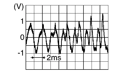
Is the inspection result normal?
YES>>
Replace Bose speaker amp. Refer to Removal and Installation.
NO>>
Replace AV control unit. Refer to Removal and Installation.
Sound Signal Rh
Diagnosis Procedure
CONNECTOR CHECK
Check the AV control unit and Bose speaker amp. connectors for the following:
-
Proper connection
-
Damage
-
Disconnected or loose terminals
Is the inspection result normal?
YES>>
GO TO 2.
NO>>
Repair the terminals or connectors.
CHECK SOUND SIGNAL RH CIRCUIT CONTINUITY
-
Ignition switch OFF.
-
Disconnect Bose speaker amp. connector B129 and AV control unit connector M148.
-
Check continuity between Bose speaker amp. connector B129 and AV control unit connector M148.
Bose speaker amp. AV control unit Continuity Connector Terminal Connector Terminal B129 2 M148 11 Yes 22 12 -
Check continuity between Bose speaker amp. connector B129 and ground.
Bose speaker amp. Ground Continuity Connector Terminal B129 2 — No 22
Is the inspection result normal?
YES>>
GO TO 3.
NO>>
Repair or replace harness or connectors.
CHECK SOUND SIGNAL RH
-
Connect Bose speaker amp. connector B129 and AV control unit connector M148.
-
Ignition switch ON.
-
Push AV control unit POWER switch.
-
Check signal between the terminals of AV control unit connector M148 connectors.
AV control unit connector M148 Condition Reference value (+) (−) Terminal Terminal 11 12 Audio signal output 
Is the inspection result normal?
YES>>
Replace Bose speaker amp. Refer to Removal and Installation.
NO>>
Replace AV control unit. Refer to Removal and Installation.
Voice Guidance Signal Circuit
Diagnosis Procedure
CONNECTOR CHECK
Check the AV control unit and Bose speaker amp. connectors for the following:
-
Proper connection
-
Damage
-
Disconnected or loose terminals
Is the inspection result normal?
YES>>
GO TO 2.
NO>>
Repair the terminals or connectors.
CHECK VOICE GUIDANCE SIGNAL CIRCUIT CONTINUITY
-
Ignition switch OFF.
-
Disconnect Bose speaker amp. connector B129 and AV control unit connector M148.
-
Check continuity between Bose speaker amp. connector B129 and AV control unit connector M148.
Bose speaker amp. AV control unit Continuity Connector Terminal Connector Terminal B129 3 M148 4 Yes 23 5 -
Check continuity between Bose speaker amp. connector B129 and ground.
Bose speaker amp. (–) Continuity Connector Terminal B129 3 Ground No 23
Is the inspection result normal?
YES>>
GO TO 3.
NO>>
Repair or replace harness or connectors.
CHECK VOICE GUIDANCE SIGNAL
-
Connect Bose speaker amp. connector B129 and AV control unit connector M148.
-
Ignition switch ON.
-
Push AV control unit POWER switch.
-
Check signal between the terminals of AV control unit connector M148 connectors.
AV control unit connector M148 Condition Reference value (+) (−) Terminal Terminal 4 5 Guidance signal output 
Is the inspection result normal?
YES>>
Replace Bose speaker amp. Refer to Removal and Installation.
NO>>
Replace AV control unit. Refer to Removal and Installation.
Steering Switch
Diagnosis Procedure
CHECK STEERING WHEEL AUDIO CONTROL SWITCH RESISTANCE
-
Ignition switch OFF.
-
Disconnect combination switch (spiral cable) connector M149.
-
Check resistance between the terminals of combination switch (spiral cable) connector M149.
| Combination switch (spiral cable) connector M149 | Condition |
Resistance Ω (Approx.) |
|
|---|---|---|---|
| Terminal | Terminal | ||
| 27 | 25 | Depress CONTROL switch. | 1 |
Depress  switch. switch. |
51 | ||
Depress  switch. switch. |
133 | ||
| Depress OK switch. | 263 | ||
| Depress LEFT/BACK switch. | 653 | ||
| Depress RIGHT switch. | 2123 | ||
| 23 | Depress   switch. switch. |
1 | |
Depress   switch. switch. |
51 | ||
Depress  switch. switch. |
133 | ||
Depress  switch. switch. |
263 | ||
| Depress SEEK DOWN switch. | 653 | ||
| Depress SEEK UP switch. | 2123 | ||
Is the inspection result normal?
YES>>
GO TO 2.
NO>>
Replace steering switches. Refer to Removal and Installation.
CHECK HARNESS BETWEEN COMBINATION METER AND COMBINATION SWITCH (SPIRAL CABLE)
-
Disconnect combination meter connector M24 (with 7" information display meter) or M44 (with full TFT meter) and combination switch (spiral cable) connector M30.
-
Check continuity between combination meter connector M24 (with 7" information display meter) or M44 (with full TFT meter) and combination switch (spiral cable) connector M30.
Combination meter Combination switch (spiral cable) Continuity Connector Terminal Connector Terminal M24 (with 7" information display meter)
M44 (with full TFT meter)23 M30 9 Yes 33 13 34 11 -
Check continuity between combination meter connector M24 (with 7" information display meter) or M44 (with full TFT meter) and ground.
Combination meter Ground Continuity Connector Terminal M24 (with 7" information display meter)
M44 (with full TFT meter)23 — No 33 34
Is the inspection result normal?
YES>>
GO TO 3.
NO>>
Repair or replace harness or connectors.
CHECK COMBINATION SWITCH (SPIRAL CABLE)
Check continuity between combination switch (spiral cable) connectors M149 and M30.
| Combination switch (spiral cable) | Continuity | |||
|---|---|---|---|---|
| Connector | Terminal | Connector | Terminal | |
| M149 | 22 | M30 | 16 | Yes |
| 23 | 9 | |||
| 25 | 11 | |||
| 27 | 13 | |||
Is the inspection result normal?
YES>>
GO TO 4.
NO>>
Replace spiral cable. Refer to Removal and Installation.
CHECK HARNESS BETWEEN COMBINATION METER AND AV CONTROL UNIT
-
Disconnect combination meter connector M24 (with 7" information display meter) or M44 (with full TFT meter) and AV control unit connector M123 (without Bose audio system) or M160 (with Bose audio system).
-
Check continuity between combination meter connector M24 (with 7" information display meter) or M44 (with full TFT meter) and AV control unit connector M123 (without Bose audio system) or M160 (with Bose audio system).
Combination meter AV control unit Continuity Connector Terminal Connector Terminal M24 (with 7" information display meter)
M44 (with full TFT meter)39 M123 (without Bose audio system)
M160 (with Bose audio system)42 Yes 43 40 22 23 -
Check continuity between combination meter connector M24 (with 7" information display meter) or M44 (with full TFT meter) and ground.
Combination meter Ground Continuity Connector Terminal M24 (with 7" information display meter)
M44 (with full TFT meter)39 — No 40
Is the inspection result normal?
YES>>
Replace AV control unit. Refer to Removal and Installation.
NO>>
Repair or replace harness or connectors.
Front Auxiliary Input Jacks
Diagnosis Procedure
CHECK USB INTERFACE HARNESS CONTINUITY
-
Ignition switch OFF.
-
Disconnect AV control unit connector M124 (without Bose audio system) or M180 (with Bose audio system) and front auxiliary input jacks connector M166.
-
Check continuity between AV control unit connector M124 (without Bose audio system) or M180 (with Bose audio system) and front auxiliary input jacks connector M166.
AV control unit Front auxiliary input jacks Continuity Connector Terminal Connector Terminal M124 (without Bose audio system)
M180 (with Bose audio system)61 M166 9 Yes 63 11 64 12 65 13 66 14 -
Check continuity between AV control unit connector M124 (without Bose audio system) or M180 (with Bose audio system) and ground.
AV control unit — Continuity Connector Terminal M124 (without Bose audio system)
M180 (with Bose audio system)63 Ground No 65
Is the inspection result normal?
YES>>
Replace the front auxiliary input jacks. Refer to Removal and Installation.
NO>>
Repair or replace harness or connectors.

Nissan Pathfinder (R53) 2022-2026 Service Manual
Contact Us
Nissan Pathfinder Info Center
Email: info@nipathfinder.com
Phone: +1 (800) 123-4567
Address: 123 Pathfinder Blvd, Nashville, TN 37214, USA
Working Hours: Mon–Fri, 9:00 AM – 5:00 PM (EST)
