Nissan Pathfinder: Exterior Lighting System - Led Headlamp
- Precautions
- Preparation
- Ecu Diagnosis Information. Bcm, Ipdm E/r
- Unit Disassembly and Assembly. Rear Combination Lamp (body Side)
- Service Data and Specifications (SDS)
Precautions Nissan Pathfinder
Precaution for Supplemental Restraint System (SRS) "AIR BAG" and "SEAT BELT PRE-TENSIONER"
The Supplemental Restraint System such as “AIR BAG” and “SEAT BELT PRE-TENSIONER”, used along with a front seat belt, helps to reduce the risk or severity of injury to the driver and front passenger for certain types of collisions.
Information necessary to service the system safely is included in the “SRS AIR BAG” and “SEAT BELT” sections of this Service Manual.
WARNING:
Always observe the following items for preventing accidental activation:
-
To avoid rendering the SRS inoperative, which could increase the risk of personal injury or death in the event of a collision that would result in air bag inflation, it is recommended that all maintenance and repair be performed by an authorized NISSAN/INFINITI dealer.
-
Improper repair, including incorrect removal and installation of the SRS, can lead to personal injury caused by unintentional activation of the system. For removal of Spiral Cable and Air Bag Module, see “SRS AIR BAG”.
-
Never use electrical test equipment on any circuit related to the SRS unless instructed to in this Service Manual. SRS wiring harnesses can be identified by yellow and/or orange harnesses or harness connectors.
PRECAUTIONS WHEN USING POWER TOOLS (AIR OR ELECTRIC) AND HAMMERS
WARNING:
Always observe the following items for preventing accidental activation:
-
When working near the Air Bag Diagnosis Sensor Unit or other Air Bag System sensors with the ignition/power switch ON or engine running, never use air or electric power tools or strike near the sensor(s) with a hammer. Heavy vibration could activate the sensor(s) and deploy the air bag(s), possibly causing serious injury.
-
When using air or electric power tools or hammers, always switch the ignition/power switch OFF, disconnect the 12V battery or batteries, and wait at least 3 minutes before performing any service.
Precautions for Work
-
When removing or disassembling each component, be careful not to damage or deform it. If a component may be subject to interference, be sure to protect it with a shop cloth.
-
When removing (disengaging) components with a screwdriver or similar tool, be sure to wrap the component with a shop cloth or vinyl tape to protect it.
-
Protect the removed parts with a shop cloth and prevent them from being dropped.
-
Replace a deformed or damaged clip.
-
If a part is specified as a non-reusable part, always replace it with a new one.
-
Be sure to tighten bolts and nuts securely to the specified torque.
-
After installation is complete, be sure to check that each part works properly.
-
Follow the steps below to clean components:
-
Water soluble dirt:
-
Dip a soft cloth into lukewarm water, wring the water out of the cloth and wipe the dirty area.
-
Then rub with a soft, dry cloth.
-
-
Oily dirt:
-
Dip a soft cloth into lukewarm water with mild detergent (concentration: within 2 to 3%) and wipe the dirty area.
-
Then dip a cloth into fresh water, wring the water out of the cloth and wipe the detergent off.
-
Then rub with a soft, dry cloth.
-
-
Do not use organic solvent such as thinner, benzene, alcohol or gasoline.
-
For genuine leather seats, use a genuine leather seat cleaner.
-
Preparation Nissan Pathfinder 2026
Special Service Tool
|
Tool number (TechMate No.) Tool name | Description | |
|---|---|---|
|
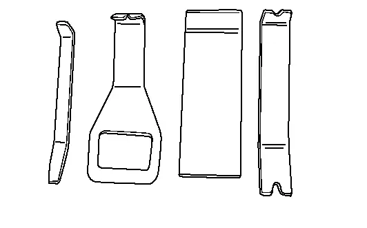
— (NI-46534) Trim Tool Set |
|
Removing trim components |
Always Replace with New Parts
| Never Reuse These Parts | Part Code | For additional information: |
|---|---|---|
| CLIP | 26075E | REAR COMBINATION LAMP (BODY SIDE) EXPLODED VIEW |
Ecu Diagnosis Information. Bcm, Ipdm E/r Nissan Pathfinder
List of ECU Reference
| ECU | Reference |
|---|---|
| BCM | Values on the Diagnosis Tool |
| Reference Value | |
| Fail-safe | |
| DTC Inspection Priority Chart | |
| DTC Index | |
| IPDM E/R | Values on the Diagnosis Tool |
| Reference Value | |
| Fail-safe | |
| DTC Inspection Priority Chart | |
| DTC Index |
Unit Disassembly and Assembly. Rear Combination Lamp (body Side) Nissan Pathfinder R53
Exploded View
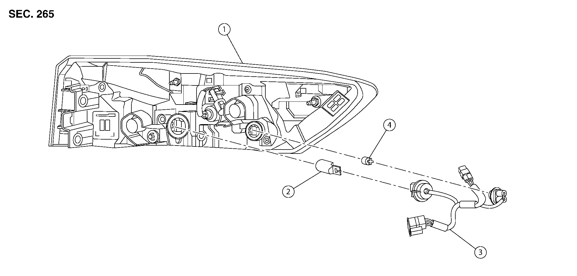
| 1. | Rear combination lamp | 2. | Rear turn signal lamp bulb | 3. | Rear combination lamp harness |
| 4. | Side marker lamp bulb |
Disassembly and Assembly
WARNING:
Do not touch bulb by hand while it is lit or right after being turned off. Burning may result.
CAUTION:
-
After installing, be sure to install the bulb sockets securely to ensure watertightness.
-
Do not touch glass surface of the bulb with bare hands or allow oil or grease to get on it to prevent damage to bulb.
-
Do not leave bulb out of lamp reflector for a long time because dust, moisture, smoke, etc. may affect the performance of lamp. When replacing bulb, be sure to replace it with new one.
DISASSEMBLY
Remove rear combination lamp. Refer to Removal and Installation.
Rotate rear turn signal lamp bulb socket counterclockwise and remove.
Remove rear turn signal bulb from bulb socket.
Rotate side marker lamp bulb socket counterclockwise and remove.
Remove side marker bulb from bulb socket.
ASSEMBLY
Assembly is in the reverse order of disassembly.
CAUTION:
After installing, be sure to install the bulb sockets securely to ensure watertightness.
Service Data and Specifications (SDS) Nissan Pathfinder 2026
Bulb Specifications
| Item | Wattage (W) * | |
|---|---|---|
| Front combination lamp | High beam | — |
| Low beam | — | |
| Front turn signal lamp | 28/8 | |
| Side marker lamp | — | |
| Parking/Daytime running lamp | — | |
| Front fog lamp | Fog lamp (If equipped) | — |
| Rear combination lamp (body side) | Stop/Tail lamp | — |
| Turn signal lamp | 21 | |
| Side marker lamp | 5 | |
| Rear combination lamp (back door side) | Tail lamp | — |
| Back-up lamp | 16 | |
| Turn signal lamp (door mirror) | — | |
| License plate lamp | — | |
| High-mounted stop lamp | — | |
*: Always check with the Parts Department for the latest parts info.

Nissan Pathfinder (R53) 2022-2026 Service Manual
Led Headlamp
- Precautions
- Preparation
- Ecu Diagnosis Information. Bcm, Ipdm E/r
- Unit Disassembly and Assembly. Rear Combination Lamp (body Side)
- Service Data and Specifications (SDS)
Contact Us
Nissan Pathfinder Info Center
Email: info@nipathfinder.com
Phone: +1 (800) 123-4567
Address: 123 Pathfinder Blvd, Nashville, TN 37214, USA
Working Hours: Mon–Fri, 9:00 AM – 5:00 PM (EST)
