Nissan Pathfinder: Power Control System - Ipdm E/r
- Precautions
- Ecu Diagnosis Information. Ipdm E/r
- Removal and Installation. Ipdm E/r (intelligent Power Distribution Module Engine Room)
Precautions Nissan Pathfinder 2026
Precaution for Supplemental Restraint System (SRS) "AIR BAG" and "SEAT BELT PRE-TENSIONER"
The Supplemental Restraint System such as “AIR BAG” and “SEAT BELT PRE-TENSIONER”, used along with a front seat belt, helps to reduce the risk or severity of injury to the driver and front passenger for certain types of collisions.
Information necessary to service the system safely is included in the “SRS AIR BAG” and “SEAT BELT” sections of this Service Manual.
WARNING:
Always observe the following items for preventing accidental activation:
-
To avoid rendering the SRS inoperative, which could increase the risk of personal injury or death in the event of a collision that would result in air bag inflation, it is recommended that all maintenance and repair be performed by an authorized NISSAN/INFINITI dealer.
-
Improper repair, including incorrect removal and installation of the SRS, can lead to personal injury caused by unintentional activation of the system. For removal of Spiral Cable and Air Bag Module, see “SRS AIR BAG”.
-
Never use electrical test equipment on any circuit related to the SRS unless instructed to in this Service Manual. SRS wiring harnesses can be identified by yellow and/or orange harnesses or harness connectors.
PRECAUTIONS WHEN USING POWER TOOLS (AIR OR ELECTRIC) AND HAMMERS
WARNING:
Always observe the following items for preventing accidental activation:
-
When working near the Air Bag Diagnosis Sensor Unit or other Air Bag System sensors with the ignition/power switch ON or engine running, never use air or electric power tools or strike near the sensor(s) with a hammer. Heavy vibration could activate the sensor(s) and deploy the air bag(s), possibly causing serious injury.
-
When using air or electric power tools or hammers, always switch the ignition/power switch OFF, disconnect the 12V battery or batteries, and wait at least 3 minutes before performing any service.
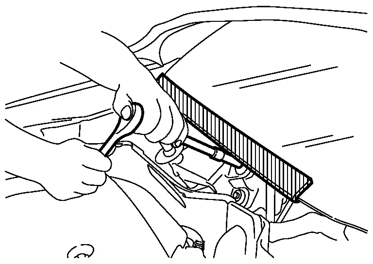
Procedure without Cowl TopCover
When performing the procedure after removing cowl top cover, cover the lower end of windshield with urethane, etc. to prevent damage to the windshield.
Ecu Diagnosis Information. Ipdm E/r Nissan Pathfinder SUV
Values on the Diagnosis Tool
 NOTE:
NOTE:
The following table includes information (items) inapplicable to this Nissan Pathfinder vehicle. For information (items) applicable to this vehicle, refer to CONSULT display items.
| Monitor | Condition | Value/Status | |
|---|---|---|---|
| Compressor request 1 | Engine running | A/C switch OFF | Off |
| A/C switch ON (A/C compressor is operating) | On | ||
| Easy fill tire alert horn req |
This item is indicated, but not monitored. |
Off | |
| Cranking enable-TCM | Engine crank condition | Not satisfied | Prohibit |
| Satisfied | Permit | ||
| — | Stop | ||
| Receives invalid CAN signal | Unknown | ||
| Cranking enable-ECM | Engine crank condition | Not satisfied | Prohibit |
| Satisfied | Permit | ||
| — | Stop | ||
| Receives invalid CAN signal | No req | ||
| DTRL REQ | Engine running | Lighting switch 1ST | Off |
| Lighting switch OFF | On | ||
| COOLING FAN REQ | Engine running | Cooling fan stop | 10% |
| Cooling fan LO operation | 42% | ||
| Cooling fan HI operation | 90% | ||
| FR WIPER REQ | Receives invalid CAN signal | NG | |
| Ignition switch ON | Front wiper HI operation | HIGH | |
| Front wiper LO operation | LOW | ||
| Front wiper forced termination | STOP | ||
| Front wiper stopped | RETURN | ||
| HIGH BEAM REQ | Lighting switch 2ND | Lighting switch LO | Off |
| Lighting switch HI | On | ||
| Horn request |
This item is indicated, but not monitored. |
No req | |
| Low beam request | Lighting switch OFF | Off | |
| Lighting switch 2ND | On | ||
| POSITION LIGHT REQ | Lighting switch OFF | Off | |
| Lighting switch 1ST | On | ||
| IGNITION SW | Ignition switch OFF | Off | |
| Ignition switch ON | On | ||
| Ignition switch START | START | ||
| — | No request | ||
|
FRONT FOG LAMP REQ
This item is monitored only on the Nissan Pathfinder vehicle with front fog lamp. |
Lighting switch 1ST | Front fog lamp switch OFF | Off |
| Front fog lamp switch ON | On | ||
| Shift position | Receives invalid CAN signal | NG | |
| Engine running | Manual mode | M | |
| D range | D | ||
| N range | N | ||
| R range | R | ||
| P range | P | ||
| COMP ECV STATUS | ECV control output | Normal | OK |
| Malfunction | NG | ||
| BATTERY VOLTAGE | Ignition switch ON | 11 V – 14 V | |
| Stop/start status | — | — | — |
| — | — | — | |
| FR WIPER STOP POSITION | Ignition switch ON | Except front wiper stop position | ACTIVE P |
| Front wiper stop position | STOP P | ||
| IGNITION POWER SUPPLY |
This item is indicated, but not monitored. |
Off | |
|
HOOD SW (CAN)
This item is monitored only on the Nissan Pathfinder vehicle with Stop/Start system. |
Open the hood | OPEN | |
| Close the hood | CLOSE | ||
| Transmits invalid CAN signal | NG | ||
| A/C RELAY | Engine running | A/C switch OFF | Off |
| A/C switch ON (A/C compressor is operating) | On | ||
| REVERSE SIGNAL (CAN) | Transmits invalid CAN signal | NG | |
| Ignition switch ON | R range | On | |
| Except R range | Off | ||
| COMP ECV CURRENT | Engine running | A/C switch OFF | 0.00 A |
| A/C switch ON (A/C compressor is operating) | 0.00 A – 1.00 A | ||
| Starter&starter cont relay stat | Starter relay and starter control relay are OFF | Off, Off | |
| Starter relay is ON | On, Off | ||
| Starter relay and starter control relay are ON | On, On | ||
| Transmits invalid CAN signal | invalid | ||
|
Hood switch
This item is monitored only on the Nissan Pathfinder vehicle with Remote engine start system. |
Close the hood | Open | |
| Open the hood | Close | ||
| IGN RELAY | Ignition switch OFF | Open | |
| Ignition switch ON | Close | ||
| Cooling fan relay-2 | Engine running | Cooling fan stop | OFF |
|
ON | ||
| Compressor | Engine running | A/C switch OFF | OFF |
| A/C switch ON (A/C compressor is operating | ON | ||
| Front wiper HI/LO relay | Ignition switch ON | Except front wiper HI operated | OFF |
| Front wiper HI operated | ON | ||
| Horn relay |
This item is indicated, but not monitored. |
OFF | |
| Front wiper relay | Ignition switch ON | Front wiper stop | OFF |
| Front wiper is operating | ON | ||
| Battery current sen value (LIN) |
Engine running
|
(–200.00) – (+300.00) A | |
| Headlamp warning (LH) (LIN) | Lighting switch OFF | Open | |
| Lighting switch 2ND | Close | ||
| Headlamp warning (RH) (LIN) | Lighting switch OFF | Open | |
| Lighting switch 2ND | Close | ||
| Compressor ECV duty | Engine running | A/C switch OFF | 0% |
| A/C switch ON (A/C compressor is operating | 0 – 100% | ||
| Cooling fan relay-3 | Engine running |
|
0% |
| Cooling fan HI operated | 100% | ||
|
Front fog lamp (LH)
This item is monitored only on the Nissan Pathfinder vehicle with front fog lamp. |
Lighting switch 1ST | Front fog lamp switch OFF | 0% |
| Front fog lamp switch ON | 100% | ||
|
Front fog lamp (RH)
This item is monitored only on the Nissan Pathfinder vehicle with front fog lamp. |
Lighting switch 1ST | Front fog lamp switch OFF | 0% |
| Front fog lamp switch ON | 100% | ||
| Tail lamp (LH) | Lighting switch OFF | 0.0% | |
| Lighting switch 1ST | 100.0% | ||
| Tail lamp (RH) | Lighting switch OFF | 0% | |
| Lighting switch 1ST | 100% | ||
| Headlamp LO (RH) | Lighting switch OFF | 0% | |
| Lighting switch 2ND | 100% | ||
| Headlamp LO (LH) | Lighting switch OFF | 0% | |
| Lighting switch 2ND | 100% | ||
| Parking lamp (LH) req (LIN) |
|
Close | |
| Lighting switch 1ST | Open | ||
| DTRL (LH) req (LIN) | Engine running and parking brake is released | Lighting switch 2ND | Close |
|
Open | ||
| Headlamp LO (LH) req (LIN) |
|
Close | |
| Lighting switch 2ND | Open | ||
| Headlamp HI (LH) req (LIN) | Lighting switch 2ND | Lighting switch LO | Close |
| Lighting switch HI | Open | ||
| Parking lamp (RH) req (LIN) |
|
Close | |
| Lighting switch 1ST | Open | ||
| DTRL (RH) req (LIN) | Engine running and parking brake is released | Lighting switch 2ND | Close |
|
Open | ||
| Parking/DTRL (LH) output (LIN) | Engine running and parking brake is released |
|
100.0% |
| Lighting switch 2ND | 6.0% | ||
| Engine stop |
|
0.0% | |
| Parking/DTRL (RH) output (LIN) | Engine running and parking brake is released |
|
100.0% |
| Lighting switch 2ND | 6.0% | ||
| Engine stop |
|
0.0% | |
| Headlamp HI (RH) req (LIN) | Lighting switch 2ND | Lighting switch LO | Close |
| Lighting switch HI | Open | ||
| Headlamp LO (RH) req (LIN) |
|
Close | |
| Lighting switch 2ND | Open | ||
| Battery status | — | — | |
| — | — | ||
| T LAMP LH CIRC MALFUNCTN | Tail lamp LH power supply circuit reaches the retry upper limit. | 0 – 1 | |
| NMB T LAMP LH CIRC RETRY | Retry of tail lamp LH power supply circuit is permitted. | 0 – 20 | |
|
Fr fog lamp (LH) circ malfunctn
This item is monitored only on the Nissan Pathfinder vehicle with front fog lamp. |
Front fog lamp LH circuit reaches the retry upper limit. | 0 – 1 | |
| T LAMP RH CIRC MALFUNCTN | Tail lamp RH power supply circuit reaches the retry upper limit. | 0 – 1 | |
| NMB T LAMP RH CIRC RETRY | Retry of tail lamp RH power supply circuit is permitted. | 0 – 20 | |
| NMB T LAMP RH CIRC SHORT | Tail lamp RH power supply circuit detects over current. | 0 – 5 | |
|
NMB F FOG LH CIRC RETRY
This item is monitored only on the Nissan Pathfinder vehicle with front fog lamp. |
Retry of front fog lamp LH circuit is permitted. | 0 – 20 | |
|
NMB F FOG LH CIRC SHORT
This item is monitored only on the Nissan Pathfinder vehicle with front fog lamp. |
Front fog lamp LH circuit detects over current. | 0 – 5 | |
|
F FOG RH CIRC MALFUNCTN
This item is monitored only on the Nissan Pathfinder vehicle with front fog lamp. |
Front fog lamp RH circuit reaches the retry upper limit. | 0 – 1 | |
|
NMB F FOG RH CIRC RETRY
This item is monitored only on the Nissan Pathfinder vehicle with front fog lamp. |
Retry of front fog lamp RH circuit is permitted. | 0 – 20 | |
|
NMB F FOG RH CIRC SHORT
This item is monitored only on the Nissan Pathfinder vehicle with front fog lamp. |
Front fog lamp RH circuit detects over current. | 0 – 5 | |
| NMB T LAMP LH CIRC SHORT | Tail lamp LH power supply circuit detects over current. | 0 – 5 | |
|
BAT DISCHARGE COUNT
This item is monitored only on the Nissan Pathfinder vehicle with Stop/Start system. |
Ignition switch ON | Less than 65000 | |
 NOTE:
NOTE:
 NOTE:
NOTE:
 NOTE:
NOTE:
 NOTE:
NOTE:
 NOTE:
NOTE:
 NOTE:
NOTE:
 NOTE:
NOTE:
 NOTE:
NOTE:
 NOTE:
NOTE:
 NOTE:
NOTE:
 NOTE:
NOTE:
 NOTE:
NOTE:
 NOTE:
NOTE:
 NOTE:
NOTE:
 NOTE:
NOTE:
 NOTE:
NOTE:
Reference Value
TERMINAL LAYOUT
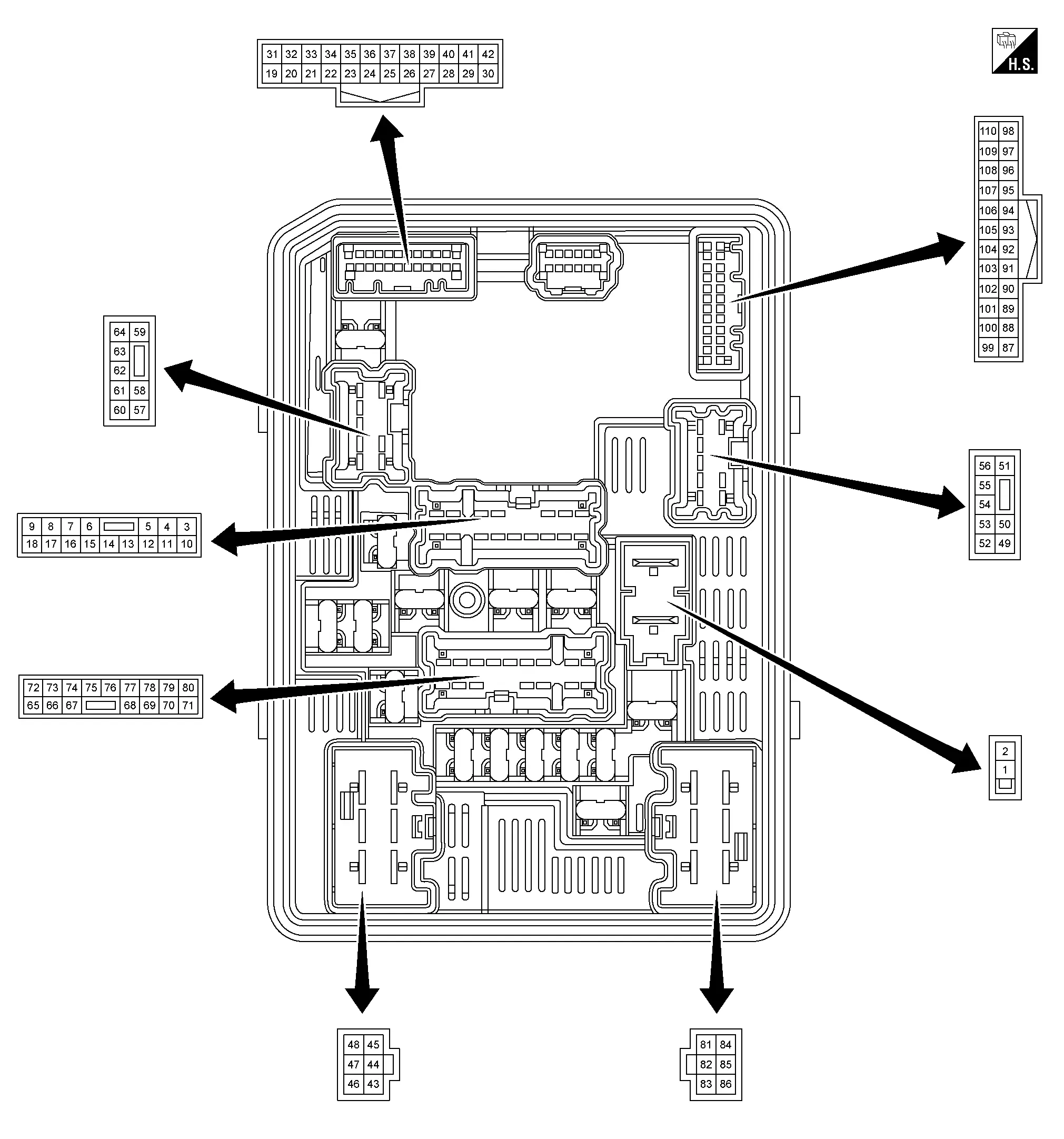
PHYSICAL VALUES
|
Terminal No. (Wire color) | Description | Condition |
Value (Approx.) | |||
|---|---|---|---|---|---|---|
| Signal name | Input/Output | |||||
| + | - | |||||
|
1 (L) |
Ground | Battery power supply | Input | Ignition switch OFF | Battery voltage | |
|
2 (G) |
Ground | Battery power supply | Input | Ignition switch OFF | Battery voltage | |
|
4 (W) |
Ground | Tail lamp LH power supply | Output | Lighting switch OFF | 0 V | |
| Lighting switch 1ST | Battery voltage | |||||
|
8 (BG) |
Ground | ECM relay output | Output | Ignition switch OFF (more than a few seconds after placing ignition switch ON) | 0 V | |
| For a few seconds after placing ignition switch OFF or ignition switch ON | Battery voltage | |||||
|
9 (Y) |
Ground | Horn relay control | Input | Horn switch OFF | Battery voltage | |
| Horn switch ON | 0 V | |||||
|
12 (B) |
Ground | Ground | — | Ignition switch OFF | 0 V | |
|
17 (G) |
Ground | Tail lamp RH power supply | Output | Lighting switch OFF | 0 V | |
| Lighting switch 1ST | Battery voltage | |||||
|
22 (P) |
Ground | CAN-Low | Input/Output | — | — | |
|
24 (L) |
Ground | CAN-High | Input/Output | — | — | |
|
31 (B) |
Ground | Ground | — | Ignition switch OFF | 0 V | |
|
33 (BR) |
Ground | Front wiper auto stop signal | Input | Ignition switch ON | Front wiper stop position | 0 V |
| Other than above | Battery voltage | |||||
|
38 (R) |
Ground | LIN communication (headlamp) | Input/output | Ignition switch ON |
|
|
|
43 (W) |
Ground | Ignition relay output | Output | Ignition switch OFF | 0 V | |
| Ignition switch ON | Battery voltage | |||||
|
45 (L) |
Ground | Front wiper motor HI power supply | Output | Ignition switch ON | Front wiper switch OFF | 0 V |
| Front wiper switch HI | Battery voltage | |||||
|
46 (V) |
Ground | Fuel pump power supply | Output | More than a few seconds after placing ignition switch ON or ignition switch OFF | 0 V | |
| For a few seconds after placing ignition switch ON or engine running | Battery voltage | |||||
|
47 (B) |
Ground | Ground | — | Ignition switch ON | 0 V | |
|
48 (Y) |
Ground | Front wiper motor LO power supply | Output | Ignition switch ON | Front wiper switch OFF | 0 V |
| Front wiper switch LO | Battery voltage | |||||
|
50 (L) |
Ground | Headlamp (LO) LH power supply | Output | Lighting switch OFF | 0 V | |
| Lighting switch 2ND | Battery voltage | |||||
|
511 (Y) |
Ground | Front fog lamp LH power supply | Output | Lighting switch 1ST | Front fog lamp switch OFF | 0 V |
| Front fog lamp switch ON | Battery voltage | |||||
|
52 (R) |
Ground | Hood switch signal | Input | Close the hood | 0 V | |
| Open the hood | Battery voltage | |||||
|
571 (W) |
Ground | Front fog lamp RH power supply | Output | Lighting switch 1ST | Front fog lamp switch OFF | 0 V |
| Front fog lamp switch ON | Battery voltage | |||||
|
62 (P) |
Ground | Headlamp (LO) RH power supply | Output | Lighting switch OFF | 0 V | |
| Lighting switch 2ND | Battery voltage | |||||
|
65 (SB) |
Ground | A/C compressor power supply | Output | Engine running | A/C switch OFF | 0 V |
|
A/C switch ON (A/C compressor is operating) |
Battery voltage | |||||
|
67 (G) |
Ground | Throttle control motor relay control | Input | Ignition switch ON –> OFF | Battery voltage | |
| Ignition switch ON | 0 V | |||||
|
70 (P) |
Ground | Ignition relay output | Output | Ignition switch OFF | 0 V | |
| Ignition switch ON | Battery voltage | |||||
|
71 (L) |
Ground | Ignition relay output | Output | Ignition switch OFF | 0 V | |
| Ignition switch ON | Battery voltage | |||||
|
72 (R) |
Ground | Throttle control motor relay output | Output | Ignition switch OFF (more than a few seconds after placing ignition switch ON) | 0 V | |
| For a few seconds after placing ignition switch OFF or ignition switch ON | Battery voltage | |||||
|
73 (LG) |
Ground | ECM relay output | Output | Ignition switch OFF (more than a few seconds after placing ignition switch ON) | 0 V | |
| For a few seconds after placing ignition switch OFF or ignition switch ON | Battery voltage | |||||
|
75 (W) |
Ground | ECM relay output | Output | Ignition switch OFF (more than a few seconds after placing ignition switch ON) | 0 V | |
| For a few seconds after placing ignition switch OFF or ignition switch ON | Battery voltage | |||||
|
76 (P) |
Ground | Fuel pump relay control | Input | Approximately 1 second after placing the ignition switch ON or ignition switch OFF | 0 V | |
| Approximately 1 second or more placing the ignition switch ON | Battery voltage | |||||
|
78 (L) |
Ground | ECM relay output | Output | Ignition switch OFF (more than a few seconds after placing ignition switch ON) | 0 V | |
| For a few seconds after placing ignition switch OFF or ignition switch ON | Battery voltage | |||||
|
81 (R) |
Ground | Battery power supply | Input | Ignition switch OFF | Battery voltage | |
|
83 (W) |
Ground | Starter motor power supply | Output | Other than at engine cranking | 0 V | |
| At engine cranking | Battery voltage | |||||
|
86 (V) |
Ground | Starter relay power supply | Input | Other than at engine cranking | 0 V | |
| At engine cranking | Battery voltage | |||||
|
91 (R) |
Ground | LIN communication (battery current sensor) | Input/output | Ignition switch ON |
|
|
|
93 (V) |
Ground | ECM relay control | Input | Ignition switch OFF (more than a few seconds after placing ignition switch ON) | Battery voltage | |
| For a few seconds after placing ignition switch OFF or ignition switch ON | 0 V | |||||
|
98 (W) |
Ground | A/C compressor (ECV) control | Output | ECV | Duty ratio: 0% (MODE5 or MODE6) | 0 V |
| Duty ratio: 50% (MODE3 or MODE4) |
|
|||||
| Duty ratio: 100% (MODE1, MODE2 or MODE7) | Battery voltage | |||||
|
1042 (L) |
Ground | Starter switch signal | — | — | — | |
|
106 (V) |
Ground | Cooling fan control | Output | Engine running | Cooling fan stop | Battery voltage |
|
0 V | |||||
|
107 (B) |
Ground | Cooling fan control | Output | Engine running |
|
Battery voltage |
| Cooling fan HI operated | 0 V | |||||

1: With front fog lamps or pre-wiring for front fog lamps
2: Except for Mexico
Fail-safe
FAIL-SAFE CONTROL BY DTC
IPDM E/R performs fail-safe control when any DTC are detected.
| DTC No. | CONSULT display | Fail-safe | |
|---|---|---|---|
| B121A-11 | FR FOG LAMP LH PWR SPLY CIRC | [CIRCUIT SHORT TO GROUND] | Shuts off the power supply to the front fog lamp LH power supply circuit until the front fog lamp ON conditions are no longer satisfied. |
| B1256-11 | FR FOG LAMP RH PWR SPLY CIRC | [CIRCUIT SHORT TO GROUND] | Shuts off the power supply to the front fog lamp RH power supply circuit until the front fog lamp ON conditions are no longer satisfied. |
| B12A4-81 | Battery current sensor | [INVALID SERIAL DATA RECEIVED] | Fix the power generation command value to 14.3 V. |
| B12A4-92 | Battery current sensor | [PFM/INCORRECT OPERATN] | |
| B20A2-87 | Headlamp (RH) LIN communication | [MISSING MESSAGE] |
|
| B20A4-87 | Headlamp (LH) LIN communication | [MISSING MESSAGE] | |
| B20C7-11 | A/C clutch | [CIRCUIT SHORT TO GROUND] | Inhibit A/C compressor (magnetic clutch) operation |
| B20C7-15 | A/C clutch | [CIRC SHORT TO BATT OR OPEN] | |
| B20C8-14 | Compressor (ECV) | [CIRC SHORT TO GRND OR OPEN] | Inhibit compressor (ECV) operation |
| B20D4-11 | TAIL LAMP LH PWR SPLY CIRC | [CIRCUIT SHORT TO GROUND] |
Shuts off the power supply to the following power supply circuits until the parking lamp, license plate lamp, side marker lamp and tail lamp ON conditions are no longer satisfied:
|
| B20D5-11 | TAIL LAMP RH PWR SPLY CIRC | [CIRCUIT SHORT TO GROUND] |
Shuts off the power supply to the following power supply circuits until the parking lamp, license plate lamp, side marker lamp and tail lamp ON conditions are no longer satisfied:
|
| B20E2-96 | LED HEADLAMP RH | [CMPNENT INTERNAL MLFNCTN] |
|
| B20E3-96 | LED HEADLAMP LH | [CMPNENT INTERNAL MLFNCTN] | |
| U0073-00 | Control module comm Bus A Off | [NO SUBTYPE INFO] | Refer to CAN COMMUNICATION CONTROL. |
| U2140-87 | CAN comm err (ECM) | [MISSING MESSAGE] | |
| U214F-87 | CAN comm err (BCM) | [MISSING MESSAGE] | |
CAN COMMUNICATION CONTROL
When CAN communication with the ECM and BCM is impossible, the IPDM E/R performs fail-safe control. After CAN communication recovers normally, it also returns to normal control.
If No CAN Communication Is Available With ECM
| Control part | Fail-safe operation |
|---|---|
| Cooling fan |
|
| A/C Compressor (magnet clutch) | Smart FET OFF |
If No CAN Communication Is Available With BCM
| Control part | Fail-safe operation |
|---|---|
| Headlamp |
|
|
|
| Front wiper |
|
| Daytime running light | Daytime running light: OFF |
| Front fog lamp | Front fog lamp: OFF |
| Ignition relay | The status just before activation of fail-safe is maintained. |
| Starter motor | Starter relay: OFF |
IGNITION RELAY CONTROL
-
The IPDM E/R monitors the voltage at the contact circuit of the ignition relay inside it.
-
The IPDM E/R judges the ignition relay error if the voltage differs between the contact circuit.
| Voltage judgement | IPDM E/R judgement | Operation | |
|---|---|---|---|
| Ignition relay contact side | Ignition relay control condition | ||
| ON | ON | Ignition relay ON normal | — |
| OFF | OFF | Ignition relay OFF normal | — |
| ON | OFF | Ignition relay ON stuck | Detects DTC [B20DD-73: IGN RELAY ON CIRC] |
| OFF | ON | Ignition relay OFF stuck | Detects DTC [B20DE-72: IGN RELAY OFF CIRC] |
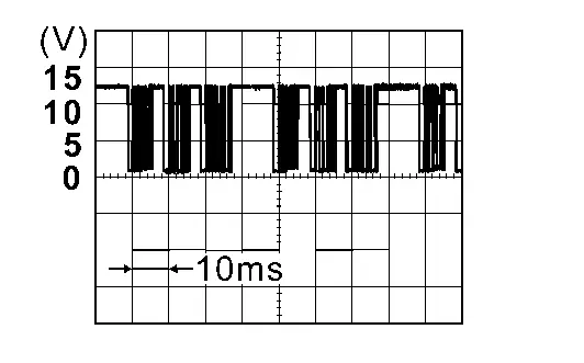
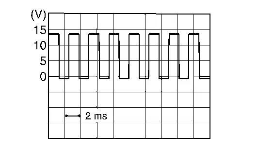
FRONT WIPER CONTROL
The IPDM E/R detects the front wiper stop position from the front wiper auto stop signal.
When front wiper auto stop signal is in the condition listed below while the front wiper is operating, the IPDM E/R activates the fail-safe.
| Ignition switch | Front wiper switch | Front wiper auto stop signal | Fail-safe |
|---|---|---|---|
| ON | OFF | The signal does not change from the battery voltage for 10 seconds. | Stops front wiper power supply for 20 seconds |
| Except OFF | The signal does not change for 10 seconds. |
DTC Inspection Priority Chart
| Priority | DTC No. | CONSULT display | |
|---|---|---|---|
| 1 | U0073-00 | Control module comm Bus A Off | [NO SUBTYPE INFO] |
| U1000-01 | CAN COMM CIRCUIT | [ELECTRICAL MALFUNCTION] | |
| U2004-87 | CAN comm err (CCM/ST angle sensor) | [MISSING MESSAGE] | |
| U2140-87 | CAN comm err (ECM) | [MISSING MESSAGE] | |
| U2141-87 | CAN comm err (TCM) | [MISSING MESSAGE] | |
| U2148-87 | CAN comm err (brake control unit) | [MISSING MESSAGE] | |
| U214E-87 | CAN comm err (combination meter) | [MISSING MESSAGE] | |
| U214F-87 | CAN comm err (BCM) | [MISSING MESSAGE] | |
| U2153-87 | CAN comm err (HVAC) | [MISSING MESSAGE] | |
| U2159-87 | CAN comm err (steering control unit) | [MISSING MESSAGE] | |
| U2176-87 | CAN comm err (CCM/ST angle sensor) | [MISSING MESSAGE] | |
| 2 | B1200-54 | IPDM E/R | [NOT CONFIGURED] |
| B120E-04 | IPDM E/R | [SYSTEM INTERNAL MALFUNCTN] | |
| B120E-42 | IPDM E/R | [MEMORY ERROR] | |
| B120E-51 | IPDM E/R | [SYSTEM INTERNAL MALFUNCTN] | |
| B120E-55 | IPDM E/R | [NOT CONFIGURED] | |
| 3 | B12A3-73 | Fuel pump Off circuit | [CIRC SHORT TO BATTERY] |
| B12A4-81 | Battery current sensor | [INVALID SERIAL DATA RECEIVED] | |
| B12A4-92 | Battery current sensor | [PFM/INCORRECT OPERATN] | |
| B12A4-94 | Battery current sensor | [UNEXPECTED OPERATION] | |
| B20A1-16 | IPDM E/R | [CIRC VOLT BELOW THRESHOLD] | |
| B20A1-72 | IPDM E/R | [ACTUATOR STUCK OPEN] | |
| B20A3-72 | ETC RELAY STUCK ON | [ACTUATOR STUCK OPEN] | |
| B20B2-72 | FRONT WIPER MOTOR CIRCUIT | [ACTUATOR STUCK OPEN] | |
| B20DD-73 | IGN RELAY ON CIRC | [ACTUATOR STUCK CLOSED] | |
| B20DE-72 | IGN RELAY OFF CIRC | [ACTUATOR STUCK OPEN] | |
| 4 | B121A-11 | FR FOG LAMP LH PWR SPLY CIRC | [CIRCUIT SHORT TO GROUND] |
| B121A-15 | FR FOG LAMP LH PWR SPLY CIRC | [CIRC SHORT TO BATT OR OPEN] | |
| B1256-11 | FR FOG LAMP RH PWR SPLY CIRC | [CIRCUIT SHORT TO GROUND] | |
| B1256-15 | FR FOG LAMP RH PWR SPLY CIRC | [CIRC SHORT TO BATT OR OPEN] | |
| B20A2-87 | Headlamp (RH) LIN communication | [MISSING MESSAGE] | |
| B20A4-87 | Headlamp (LH) LIN communication | [MISSING MESSAGE] | |
| B20C7-11 | A/C clutch | [CIRCUIT SHORT TO GROUND] | |
| B20C7-15 | A/C clutch | [CIRC SHORT TO BATT OR OPEN] | |
| B20C8-14 | Compressor (ECV) | [CIRC SHORT TO GRND OR OPEN] | |
| B20D4-11 | TAIL LAMP LH PWR SPLY CIRC | [CIRCUIT SHORT TO GROUND] | |
| B20D5-11 | TAIL LAMP RH PWR SPLY CIRC | [CIRCUIT SHORT TO GROUND] | |
| B20E2-96 | LED HEADLAMP RH | [CMPNENT INTERNAL MLFNCTN] | |
| B20E3-96 | LED HEADLAMP LH | [CMPNENT INTERNAL MLFNCTN] | |
DTC Index
 NOTE:
NOTE:
The details of time display are as follows:
-
CRNT: A malfunction is detected now.
-
PASS: A malfunction was detected in the past.
×: Applicable
| DTC No. | CONSULT display | Fail-safe | Reference | |
|---|---|---|---|---|
| B1200-54 | IPDM E/R | [NOT CONFIGURED] | — | DTC Description |
| B120E-04 | IPDM E/R | [SYSTEM INTERNAL MALFUNCTN] | — | DTC Description |
| B120E-42 | IPDM E/R | [MEMORY ERROR] | — | DTC Description |
| B120E-51 | IPDM E/R | [SYSTEM INTERNAL MALFUNCTN] | — | DTC Description |
| B120E-55 | IPDM E/R | [NOT CONFIGURED] | — | DTC Description |
| B121A-11 | FR FOG LAMP LH PWR SPLY CIRC | [CIRCUIT SHORT TO GROUND] | × | DTC Description |
| B121A-15 | FR FOG LAMP LH PWR SPLY CIRC | [CIRC SHORT TO BATT OR OPEN] | — | DTC Description |
| B1256-11 | FR FOG LAMP RH PWR SPLY CIRC | [CIRCUIT SHORT TO GROUND] | × | DTC Description |
| B1256-15 | FR FOG LAMP RH PWR SPLY CIRC | [CIRC SHORT TO BATT OR OPEN] | — | DTC Description |
| B12A3-73 | Fuel pump Off circuit | [CIRC SHORT TO BATTERY] | — | DTC Description |
| B12A4-81 | Battery current sensor | [INVALID SERIAL DATA RECEIVED] | × | DTC Description |
| B12A4-92 | Battery current sensor | [PFM/INCORRECT OPERATN] | × | DTC Description |
| B12A4-94 | Battery current sensor | [UNEXPECTED OPERATION] | ― | DTC Description |
| B20A1-16 | IPDM E/R | [CIRC VOLT BELOW THRESHOLD] | ― | DTC Description |
| B20A1-72 | IPDM E/R | [ACTUATOR STUCK OPEN] | ― | DTC Description |
| B20A2-87 | Headlamp (RH) LIN communication | [MISSING MESSAGE] | × | DTC Description |
| B20A3-72 | ETC RELAY STUCK ON | [ACTUATOR STUCK OPEN] | — | DTC Description |
| B20A4-87 | Headlamp (LH) LIN communication | [MISSING MESSAGE] | × | DTC Description |
| B20B2-72 | FRONT WIPER MOTOR CIRCUIT | [ACTUATOR STUCK OPEN] | — | DTC Description |
| B20C7-11 | A/C clutch | [CIRCUIT SHORT TO GROUND] | × | DTC Description |
| B20C7-15 | A/C clutch | [CIRC SHORT TO BATT OR OPEN] | × | DTC Description |
| B20D4-11 | TAIL LAMP LH PWR SPLY CIRC | [CIRCUIT SHORT TO GROUND] | × | DTC Description |
| B20D5-11 | TAIL LAMP RH PWR SPLY CIRC | [CIRCUIT SHORT TO GROUND] | × | DTC Description |
| B20DD-73 | IGN RELAY ON CIRC | [ACTUATOR STUCK CLOSED] | × | DTC Description |
| B20DE-72 | IGN RELAY OFF CIRC | [ACTUATOR STUCK OPEN] | × | DTC Description |
| B20E2-96 | LED HEADLAMP RH | [CMPNENT INTERNAL MLFNCTN] | × | DTC Description |
| B20E3-96 | LED HEADLAMP LH | [CMPNENT INTERNAL MLFNCTN] | × | DTC Description |
×: Applicable
| DTC No. | CONSULT display | Fail-safe | Reference | |
|---|---|---|---|---|
| U0073-00 | Control module comm Bus A Off | [NO SUBTYPE INFO] | × | DTC Description |
| U1000-01 | CAN COMM CIRCUIT | [ELECTRICAL MALFUNCTION] | — | DTC Description |
| U2004-87 | CAN comm err (CCM/ST angle sensor) | [MISSING MESSAGE] | — | DTC Description |
| U2140-87 | CAN comm err (ECM) | [MISSING MESSAGE] | × | DTC Description |
| U2141-87 | CAN comm err (TCM) | [MISSING MESSAGE] | — | DTC Description |
| U2148-87 | CAN comm err (brake control unit) | [MISSING MESSAGE] | — | DTC Description |
| U214E-87 | CAN comm err (combination meter) | [MISSING MESSAGE] | — | DTC Description |
| U214F-87 | CAN comm err (BCM) | [MISSING MESSAGE] | × | DTC Description |
| U2153-87 | CAN comm err (HVAC) | [MISSING MESSAGE] | — | DTC Description |
| U2159-87 | CAN comm err (steering control unit) | [MISSING MESSAGE] | — | DTC Description |
| U2176-87 | CAN comm err (CCM/ST angle sensor) | [MISSING MESSAGE] | — | DTC Description |
Removal and Installation. Ipdm E/r (intelligent Power Distribution Module Engine Room) Nissan Pathfinder
Removal and Installation
CAUTION:
IPDM E/R integrated relays are not serviceable parts and must not be removed from the unit.
REMOVAL
Disconnect the negative battery terminal. Refer to Battery Disconnect.
Release the pawls and separate the IPDM E/R (1) from the case.
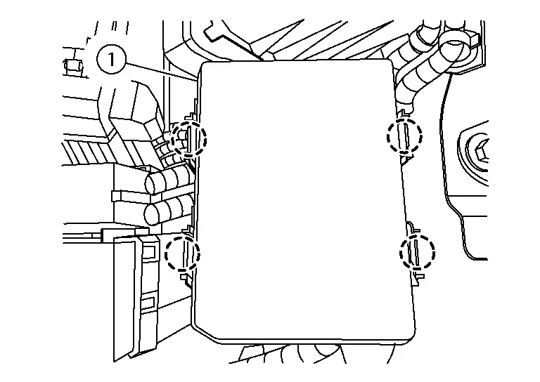
 |
: Pawl |
Disconnect the harness connectors (A) from the IPDM E/R (1).
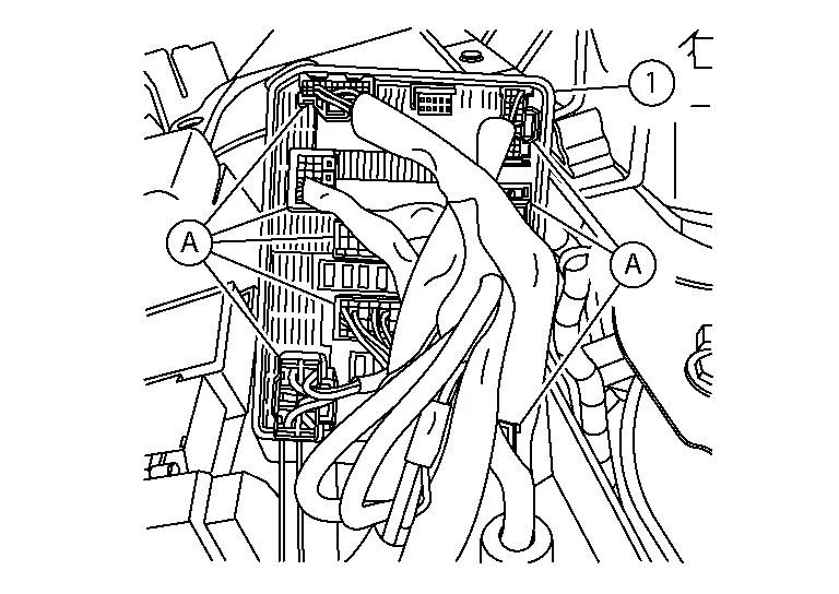
Remove the IPDM E/R.
INSTALLATION
Installation is in the reverse order of removal.
CAUTION:
If replacing IPDM E/R, perform "ADDITIONAL SERVICE WHEN REPLACING IPDM E/R". Refer to Work Procedure.

Nissan Pathfinder (R53) 2022-2026 Service Manual
Ipdm E/r
- Precautions
- Ecu Diagnosis Information. Ipdm E/r
- Removal and Installation. Ipdm E/r (intelligent Power Distribution Module Engine Room)
Contact Us
Nissan Pathfinder Info Center
Email: info@nipathfinder.com
Phone: +1 (800) 123-4567
Address: 123 Pathfinder Blvd, Nashville, TN 37214, USA
Working Hours: Mon–Fri, 9:00 AM – 5:00 PM (EST)
