Nissan Pathfinder: System (intelligent Key System) - Information Display (combination Meter) ++
Door Open Warning
DESIGN/PURPOSE
Information display warns the driver that each door is open or is not fully closed.
| Symbol | Message |
|---|---|
|
|
– |
SYSTEM DIAGRAM
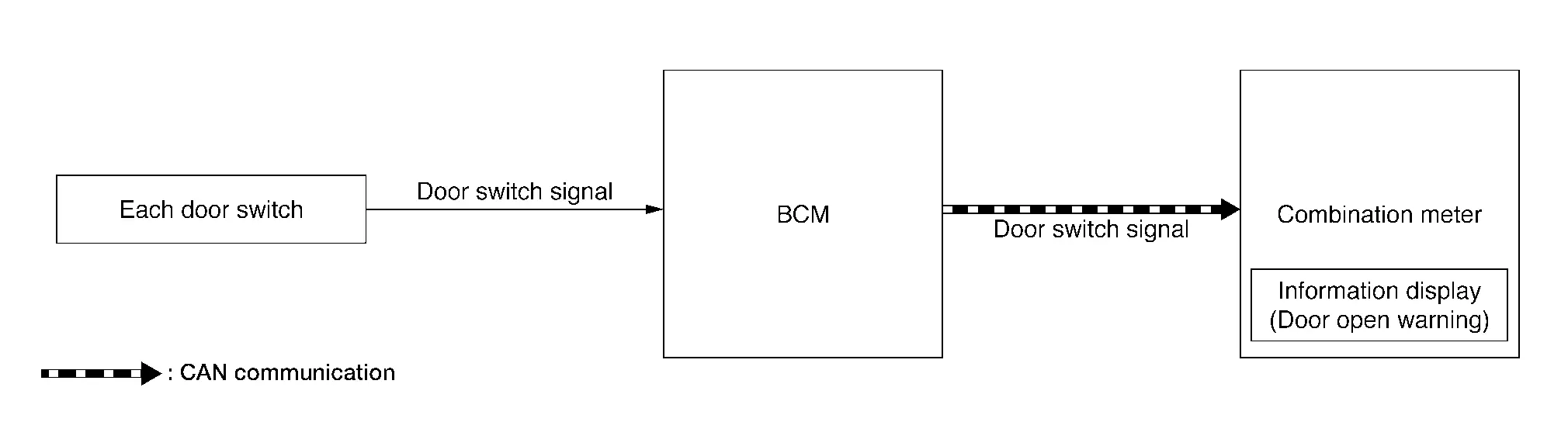
Signal transmission function list
| Signal name | Input | Output | Description |
|---|---|---|---|
| Door switch signal | Door switch | BCM | Inputs door switch signal and transmits it via CAN communication. |
| BCM | Combination meter |
SIGNAL PATH
-
BCM transmits door switch signal to combination meter via CAN communication.
-
When combination meter judges according to received door switch signal that a door is open or not fully closed, door open warning displays.
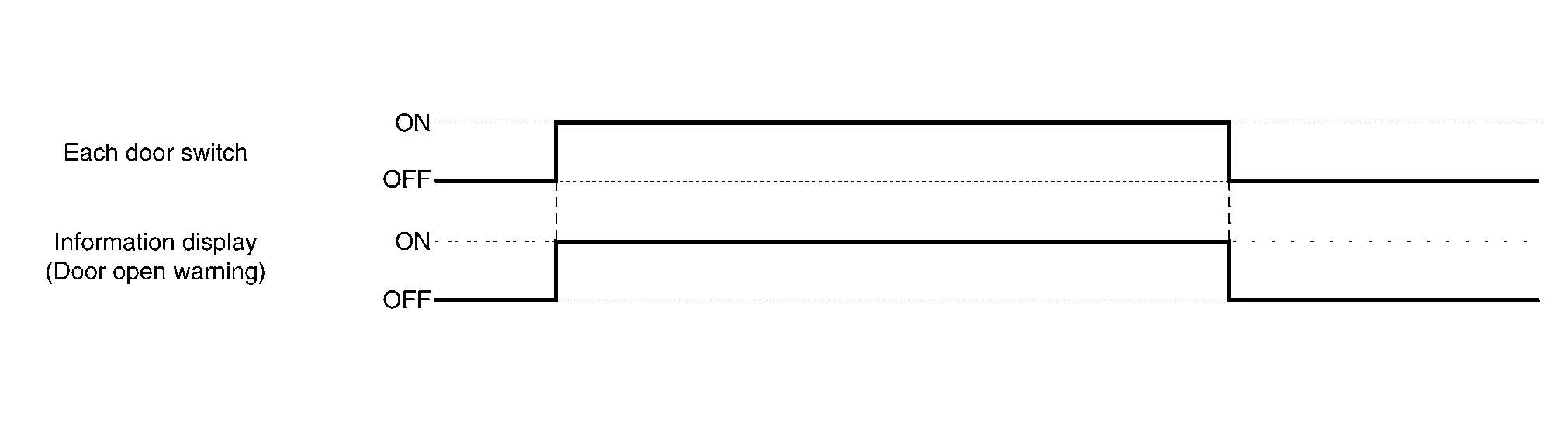
WARNING/INDICATOR OPERATIONG CONDITION
Each door switch is ON
WARNING/INDICATOR CANCEL CONDITION
All door switches are OFF
TIMING CHART
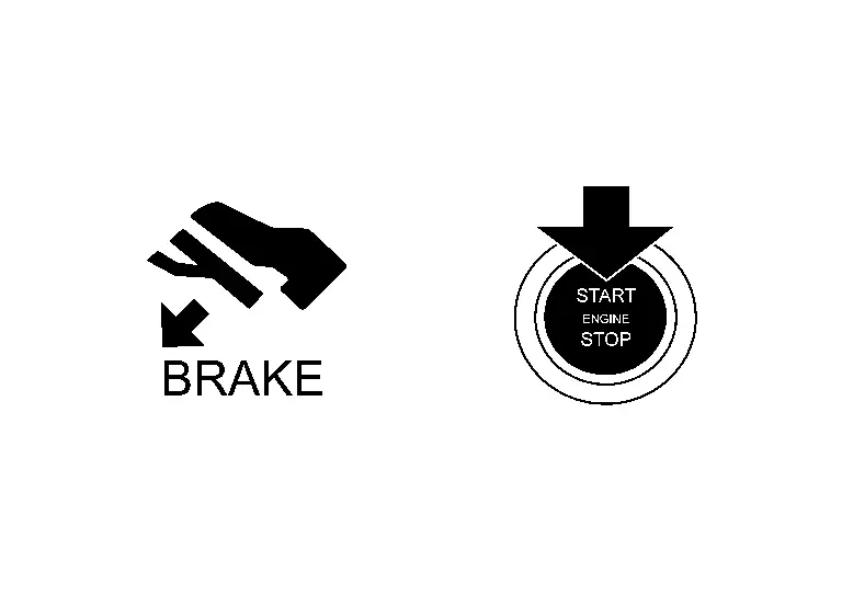
Engine Start Information
DESIGN/PURPOSE
Information display informs the driver that the engine can be started.
| Symbol | Message | |
|---|---|---|
|
|
Push brake and start switch to drive | |
SYNCHRONIZATION WITH MASTER WARNING LAMP
No applicable
SYSTEM DIAGRAM
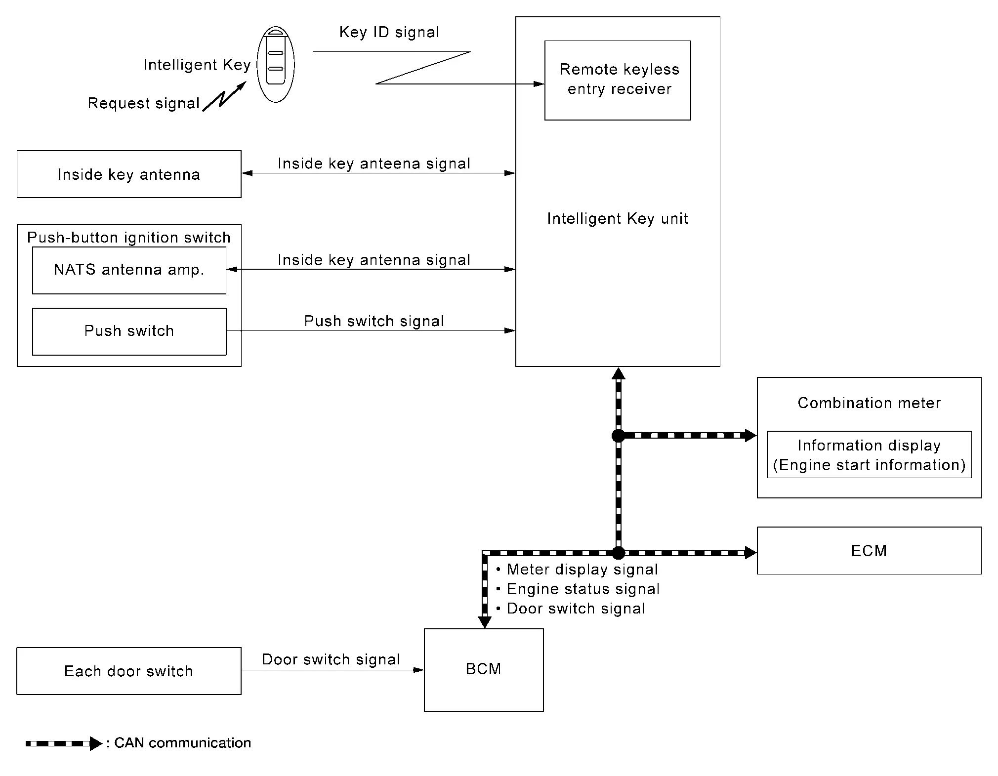
Signal transmission function list
| Signal name | Input | Output | Description |
|---|---|---|---|
| Key ID signal | Remote keyless entry receiver | Intelligent Key Unit | Inputs Key ID signal to the Intelligent Key Unit to activate/deactivate each door lock actuator. |
| Inside key antenna signal | Inside key antenna | Intelligent Key Unit | Inputs inside key antenna signal. |
| NATS antenna amp. (push-button ignition switch) | Intelligent Key Unit | Inputs inside key antenna signal. | |
| Push switch signal | Push-button ignition switch | Intelligent Key Unit | Inputs push-button ignition switch signal. |
| Door switch signal | Door switch | BCM | Inputs door switch signal. |
| BCM | Intelligent Key Unit | Inputs door switch signal and transmits it via CAN communication. | |
| Meter display signal | BCM | Combination meter | Inputs Meter display signal to the combination meter to display engine start information. |
| Engine status signal | Intelligent Key Unit | ECM | Inputs engine status signal and transmits it via CAN communication. |
SIGNAL PATH
-
Intelligent Key unit receives engine status signal from ECM via CAN communication and checks that the engine can be started.
-
When Intelligent Key unit detects that the engine can be started, meter display signal is transmitted by Intelligent Key unit to combination meter via CAN communication.
-
When combination meter receives meter display signal, engine start information displays.
WARNING/INDICATOR OPERATION CONDITION
When Ignition Switch is ON.
When all of the following conditions are satisfied:
-
Ignition switch is in ON position.
-
Shift position: P position.
-
Engine can be started.
When Ignition Switch is Other Than ON.
When all of the following conditions are satisfied:
-
One condition of A
-
All conditions of B
A condition B condition -
Any door is open → All door is closed
-
Push-button ignition switch: Pressed
-
Intelligent Key backside is contacted to push-button ignition switch while brake pedal is depressed.
-
Ignition switch: OFF position
-
Shift position: P position
-
Registered Intelligent Key is detected inside Nissan Pathfinder vehicle.
-
WARNING/INDICATOR CANCEL CONDITION
When Ignition Switch is ON.
When any of the following conditions are satisfied:
-
Engine is started.
-
Shift position: Other than P position.
When Ignition Switch is Other than ON.
When any of the following conditions are satisfied:
-
Shift position: Other than P position.
-
Registered Intelligent Key is not detected inside the Nissan Pathfinder vehicle.
-
When Intelligent Key unit receives Intelligent Key button operation via remote keyless entry receiver.
-
When Intelligent Key unit receives door request switch signal from door request switch.
-
After 15 seconds are passed since the engine start information is displayed.
Intelligent Key Low Battery Warning
DESIGN/PURPOSE
Information display warns the driver that Intelligent Key battery level is low.
 NOTE:
NOTE:
Information display does not display when Intelligent Key battery is discharged.
| Symbol | Message |
|---|---|
|
|
Key Battery Low |
SYNCHRONIZATION WITH MASTER WARNING LAMP
No applicable
SYSTEM DIAGRAM
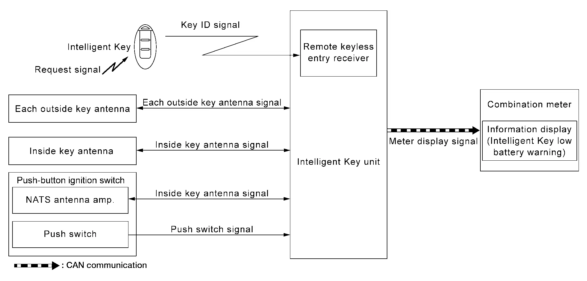
Signal transmission function list
| Signal name | Input | Output | Description |
|---|---|---|---|
| Key ID signal | Remote keyless entry receiver | Intelligent Key Unit | Inputs Key ID signal to the Intelligent Key Unit to activate/deactivate each door lock actuator. |
| Outside key antenna signal | Outside key antenna | Intelligent Key Unit | Inputs outside key antenna signal. |
| Inside key antenna signal | Inside key antenna | Intelligent Key Unit | Inputs inside key antenna signal. |
| NATS antenna amp. (push-button ignition switch) | Intelligent Key Unit | Inputs inside key antenna signal. | |
| Push switch signal | Push-button ignition switch | Intelligent Key Unit | Inputs push-button ignition switch signa. |
| Meter display signal | Intelligent Key Unit | Combination meter | Inputs Meter display signal to the combination meter via CAN communication to display Intelligent Key low battery warning. |
SIGNAL PATH
-
When Intelligent Key receives a request signal from inside key antenna or outside key antenna, transmits key ID signal is transmitted from Intelligent Key to Intelligent Key unit.
-
Intelligent Key unit receives key ID signal via remote keyless entry receiver and detects that Intelligent Key battery level is low.
-
When Intelligent Key unit detects that ignition switch is ON, meter display signal is transmitted by Intelligent Key unit to combination meter via CAN communication.
-
When combination meter receives meter display signal, Intelligent Key low battery warning displays.
SIGNAL PATH
-
When Intelligent Key receives request signal from inside key antenna or outside key antenna, transmits key ID signal is transmitted from Intelligent Key to Intelligent Key unit.
-
Intelligent Key unit receives key ID signal via remote keyless entry receiver and detects that Intelligent Key battery level is low.
-
When Intelligent Key unit detects that ignition switch is ON, meter display signal is transmitted by Intelligent Key unit to combination meter via CAN communication.
-
When combination meter receives meter display signal, Intelligent Key low battery warning displays.
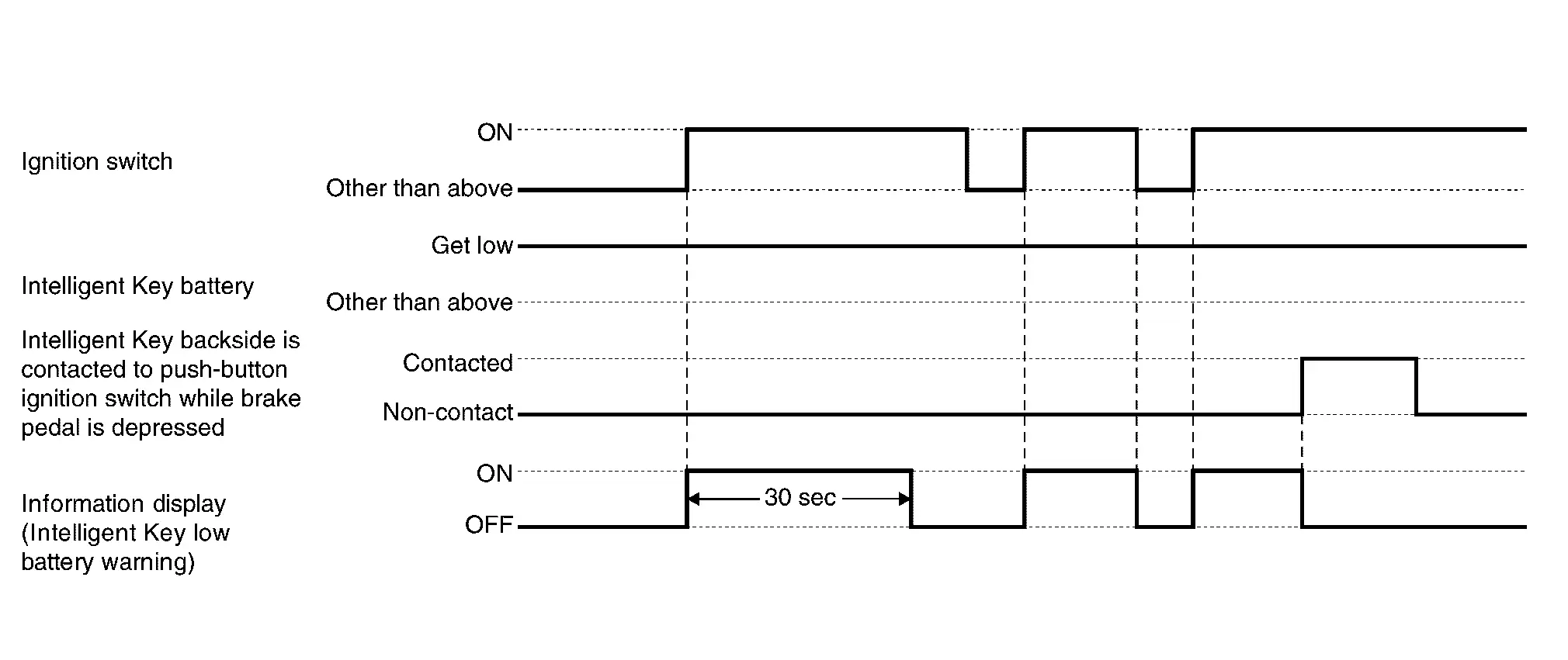
WARNING/INDICATOR OPERATING CONDITION
When all of the following conditions are satisfied:
-
Ignition switch is in ON position.
-
Intelligent Key battery level is low.
WARNING/INDICATOR CANCEL CONDITION
When any of the following conditions are satisfied:
-
After 30 seconds are passed since the Intelligent Key low battery warning is displayed.
-
Ignition switch is in a position other than ON.
-
When Intelligent Key backside is contacted to push-button ignition switch while brake pedal is depressed.
TIMING CHART
Intelligent Key System Malfunction
DESIGN/PURPOSE
Information display warns the driver that Intelligent Key system malfunctions or that engine cannot be started.
| Symbol | Message |
|---|---|
|
|
Key System Error See Owner’s Manual |

SYSTEM DIAGRAM
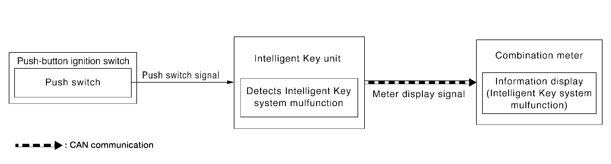
Signal transmission function list
| Signal name | Input | Output | Description |
|---|---|---|---|
| Push switch signal | Door switch | Intelligent Key Unit | Inputs push-button ignition switch signal. |
| Meter display signal | Intelligent Key Unit | Combination meter | Inputs Meter display signal to the combination meter via CAN communication to display Intelligent Key system malfunction. |
SIGNAL PATH
-
When Intelligent Key unit detects that Intelligent Key system malfunctions or that the engine cannot be started, meter display signal is transmitted by Intelligent Key unit to combination meter via CAN communication.
-
When combination meter receives meter display signal, Intelligent Key system malfunction displays.
WARNING/INDICATOR OPERATING CONDITION
When any of the following conditions are satisfied:
-
The engine cannot be started.
-
Intelligent Key system malfunction is detected.
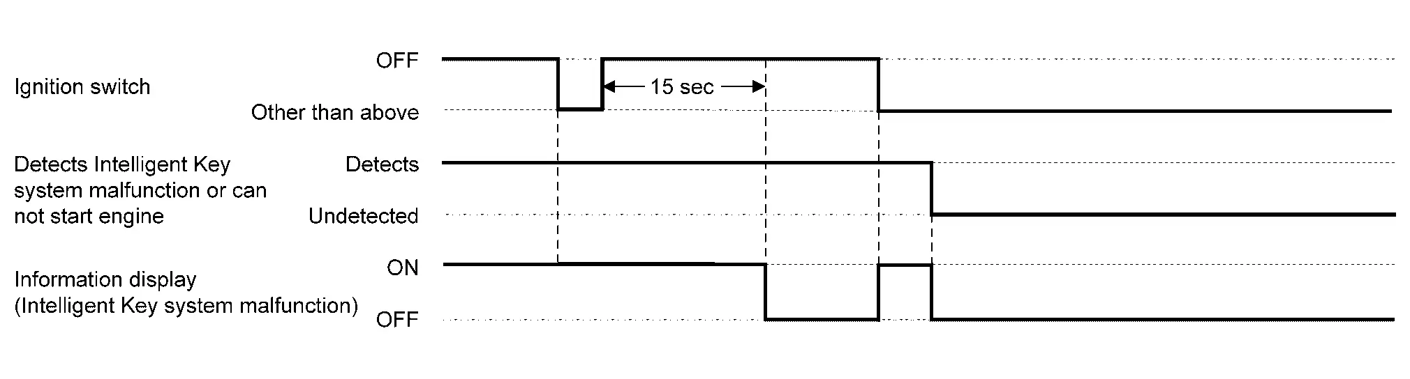
WARNING/INDICATOR CANCEL CONDITION
When any of the following conditions are satisfied:
-
Intelligent Key system malfunction or engine non-start status is resolved.
-
Ignition switch is turned to OFF, and 15 seconds are passed.
TIMING CHART
Key ID Verification Information
DESIGN/PURPOSE
If the system cannot detect a registered Intelligent Key inside the vehicle, it informs the driver that it is necessary for the Nissan Pathfinder vehicle to detect a registered Intelligent Key.
| Symbol | Message |
|---|---|
|
|
– |
SYNCHRONIZATION WITH MASTER WARNING LAMP
No applicable
SYSTEM DIAGRAM
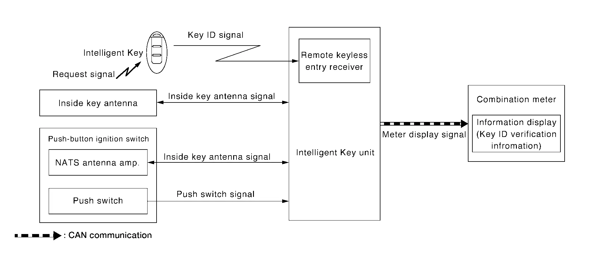
Signal transmission function list
| Signal name | Input | Output | Description |
|---|---|---|---|
| Key ID signal | Remote keyless entry receiver | Intelligent Key Unit | Inputs Key ID signal to the Intelligent Key Unit to activate/deactivate each door lock actuator. |
| Inside key antenna signal | Inside key antenna | Intelligent Key Unit | Inputs inside key antenna signal. |
| NATS antenna amp. (push-button ignition switch) | Intelligent Key Unit | Inputs inside key antenna signal. | |
| Push switch signal | Push-button ignition switch | Intelligent Key Unit | Inputs push-button ignition switch signal. |
| Meter display signal | BCM | Combination meter | Inputs Meter display signal to the combination meter via CAN communication to display Key ID verification information. |
SIGNAL PATH
-
Intelligent Key unit activates inside key antenna and checks that Intelligent Key is in vehicle, when push-button ignition switch operation is performed while ignition switch position is OFF.
-
When Intelligent Key unit does not detect a registered Intelligent Key in Nissan Pathfinder vehicle, meter display signal is transmitted by Intelligent Key unit to combination meter via CAN communication.
-
When combination meter receives meter display signal, key ID verification information displays.
WARNING/INDICATOR OPERATION CONDITION
When all of the following conditions are satisfied:
-
Ignition switch is OFF position.
-
Push-button ignition switch operation is performed.
-
Registered Intelligent Key is not detected inside the Nissan Pathfinder vehicle.
WARNING/INDICATOR CANCEL CONDITION
When any of the following conditions are satisfied:
-
After 5 seconds are passed since the key ID verification information is displayed.
-
When Intelligent Key backside is contacted to push-button ignition switch while brake pedal is depressed. And then place ignition switch ON.
-
Registered Intelligent Key is detected inside the Nissan Pathfinder vehicle.
Take Away Warning (Information Display)
DESIGN/PURPOSE
Information display warns the driver that Intelligent Key is not detected in vehicle.
| Symbol | Message |
|---|---|
|
|
No Key Detected |

SYSTEM DIAGRAM
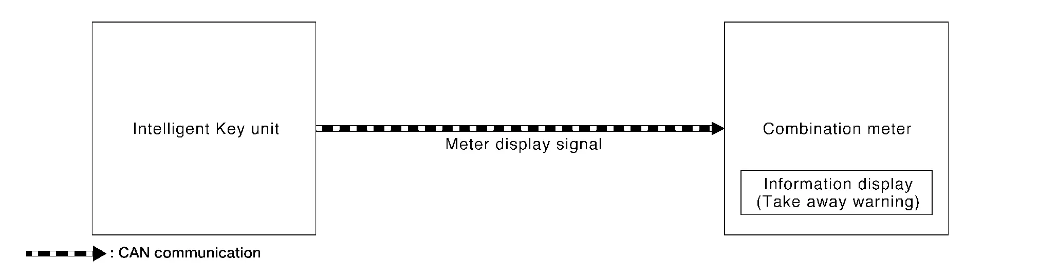
Signal transmission function table
| Signal name | Input | Output | Description |
|---|---|---|---|
| Key ID signal | Intelligent Key Unit | Combination meter | Inputs Meter display signal to the combination meter via CAN communication to display Take away warning information. |
SIGNAL PATH
-
Intelligent Key unit transmits meter display signal to combination meter via CAN communication, when take away warning (buzzer) is operated.
-
When combination meter receives meter display signal, take away warning displays.
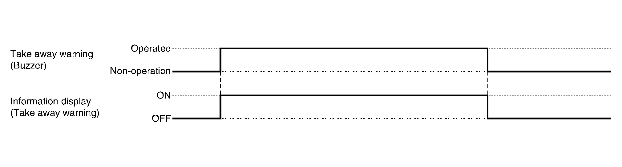
TIMING CHART

Nissan Pathfinder (R53) 2022-2026 Service Manual
Contact Us
Nissan Pathfinder Info Center
Email: info@nipathfinder.com
Phone: +1 (800) 123-4567
Address: 123 Pathfinder Blvd, Nashville, TN 37214, USA
Working Hours: Mon–Fri, 9:00 AM – 5:00 PM (EST)
