Nissan Pathfinder: Power Window Control System - Ecu Diagnosis Information
Nissan Pathfinder (R53) 2022-2026 Service Manual / Body Exterior, Doors, Roof & Vehicle Security :: Power Window Control System / Ecu Diagnosis Information
Bcm Nissan Pathfinder R53
List of ECU Reference
| ECU | Reference |
|---|---|
| BCM | Values on the Diagnosis Tool |
| Reference Value | |
| Fail-safe | |
| DTC Inspection Priority Chart | |
| DTC Index |
Main Power Window and Door Mirror Switch Nissan Pathfinder SUV
Reference Value
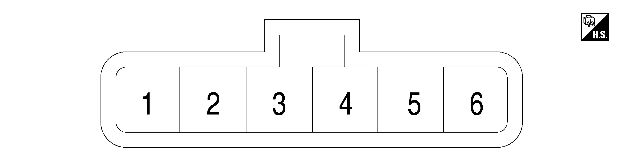
TERMINAL LAYOUT

PHYSICAL VALUES
|
Terminal No. (Wire color) | Description | Condition |
Value (Approx.) | |||
|---|---|---|---|---|---|---|
| + | – | Signal name | Input/Output | |||
|
1 (G) |
Ground | Front LH UP signal | Output | Front power window motor LH | Operate (UP) | Battery voltage |
| Other than above | 0 V | |||||
|
2 (BG) |
Ground | Down mirror motor sensor power supply | Output | — | 5 V | |
|
3 (BR) |
Ground | Auto ACC power supply | Input | Ignition switch OFF (auto ACC status) or ON | Battery voltage | |
|
4 (W) |
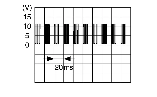
Ground | LIN communication signal | Input/ Output | Ignition switch ON |
|
|
|
6 (V) |
Ground | Door mirror motor LH UP output signal | Output | Door mirror LH | Operate (UP) | Battery voltage |
| Other than above | 0 - 1 V | |||||
|
7 (LG)1 (LA/G)2 |
Ground | Door mirror sensor LH UP/DOWN signal1 | Output | Door mirror LH position | Change between 5 V (close to peak) - 2 V (close to valley) | |
| Door mirror motor RH DOWN/RIGHT output signal2 | Door mirror RH position | Operate (DOWN/RIGHT) | Battery voltage | |||
| Other than above | 0 - 1 V | |||||
|
8 (P)1 (LA/L)2 |
Ground | Door mirror sensor LH LEFT/RIGHT signal1 | Output | Door mirror LH position | 3 V | |
| Door mirror motor RH UP output signal2 | Door mirror RH position | Operate (UP) | Battery voltage | |||
| Other than above | 0 - 1 V | |||||
|
92 (LA/Y) |
Ground | Door mirror motor RH LEFT output signal | Output | Door mirror RH | Operate (LEFT) | Battery voltage |
| Other than above | 0 V | |||||
|
10 (Y) |
Ground | Door mirror motor LH LEFT output signal | Output | Door mirror LH | Operate (LEFT) | Battery voltage |
| Other than above | 0 V | |||||
|
13 (L) |
Ground | Front LH DOWN signal | Output | Front power window motor LH | Operate (AUTO DOWN) | Battery voltage |
| Other than above | 0 V | |||||
|
14 (Y) |
Ground | Ground (door mirror sensor) | — | — | 0 V | |
|
17 (SB) |
Ground | Door mirror LH power fold motor OPEN output signal | Output | Door mirror LH | Operate (OPEN) | Battery voltage |
| Other than above | 0 V | |||||
|
18 (R) |
Ground | Door mirror LH power fold motor CLOSE output signal | Output | Door mirror LH | Operate (CLOSE) | Battery voltage |
| Other than above | 0 V | |||||
|
19 (GR) |
Ground | Door mirror RH power fold motor OPEN output signal | Output | Door mirror RH | Operate (OPEN) | Battery voltage |
| Other than above | 0 V | |||||
|
20 (G) |
Ground | Door mirror RH power fold motor CLOSE output signal | Output | Door mirror RH | Operate (CLOSE) | Battery voltage |
| Other than above | 0 V | |||||
|
21 (L) |
Ground | Door mirror motor LH DOWN/RIGHT output signal | Output | Door mirror LH | Operate (DOWN/RIGHT) | Battery voltage |
| Other than above | 0 V | |||||
|
22 (B) |
Ground | Ground | — | — | 0 V | |

1 : With automatic drive positioner
2 : Without automatic drive positioner
Front Power Window Motor Lh Nissan Pathfinder R53
Reference Value
TERMINAL LAYOUT

PHYSICAL VALUES
|
Terminal No. (Wire color) | Description | Condition |
Value (Approx.) | ||
|---|---|---|---|---|---|
| + | – | Signal name | Input/Output | ||
|
1 (L) |
Ground | Front power window motor LH DOWN signal | Input | Ignition switch OFF (auto ACC status) or ON | Battery voltage |
| Ignition switch OFF (not auto ACC status) | 0 V | ||||
|
2 (G) |
Ground | Front power window motor LH UP signal | Input | Ignition switch OFF (auto ACC status) or ON | Battery voltage |
| Ignition switch OFF (not auto ACC status) | 0 V | ||||
|
3 (B) |
Ground | Ground | — | — | 0 V |
|
4 (LG) |
Ground | Auto ACC power supply | Input | Ignition switch OFF (auto ACC status) or ON | Battery voltage |
| Ignition switch OFF (not auto ACC status) | 0 V | ||||
|
6 (W) |
Ground | LIN communication signal | Input/Output | Ignition switch ON |
|
FailSafe
FAIL-SAFE CONTROL BY POWER WINDOW MOTOR
Power window motor switches power window operation to fail-safe control when malfunction is detected.
| Detected item | Judgment condition | Fail-safe operation | Recovery condition |
|---|---|---|---|
| Non-Initialized condition | When the motor integrated CPU detect door glass position non-initialized condition | Auto UP operation (Anti-pinch) is forbidden | Initialization completed |
| Thermal protection | When the motor integrated CPU first detects thermal protection | DOWN operation is forbidden |
After cooling, a certain amount of time has passed in the ignition switch ON state. (Reference values: approximately 30 to 90 seconds, the elapsed time will be changed depending on how the temperature drops.) |
| When the motor integrated CPU detects thermal protection again when UP is operated from the above state | Operation is forbidden (UP and DOWN is forbidden | ||
| Consecutive reverse operation malfunction | When the motor integrated CPU has detected consecutively 3 times the reverse operation | Auto UP operation (Anti-pinch) is forbidden | Approximately 10 seconds passed or the motor integrated CPU detect door glass fully close position |
Rear Power Window Motor Lh Nissan Pathfinder R53
Reference Value
TERMINAL LAYOUT
PHYSICAL VALUES
|
Terminal No. (Wire color) | Description | Condition |
Value (Approx.) | ||
|---|---|---|---|---|---|
| + | – | Signal name | Input/Output | ||
|
1 (Y) |
Ground | Rear power window motor LH DOWN signal | Input | Ignition switch OFF (auto ACC status) or ON | Battery voltage |
| Ignition switch OFF (not auto ACC status) | 0 V | ||||
|
2 (R) |
Ground | Rear power window motor LH UP signal | Input | Ignition switch OFF (auto ACC status) or ON | Battery voltage |
| Ignition switch OFF (not auto ACC status) | 0 V | ||||
|
3 (B) |
Ground | Ground | — | — | 0 V |
|
4 (V) |
Ground | Auto ACC power supply | Input | Ignition switch OFF (auto ACC status) or ON | Battery voltage |
| Ignition switch OFF (not auto ACC status) | 0 V | ||||
|
6 (LG) |
Ground | LIN communication signal | Input/Output | Ignition switch ON |
|


Nissan Pathfinder (R53) 2022-2026 Service Manual
Ecu Diagnosis Information
Contact Us
Nissan Pathfinder Info Center
Email: info@nipathfinder.com
Phone: +1 (800) 123-4567
Address: 123 Pathfinder Blvd, Nashville, TN 37214, USA
Working Hours: Mon–Fri, 9:00 AM – 5:00 PM (EST)
