Nissan Pathfinder: Charging System - Dtc/circuit Diagnosis
- B12a4-81 Battery Current Sensor
- Charging System Preliminary Inspection
- Power Generation Voltage Variable Control System Operation Inspection
- B Terminal Circuit
B12a4-81 Battery Current Sensor Nissan Pathfinder R53
DTC Description
DTC DETECTION LOGIC
| DTC No. | CONSULT screen items | DTC Detection Condition | ||
|---|---|---|---|---|
| (Trouble diagnosis content) | [Malfunction type] | |||
| B12A4–81 |
Battery current sensor (Battery current sensor) |
[INVALID SERIAL DATA RECEIVED] | Diagnosis condition | When ignition switch is ON. |
| Signal (terminal) | LIN (BAT CURRENT SEN) | |||
| Threshold | Battery current sensor and IPDM E/R cannot communicate with LIN communication signal. | |||
| Diagnosis delay time | 2 seconds or more | |||
POSSIBLE CAUSE
-
Battery terminal is not connected
-
Harness or connectors
-
IPDM E/R
FAIL-SAFE
Fix the power generation command value to 14.3 V.
DTC CONFIRMATION PROCEDURE
PERFORM COMPONENT FUNCTION CHECK
 CONSULT
-
Start engine and wait for 10 seconds or more.
-
Select “Self Diagnostic Result” mode of “IPDM E/R”.
Is the inspection result normal?
YES>>To check malfunction symptom before repair: Refer to Intermittent Incident.
YES>>Confirmation after repair: Inspection End.
NO>>Refer to DTC Diagnosis Procedure.
DTC Diagnosis Procedure
CHECK LIN COMMUNICATION SIGNAL 1
 CONSULT
Select “Battery current sen value (LIN)” in “Data Monitor” mode of “IPDM E/R”.
| Monitor item | Condition | Monitor status |
|---|---|---|
| Battery current sen value (LIN) |
Engine running
|
(–200.00) – (+300.00) A |
Is the inspection result normal?
YES>>GO TO 2.
NO>>Replace IPDM E/R. Refer to Removal and Installation.
CHECK FUSE
-
Ignition switch OFF.
-
Check that the following fuse is not blown (open):
No. Capacity 101 10 A
Is the fuse blown (open)?
YES>>Replace the blown (open) fuse after repairing the cause of blown (open).
NO>>GO TO 3.
CHECK 12V BATTERY CURRENT SENSOR POWER
-
Disconnect battery current sensor connector.
-
Ignition switch ON.
-
Check the voltage between battery current sensor harness connector and ground.
(+) (—) Voltage
(Approx.)Battery current sensor Connector Terminal E47 1 Ground Battery voltage
Is the inspection result normal?
YES>>GO TO 4.
NO>>Repair or replace harness.
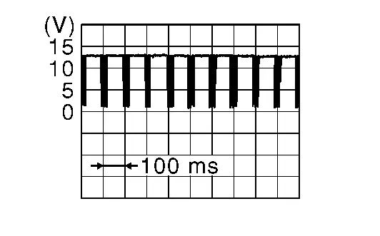
CHECK LIN COMMUNICATION SIGNAL 2
Check signal between battery current sensor harness connector and ground using an oscilloscope.
| (+) | (—) | Signal | |
|---|---|---|---|
| Battery current sensor | |||
| Connector | Terminal | ||
| E47 | 2 | Ground |
|
Is the inspection result normal?
YES>>Repair or replace harness.
NO>>Replace battery current sensor.
Charging System Preliminary Inspection Nissan Pathfinder
Diagnosis Procedure
CHECK BATTERY TERMINALS CONNECTION
Check if battery terminals are clean and tight.
Is the inspection result normal?
YES>>GO TO 2.
NO>>Repair battery terminal connection. Confirm repair by performing system test using 165-DSS-5000P. Refer to the applicable instruction manual for proper testing procedures.
CHECK FUSE
Check for blown fuse and fusible link:
| Unit | Power source (Power supply terminals) | Fuse or Fusible Link No. | Capacity |
|---|---|---|---|
| Generator | Battery (terminal 1) | Fusible Link A | 450 A |
| Battery current sensor | Battery (terminal 1) | Fuse 101 | 10 A |
| Combination meter | Battery (terminal 5) | Fuse 29 | 10 A |
| Ignition switch ON (terminal 6) | Fuse 6 | 10 A |
Is the inspection result normal?
YES>>GO TO 3.
NO>>Replace the blown fuse or fusible link after repairing the affected circuit.
CHECK DRIVE BELT TENSION
Check drive belt tension. Refer to Checking Drive Belt.
Is the inspection result normal?
YES>>Inspection End.
NO>>Repair as needed.
Power Generation Voltage Variable Control System Operation Inspection Nissan Pathfinder 2022
Diagnosis Procedure
CAUTION:
When performing this inspection, always use a charged battery that has completed the battery inspection. (When the charging rate of the battery is low, the response speed of the voltage change will become slow. This can cause an incorrect inspection.)
CHECK ECM
 CONSULT
Select “Self Diagnostic Result” mode of “ENGINE”. Refer to CONSULT Function.
Self-diagnostic results content
No malfunction detected>>GO TO 2.
Malfunction detected>>Check applicable parts, and repair or replace corresponding parts. Refer to DTC Index.
CHECK HARNESS BETWEEN GENERATOR AND ECM
-
Ignition switch OFF.
-
Disconnect generator connector and ECM connector.
-
Check continuity between generator harness connector and ECM harness connector.
Generator ECM Continuity Connector Terminal Connector Terminal F7 2 F79 167 Yes -
Check continuity between generator harness connector and ground.
Generator — Continuity Connector Terminal F7 2 Ground No
Is the inspection result normal?
YES>>Replace ECM. Refer to Removal and Installation.
NO>>Repair harness or connectors between ECM and generator.
B Terminal Circuit Nissan Pathfinder
Description
“B” terminal circuit supplies power to charge the battery and to operate the vehicles electrical system.
Diagnosis Procedure
CHECK “B” TERMINAL CONNECTION
-
Ignition switch OFF.
-
Check if “B” terminal is clean and tight.
Is the inspection result normal?
YES>>GO TO 2.
NO>>Repair terminal “B” connection. Confirm repair by performing system test using 165-DSS-5000P. Refer to applicable instruction manual for proper testing procedures.
CHECK “B” TERMINAL CIRCUIT
Check voltage between generator “B” terminal and ground.
| (+) | (—) |
Voltage (Approx.) | |
|---|---|---|---|
| Generator | |||
| Connector | Terminal | ||
| F6 | 1 | Ground | Battery voltage |
Is the inspection result normal?
YES>>GO TO 3.
NO>>Check harness for open between generator and fusible link.
CHECK “B” TERMINAL CONNECTION (VOLTAGE DROP TEST)
-
Start engine, then engine running at idle and warm.
-
Check voltage between battery positive terminal and generator connector “B” terminal.
(+) (—) Voltage
(Approx.)Generator Connector Terminal F6 1 Battery positive terminal Less than 0.2 V
Is the inspection result normal?
YES>>“B” terminal circuit is normal. Refer to Work Flow (With 165-DSS-5000P) or Work Flow (Without 165-DSS-5000P).
NO>>Check harness between battery and generator for continuity.

Nissan Pathfinder (R53) 2022-2026 Service Manual
Dtc/circuit Diagnosis
- B12a4-81 Battery Current Sensor
- Charging System Preliminary Inspection
- Power Generation Voltage Variable Control System Operation Inspection
- B Terminal Circuit
Contact Us
Nissan Pathfinder Info Center
Email: info@nipathfinder.com
Phone: +1 (800) 123-4567
Address: 123 Pathfinder Blvd, Nashville, TN 37214, USA
Working Hours: Mon–Fri, 9:00 AM – 5:00 PM (EST)
