Nissan Pathfinder: Wiper & Washer - Dtc/circuit Diagnosis
- B20b2-72 Front Wiper Motor Circuit
- B2cb4-49 Rain Sensor
- B2cb5-64 Rear Wiper
- Front Wiper Motor Lo Circuit
- Front Wiper Auto Stop Position Signal Circuit
- Front Wiper Motor Ground Circuit
- Rear Wiper Motor Circuit
- Rear Wiper Stop Position Signal Circuit
- Washer Switch Circuit
- Washer Switch
- Rain Sensor
B20b2-72 Front Wiper Motor Circuit Nissan Pathfinder 2022
DTC Description
DTC DETECTION LOGIC
| DTC No. |
CONSULT display description (Trouble diagnosis content) | DTC detection condition | ||
|---|---|---|---|---|
| B20B2–72 | Front wiper motor circuit | [ACTUATOR STUCK OPEN] | Diagnosis condition | Ignition switch is ON. |
| Signal (terminal) | Monitors the status of front wiper relay side with CPU of IPDM E/R. | |||
| Threshold | Detection of front wiper relay OFF. | |||
| Diagnosis delay time | 1 second or more. | |||
POSSIBLE CAUSE
-
Harness or connector
(The front wiper motor circuit is open or shorted)
-
IPDM E/R
FAIL-SAFE
—
DTC CONFIRMATION PROCEDURE
DTC CONFIRMATION
 CONSULT
-
Ignition switch ON.
-
Select “Self Diagnostic Result” mode of “IPDM E/R”.
Is any DTC detected?
YES>>Refer to DTC Diagnosis Procedure.
NO>>To check malfunction symptom before repair: Refer to Intermittent Incident.
NO>>Confirmation after repair: Inspection End.
DTC Diagnosis Procedure
CHECK FUSE
-
Ignition switch OFF.
-
Check that the following fuse is not blown (open):
| Signal name | Fuse No. | Capacity |
|---|---|---|
| Battery voltage | 77 | 30 A |
Is the fuse blown (open)?
YES>>Replace the blown fuse after repairing the affected circuit.
NO>>GO TO 2.
CHECK IPDM E/R POWER SUPPLY AND GROUND CIRCUIT
Check IPDM E/R power supply and ground circuit. Refer to Diagnosis Procedure.
Is the inspection result normal?
YES>>GO TO 3.
NO>>Repair or replace malfunctioning part.
REPLACE IPDM E/R
Replace IPDM E/R. Refer to Removal and Installation.
>>
Inspection End.
B2cb4-49 Rain Sensor Nissan Pathfinder SUV
DTC Description
DTC DETECTION LOGIC
| DTC No. |
CONSULT screen terms (Trouble diagnosis content) | DTC detection condition | |
|---|---|---|---|
| B2CB4–49 |
Rain sensor (Rain sensor) |
Diagnosis condition | Ignition switch is ON. |
| Signal (terminal) | — | ||
| Threshold | Rain sensor internal malfunction. | ||
| Diagnosis delay time | 2 seconds or more | ||
POSSIBLE CAUSE
Rain sensor
FAIL SAFE
—
DTC CONFIRMATION PROCEDURE
PERFORM DTC CONFIRMATION PROCEDURE
 CONSULT
-
Ignition switch ON.
-
Select “Self Diagnostic Result” mode of “BCM”.
-
Check DTC.
Is DTC detected?
YES>>Refer to DTC Diagnosis Procedure.
NO>>To check malfunction symptom before repair: Refer to Intermittent Incident.
NO>>Confirmation after repair: Inspection End.
DTC Diagnosis Procedure
REPLACE RAIN SENSOR
Replace rain sensor. Refer to Removal and Installation.
>>
Inspection End.
B2cb5-64 Rear Wiper Nissan Pathfinder
DTC Description
DTC DETECTION LOGIC
| DTC No. |
CONSULT screen items (Trouble diagnosis content) | DTC Detection Condition | |
|---|---|---|---|
| B2CB5–64 |
Rear wiper (Rear wiper) |
Diagnosis condition | Ignition switch is ON. |
| Signal (terminal) | Rear wiper stop position signal | ||
| Threshold | Rear wiper stop position signal malfunction status between Rear wiper and BCM | ||
| Diagnosis delay time | Does not change for more than 5 seconds | ||
POSSIBLE CAUSE
-
Harness or connector (Rear wiper stop position circuit is open or shorted)
-
Rear wiper motor
-
BCM
FAIL-SAFE
Stop rear wiper power supply for 1 min
DTC CONFIRMATION PROCEDURE
DTC CONFIRMATION
 CONSULT
-
Erase DTC.
-
Ignition switch ON.
-
Rear wiper switch ON.
-
Select “Self Diagnostic Result” mode of “BCM”, when 5 seconds or more have passed.
Is DTC detected?
YES>>Refer to DTC Diagnosis Procedure.
NO>>To check malfunction symptom before repair: Refer to Intermittent Incident.
NO>>Confirmation after repair: Inspection End.
DTC Diagnosis Procedure
CHECK REAR WIPER MOTOR OUTPUT VOLTAGE
-
Ignition switch OFF.
-
Disconnect rear wiper motor connector.
-
Ignition switch ON.
-
Check voltage between rear wiper motor harness connector and ground.
| (+) | (−) |
Voltage (Approx.) | |
|---|---|---|---|
| Rear wiper motor | |||
| Connector | Terminal | ||
| D553 | 1 | Ground | Battery voltage |
Is the inspection result normal?
YES>>GO TO 3.
NO>>GO TO 2.
CHECK REAR WIPER MOTOR CIRCUIT
-
Ignition switch OFF.
-
Disconnect BCM connector.
-
Check continuity between BCM harness connector and rear wiper motor harness connector.
BCM Rear wiper motor Continuity Connector Terminal Connector Terminal B45 148 D553 1 Yes -
Check continuity between BCM harness connector and ground.
BCM (−) Continuity Connector Terminal B45 148 Ground No
Is the inspection result normal?
YES>>Replace BCM. Refer to Removal and Installation.
NO>>Repair or replace harness.
CHECK REAR WIPER MOTOR GROUND OPEN CIRCUIT
-
Ignition switch OFF.
-
Check continuity between rear wiper motor harness connector and ground.
| Rear wiper motor | (−) | Continuity | |
|---|---|---|---|
| Connector | Terminal | ||
| D553 | 3 | Ground | Yes |
Is the inspection result normal?
YES>>Replace rear wiper motor. Refer to Removal and Installation.
NO>>Repair or replace harness.
Front Wiper Motor Lo Circuit Nissan Pathfinder R53
Component Function Check
CHECK FRONT WIPER LO OPERATION
 CONSULT
-
Select “FRONT WIPER” in "Active Test" mode of “IPDM E/R”.
-
With operating the test item, check front wiper operation.
Low : Front wiper (LO) operation Off : Stop the front wiper
Is the inspection result normal?
YES>>Front wiper motor LO circuit is normal.
NO>>Refer to Diagnosis Procedure.
Diagnosis Procedure
CHECK FRONT WIPER MOTOR (LO) OUTPUT VOLTAGE
-
Ignition switch OFF.
-
Disconnect front wiper motor connector.
-
Ignition switch ON.
-
Turn front wiper switch to LOW.
-
Check voltage between front wiper motor harness connector and ground.
| (+) | (−) | Condition |
Voltage (Approx.) | ||
|---|---|---|---|---|---|
| Front wiper motor | |||||
| Connector | Terminal | ||||
| E23 | 4 | Ground | Front wiper switch | Lo |
Battery voltage (10 seconds*) |
*: According to front wiper protection function, IPDM E/R supplies voltage for 10 seconds (battery voltage) and then stops for 20 seconds (0 V). This operation occurs repeatedly.
Is the inspection result normal?
YES>>Replace front wiper motor. Refer to Removal and Installation.
NO>>GO TO 2.
CHECK FRONT WIPER MOTOR (LO) CIRCUIT
-
Ignition switch OFF.
-
Disconnect IPDM E/R connector.
-
Check continuity between IPDM E/R harness connector and front wiper motor harness connector.
IPDM E/R Front wiper motor Continuity Connector Terminal Connector Terminal E121 48 E23 4 Yes -
Check continuity between IPDM E/R harness connector and ground.
IPDM E/R — Continuity Connector Terminal E121 48 Ground No
Is the inspection result normal?
YES>>Replace IPDM E/R. Refer to Removal and Installation.
NO>>Repair or replace harness.
Front Wiper Auto Stop Position Signal Circuit Nissan Pathfinder 5th Gen
Component Function Check
CHECK FRONT WIPER AUTO STOP POSITION SIGNAL
 CONSULT
-
Select “FR WIPER STOP POSITION” in "Data Monitor" mode of “IPDM E/R”.
-
Operate the front wiper.
-
With the front wiper operation, check the monitor status.
Monitor item Condition Monitor status FR WIPER STOP POSITION Front wiper motor Front wiper stop position Stop P Any position other than front wiper stop position Active
Is the inspection result normal?
YES>>Front wiper stop position signal circuit is normal.
NO>>Refer to Diagnosis Procedure.
Diagnosis Procedure
CHECK IPDM E/R OUTPUT VOLTAGE
-
Ignition switch OFF.
-
Disconnect front wiper motor connector.
-
Ignition switch ON.
-
Check voltage between front wiper motor harness connector and ground.
| (+) | (−) |
Voltage (Approx.) | |
|---|---|---|---|
| Front wiper motor | |||
| Connector | Terminal | ||
| E23 | 2 | Ground | Battery voltage |
Is the inspection result normal?
YES>>Replace front wiper motor. Refer to Removal and Installation.
NO>>GO TO 2.
CHECK FRONT WIPER MOTOR (AUTO STOP) CIRCUIT
-
Ignition switch OFF.
-
Disconnect IPDM E/R connector.
-
Check continuity between IPDM E/R harness connector and front wiper motor harness connector.
IPDM E/R Front wiper motor Continuity Connector Terminal Connector Terminal E119 33 E23 2 Yes -
Check continuity between IPDM E/R harness connector and ground.
IPDM E/R — Continuity Connector Terminal E119 33 Ground No
Is the inspection result normal?
YES>>Replace IPDM E/R. Refer to Removal and Installation.
NO>>Repair or replace harness.
Front Wiper Motor Ground Circuit Nissan Pathfinder 2026
Diagnosis Procedure
CHECK FRONT WIPER MOTOR GROUND CIRCUIT
-
Ignition switch OFF.
-
Disconnect front wiper motor connector.
-
Check continuity between front wiper motor harness connector and ground.
| Front wiper motor | — | Continuity | |
|---|---|---|---|
| Connector | Terminal | ||
| E23 | 1 | Ground | Yes |
Is the inspection result normal?
YES>>Inspection End.
NO>>Repair or replace harness.
Rear Wiper Motor Circuit Nissan Pathfinder R53
Component Function Check
CHECK REAR WIPER OPERATION
 CONSULT
-
Select “Rear wiper” in "Active Test" mode of "BCM(WIPER)".
-
With operating the test item, check rear wiper operation.
On : Rear wiper operation Off : Stop the rear wiper
Is the inspection result normal?
YES>>Rear wiper motor circuit is normal.
NO>>Refer to Diagnosis Procedure.
Diagnosis Procedure
CHECK REAR WIPER MOTOR OUTPUT VOLTAGE
-
Ignition switch OFF.
-
Disconnect rear wiper motor connector.
-
Ignition switch ON.
-
Turn the rear wiper switch ON.
-
Check voltage between rear wiper motor harness connector and ground.
| (+) | (−) | Condition |
Voltage (Approx.) | ||
|---|---|---|---|---|---|
| Rear wiper motor | |||||
| Connector | Terminal | ||||
| D553 | 1 | Ground | Rear wiper switch | ON | Battery voltage |
Is the inspection result normal?
YES>>GO TO 3.
NO>>GO TO 2.
CHECK REAR WIPER MOTOR CIRCUIT
-
Ignition switch OFF.
-
Disconnect BCM connector.
-
Check continuity between BCM harness connector and rear wiper motor harness connector.
BCM Rear wiper motor Continuity Connector Terminal Connector Terminal B45 148 D553 1 Yes -
Check continuity between BCM harness connector and ground.
BCM (−) Continuity Connector Terminal B45 148 Ground No
Is the inspection result normal?
YES>>Replace BCM. Refer to Removal and Installation.
NO>>Repair or replace harness.
CHECK REAR WIPER MOTOR GROUND OPEN CIRCUIT
-
Ignition switch OFF.
-
Check continuity between rear wiper motor harness connector and ground.
| Rear wiper motor | (−) | Continuity | |
|---|---|---|---|
| Connector | Terminal | ||
| D553 | 3 | Ground | Yes |
Is the inspection result normal?
YES>>Replace rear wiper motor. Refer to Removal and Installation.
NO>>Repair or replace harness.
Rear Wiper Stop Position Signal Circuit Nissan Pathfinder 2022
Component Function Check
CHECK REAR WIPER STOP POSITION SIGNAL
 CONSULT
-
Select “Rear wiper auto stop switch” in "Data Monitor" mode of "BCM(WIPER)".
-
Operate the rear wiper.
-
Check that “Rear wiper auto stop switch” changes to “On” and “Off” linked with the wiper operation.
Monitor item Condition Monitor status Rear wiper auto stop switch Rear wiper motor Rear wiper stop position On Any position other than rear wiper stop position Off
Is the inspection result normal?
YES>>Rear wiper stop position signal circuit is normal.
NO>>Refer to Diagnosis Procedure.
Diagnosis Procedure
CHECK REAR WIPER MOTOR (STOP POSITION) OUTPUT VOLTAGE
-
Ignition switch OFF.
-
Disconnect rear wiper motor connector.
-
Ignition switch ON.
-
Check voltage between rear wiper motor harness connector and ground.
| (+) | (−) |
Voltage (Approx.) | |
|---|---|---|---|
| Rear wiper motor | |||
| Connector | Terminal | ||
| D553 | 2 | Ground | Battery voltage |
Is the inspection result normal?
YES>>GO TO 3
NO>>GO TO 2.
CHECK REAR WIPER MOTOR (STOP POSITION) CIRCUIT
-
Ignition switch OFF.
-
Disconnect BCM connector.
-
Check continuity between BCM harness connector and rear wiper motor harness connector.
BCM Rear wiper motor Continuity Connector Terminal Connector Terminal B59 103 D553 2 Yes -
Check continuity between BCM harness connector and ground.
BCM — Continuity Connector Terminal B59 103 Ground No
Is the inspection result normal?
YES>>Replace BCM. Refer to Removal and Installation.
NO>>Repair or replace harness.
CHECK REAR WIPER MOTOR GROUND OPEN CIRCUIT
-
Ignition switch OFF.
-
Check continuity between rear wiper motor harness connector and ground.
| Rear wiper motor | — | Continuity | |
|---|---|---|---|
| Connector | Terminal | ||
| D553 | 3 | Ground | Yes |
Is the inspection result normal?
YES>>Replace rear wiper motor. Refer to Removal and Installation.
NO>>Repair or replace harness.
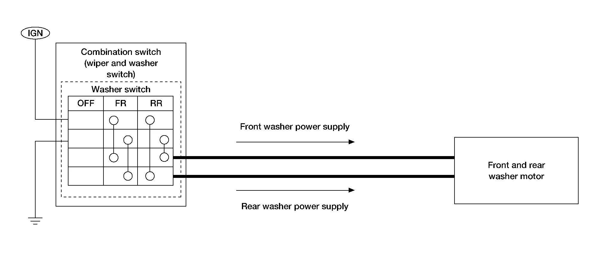
Washer Switch Circuit Nissan Pathfinder 5th Gen
Component Function Check
CHECK FRONT AND REAR WASHER OPERATION
When the front or rear washer switch is turned to the ON position the front and rear washers should operate.
Is front and rear washer operation normal?
YES>>Washer switch circuit is normal.
NO>>Refer to Diagnosis Procedure.
Diagnosis Procedure
WASHER SWITCH INSPECTION
Check washer switch. Refer to Component Inspection.
Is the inspection result normal?
YES>>GO TO 2.
NO>>Repair or replace the malfunctioning part.
CHECK FRONT AND REAR WASHER MOTOR FUSE
-
Ignition switch OFF.
-
Check that the following fuse is not blown (open):
| Location | Fuse No. | Capacity |
|---|---|---|
| Fuse block (J/B) | 60 | 10 A |
Is the fuse blown (open)?
YES>>Replace the blown fuse after repairing the affected circuit.
NO>>GO TO 3.
CHECK FRONT AND REAR WASHER MOTOR POWER SUPPLY CIRCUIT
-
Disconnect combination switch (wiper and washer switch) connector.
-
Ignition switch ON.
-
Check voltage between combination switch (wiper and washer switch) harness connector and ground.
| (+) | (−) |
Voltage (Approx.) | |
|---|---|---|---|
| Combination switch (wiper and washer switch) | |||
| Connector | Terminal | ||
| M28 | 11 | Ground | Battery voltage |
Is the inspection result normal?
YES>>GO TO 4.
NO>>Repair or replace harness.
CHECK FRONT AND REAR WASHER MOTOR GROUND CIRCUIT
-
Ignition switch OFF.
-
Check continuity between combination switch (wiper and washer switch) harness connector and ground.
Combination switch (wiper and washer switch) — Continuity Connector Terminal M28 9 Ground Yes
Is the inspection result normal?
YES>>GO TO 5.
NO>>Repair or replace harness.
CHECK FRONT AND REAR WASHER MOTOR CIRCUITS
-
Disconnect front and rear washer motor connector.
-
Check continuity between front and rear washer motor harness connector and combination switch (wiper and washer switch) harness connector.
Front and rear washer motor Combination switch (wiper and washer switch) Continuity Connector Terminal Connector Terminal E224 1 M28 16 Yes 2 14 -
Check continuity between front and rear washer motor harness connector and ground.
Front and rear washer motor — Continuity Connector Terminal E224 1 Ground No 2
Is the inspection result normal?
YES>>Replace front and rear washer motor. Refer to Removal and Installation.
NO>>Repair or replace harness.
Washer Switch Nissan Pathfinder Fifth generation
Description
-
Washer switch is integrated with the combination switch.
-
Washer switch switches polarity between front and rear washer operation to supply power and ground to the front and rear washer motor.
Component Inspection
CHECK FRONT WASHER SWITCH
-
Ignition switch OFF.
-
Disconnect combination switch (wiper and washer switch) connector.
-
Check continuity between the combination switch (wiper and washer switch) terminals.
A: Terminal 11 
B: Terminal 9 C: Terminal 14 D: Terminal 16
| Combination switch (wiper and washer switch) | Condition | Continuity | |
|---|---|---|---|
| Terminals | |||
| 11 | 14 | Front washer switch ON | Yes |
| 9 | 16 | ||
Is the inspection result normal?
YES>>GO TO 2.
NO>>Replace combination switch (wiper and washer switch). Refer to Removal and Installation.
CHECK REAR WASHER SWITCH
Check continuity between the combination switch (wiper and washer switch) terminals.
| A: Terminal 11 |
|
| B: Terminal 9 | |
| C: Terminal 14 | |
| D: Terminal 16 |
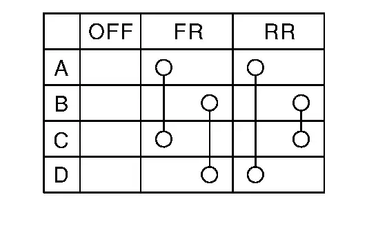
| Combination switch (wiper and washer switch) | Condition | Continuity | |
|---|---|---|---|
| Terminals | |||
| 11 | 16 | Rear washer switch ON | Yes |
| 9 | 14 | ||
Is the inspection result normal?
YES>>Combination switch (wiper and washer switch) is normal.
NO>>Replace combination switch (wiper and washer switch). Refer to Removal and Installation.
Rain Sensor Nissan Pathfinder 2026
Component Function Check
CHECK FRONT WIPER AUTO OPERATION
-
Clean the rain sensor detection area of windshield fully.
-
When the front wiper switch is turned to AUTO position, front wiper operates once regardless of a rainy condition.
Is front wiper (AUTO) operation normal?
YES>>Rain sensor is normal.
NO>>Refer to Diagnosis Procedure.
Diagnosis Procedure
CHECK FUSE
-
Ignition switch OFF.
-
Check that the following fuse is not blown (open):
Location Fuse No. Capacity Fuse block (J/B) 41 10 A
Is the fuse blown (open)?
YES>>Replace the blown fuse after repairing the affected circuit.
NO>>GO TO 2.
CHECK RAIN SENSOR POWER SUPPLY
-
Disconnect rain sensor connector.
-
Ignition switch ON.
-
Check voltage between rain sensor harness connector and ground.
(+) (−) Voltage
(Approx.)Rain sensor Connector Terminal R7 1 Ground Battery voltage
Is the inspection result normal?
YES>>GO TO 3.
NO>>Repair or replace harnesses.
CHECK RAIN SENSOR GROUND CIRCUIT
-
Ignition switch OFF.
-
Check continuity between rain sensor harness connector and ground.
Rain sensor (−) Continuity Connector Terminal R7 3 Ground Yes
Is the inspection result normal?
YES>>GO TO 4.
NO>>Repair or replace harness.
CHECK RAIN SENSOR LIN CIRCUIT
-
Disconnect BCM connector.
-
Check continuity between BCM harness connector and rain sensor harness connector.
BCM Rain sensor Continuity Connector Terminal Connector Terminal M18 25 R7 2 Yes -
Check continuity between rain sensor harness connector and ground.
Rain sensor (−) Continuity Connector Terminal R7 2 Ground No
Is the inspection result normal?
YES>>GO TO 5.
NO>>Repair or replace harness.
CHECK BCM LIN CIRCUIT
-
Connect BCM connector.
-
Ignition switch ON.
-
Check voltage between BCM harness connector and ground.
(+) (−) Voltage
(Approx.)BCM Connector Terminal M18 25 Ground Refer to Reference Value.
Is the inspection result normal?
YES>>Replace rain sensor. Refer to Removal and Installation.
NO>>Replace BCM. Refer to Removal and Installation.

Nissan Pathfinder (R53) 2022-2026 Service Manual
Dtc/circuit Diagnosis
- B20b2-72 Front Wiper Motor Circuit
- B2cb4-49 Rain Sensor
- B2cb5-64 Rear Wiper
- Front Wiper Motor Lo Circuit
- Front Wiper Auto Stop Position Signal Circuit
- Front Wiper Motor Ground Circuit
- Rear Wiper Motor Circuit
- Rear Wiper Stop Position Signal Circuit
- Washer Switch Circuit
- Washer Switch
- Rain Sensor
Contact Us
Nissan Pathfinder Info Center
Email: info@nipathfinder.com
Phone: +1 (800) 123-4567
Address: 123 Pathfinder Blvd, Nashville, TN 37214, USA
Working Hours: Mon–Fri, 9:00 AM – 5:00 PM (EST)
