Nissan Pathfinder: Interior Lighting System - Dtc/circuit Diagnosis
- Interior Room Lamp Power Supply Circuit
- Interior Room Lamp Control Circuit
- Map Lamp Control Circuit
- Personal Lamp Control Circuit
- Luggage Room Lamp Circuit
- Foot Lamp Circuit
- Vanity Mirror Lamp Circuit
- Mood Lamp Circuit
- Push-Button Ignition Switch Illumination Circuit
Interior Room Lamp Power Supply Circuit Nissan Pathfinder Fifth generation
Diagnosis Procedure
CHECK SYMPTOM
Check symptom (A or B).
| A |
All the following lamps do not turn ON:
|
| B | Interior room lamp battery saver does not activate. |
A>>
GO TO 2.
B>>GO TO 7.
CHECK FUSE
-
Ignition switch OFF.
-
Check that the following fuse is not blown (open).
Location Fuse No. Capacity Fuse block (J/B) 24 10 A
Is the fuse blown (open)?
YES>>Replace the blown (open) fuse after repairing the cause of blown (open).
NO>>GO TO 3.
CHECK INTERIOR ROOM LAMP RELAY CONTROL CIRCUIT 1
-
Disconnect interior room lamp relay connector.
-
Check voltage between interior room lamp relay harness connector and ground.
| (+) | (-) |
Voltage (Approx.) | |
|---|---|---|---|
| Interior room lamp relay | |||
| Connector | Terminal | ||
| J-2 | 1 | Ground | Battery voltage |
| 3 | |||
Is the inspection result normal?
YES>>GO TO 4.
NO>>Replace fuse block (J/B).
CHECK INTERIOR ROOM LAMP RELAY CONTROL CIRCUIT 2
-
Connect interior room lamp relay connector.
-
Disconnect BCM connector.
-
Check voltage between BCM harness connector and ground.
| (+) | (-) |
Voltage (Approx.) | |
|---|---|---|---|
| BCM | |||
| Connector | Terminal | ||
| M18 | 37 | Ground | Battery voltage |
Is the inspection result normal?
YES>>Replace BCM. Refer to Removal and Installation.
NO>>GO TO 5.
CHECK INTERIOR ROOM LAMP RELAY CONTROL CIRCUIT 3
-
Disconnect interior room lamp relay connector.
-
Check continuity between BCM harness connector and interior room lamp relay harness connector.
BCM Interior room lamp relay Continuity Connector Terminal Connector Terminal M18 37 J-2 2 Yes
Is the inspection result normal?
YES>>GO TO 6.
NO>>Repair or replace harness.
CHECK INTERIOR ROOM LAMP RELAY 1
Check interior room lamp relay. Refer to Component Inspection.
Is the inspection result normal?
YES>>Replace fuse block (J/B).
NO>>Replace interior room lamp relay.
CHECK INTERIOR ROOM LAMP RELAY 2
Check interior room lamp relay. Refer to Component Inspection.
Is the inspection result normal?
YES>>GO TO 8.
NO>>Replace interior room lamp relay.
CHECK INTERIOR ROOM LAMP RELAY CONTROL CIRCUIT 4
-
Disconnect BCM connector and interior room lamp relay connector.
-
Check continuity between BCM harness connector and ground.
BCM (-) Continuity Connector Terminal M18 37 Ground No
Is the inspection result normal?
YES>>GO TO 9.
NO>>Repair or replace harnesses.
CHECK INTERIOR ROOM LAMP RELAY POWER SUPPLY CIRCUIT
Check voltage between interior room lamp relay harness connector and ground.
| (+) | (-) |
Voltage (Approx.) | |
|---|---|---|---|
| Interior room lamp relay | |||
| Connector | Terminal | ||
| J-2 | 5 | Ground | 0 V |
Is the inspection result normal?
YES>>Replace BCM. Refer to Removal and Installation.
NO>>Repair or replace harnesses.
Component Inspection
CHECK INTERIOR ROOM LAMP RELAY
-
Ignition switch OFF.
-
Disconnect interior room lamp relay connector.
-
Check continuity between interior room lamp relay terminals.
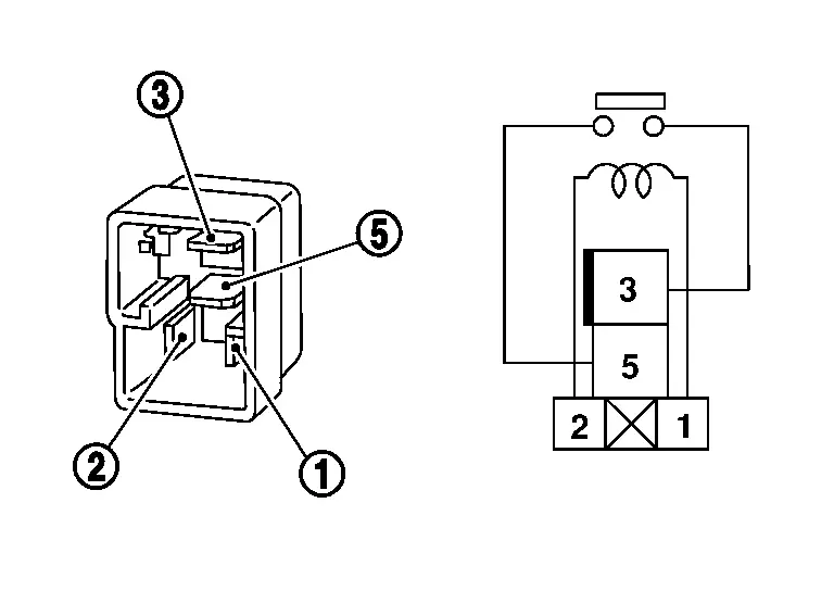
Interior room lamp relay Condition Continuity Terminal 

12 V direct current supply between terminals  and
and
 .
. Yes No current supply No
Is the inspection result normal?
YES>>Inspection End.
NO>>Replace interior room lamp relay.
Interior Room Lamp Control Circuit Nissan Pathfinder 2022
Component Function Check
CAUTION:
Before performing the diagnosis, check that the following are normal:
-
Interior room lamp power supply circuit
-
Each interior room lamp bulb
CHECK INTERIOR ROOM LAMP OPERATION
 CONSULT
-
Switch the map lamp switch to DOOR.
-
Open the front door LH.
-
Ignition switch ON.
-
Select “INT LAMP” in "Active Test" mode of "BCM(INT LAMP)".
-
With operating the test items, check that interior room lamp turns ON/OFF.
On : Interior room lamp turns ON Off : Interior room lamp turns OFF
Does the interior room lamp turn ON/OFF?
YES>>Interior room lamp control circuit is normal.
NO>>Refer to Diagnosis Procedure.
Diagnosis Procedure
 NOTE:
NOTE:
Before performing the diagnosis, check that the interior room lamp bulb is normal.
CHECK INTERIOR ROOM LAMP POWER SUPPLY CIRCUIT
-
Ignition switch OFF.
-
Disconnect following connectors:
-
Interior room lamp relay
-
Front room/map lamp assembly
-
Personal lamps 2nd row
-
Cargo lamp
-
-
Check continuity between interior room lamp relay harness connector and each interior room lamp harness connector.
Interior room lamp relay Each interior room lamp Continuity Connector Terminal Connector Terminal J-2 5 Front room/map lamp assembly R107 1 Yes Personal lamps 2nd row R106 2 Cargo lamp R104 2
Is the inspection result normal?
YES>>GO TO 2.
NO>>Repair or replace harnesses.
CHECK INTERIOR ROOM LAMP GROUND CIRCUIT
Check continuity between each interior room lamp harness connector and ground.
| Each interior room lamp | (-) | Continuity | ||
|---|---|---|---|---|
| Connector | Terminal | |||
| Front room/map lamp assembly | R107 | 2 | Ground | Yes |
| Personal lamps 2nd row | R106 | 4 | ||
| Cargo lamp | R104 | 1 | ||
Is the inspection result normal?
YES>>Map lamp: Replace corresponding front room/map lamp assembly bulb. Refer to Bulb or Lens Replacement.
YES>>Personal lamp: Replace corresponding personal lamp bulb. Refer to Bulb or Lens Replacement.
YES>>Cargo lamp: Replace cargo lamp bulb. Refer to Bulb or Lens Replacement.
NO>>Repair or replace harnesses.
Map Lamp Control Circuit Nissan Pathfinder
Component Function Check
CAUTION:
Before performing the diagnosis, check that the following are normal:
-
Interior room lamp power supply circuit
-
Interior room lamp control circuit
-
Front room/map lamp assembly bulb
CHECK MAP LAMP OPERATION
 CONSULT
-
Switch the map lamp switch to DOOR.
-
Open the front door LH.
-
Ignition switch ON.
-
Select “INT LAMP” in "Active Test" mode of "BCM(INT LAMP)".
-
With operating the test items, check that map lamp turns ON/OFF.
On : Map lamp turns ON Off : Map lamp turns OFF
Does the map lamp turn ON/OFF?
YES>>Map lamp control circuit is normal.
NO>>Refer to Diagnosis Procedure.
Diagnosis Procedure
CHECK MAP LAMP CONTROL SIGNAL CIRCUIT 1
-
Ignition switch OFF.
-
Disconnect front room/map lamp assembly connector, personal lamps 2nd row connector and cargo lamp connector.
-
Ignition switch ON.
-
Check continuity between BCM harness connector and ground.
BCM — Condition Continuity Connector Terminal M81 130 Ground Front door LH Open Yes Close No
Is the inspection result normal?
YES>>GO TO 2.
NO>>Continuity exists and remains unchanged: GO TO 3.
NO>>Continuity does not exist and remains unchanged: Replace BCM. Refer to Removal and Installation.
CHECK MAP LAMP CONTROL SIGNAL CIRCUIT 2
-
Ignition switch OFF.
-
Disconnect BCM connector.
-
Check continuity between BCM harness connector and front room/map lamp assembly harness connector.
BCM Front room/map lamp assembly Continuity Connector Terminal Connector Terminal M81 130 R107 4 Yes
Is the inspection result normal?
YES>>Replace front room/map lamp assembly. Refer to Removal and Installation.
NO>>Repair or replace harnesses.
CHECK MAP LAMP CONTROL SIGNAL CIRCUIT 3
-
Ignition switch OFF.
-
Disconnect BCM connector.
-
Check continuity between BCM harness connector and ground.
BCM — Continuity Connector Terminal M81 130 Ground No
Is the inspection result normal?
YES>>Replace BCM. Refer to Removal and Installation.
NO>>Repair or replace harnesses.
Personal Lamp Control Circuit Nissan Pathfinder 5th Gen
Component Function Check
CAUTION:
Before performing the diagnosis, check that the following are normal:
-
Interior room lamp power supply circuit
-
Interior room lamp control circuit
-
Each personal lamp bulb
CHECK MAP LAMP OPERATION
-
Switch the map lamp switch to DOOR.
-
Check that map lamp turns ON when any door is opened (except back door).
Is the inspection normal?
YES>>GO TO 2.
NO>>Check map lamp control circuit. Refer to Component Function Check .
CHECK PERSONAL LAMP OPERATION
 CONSULT
-
Switch the map lamp switch and personal lamp switch to DOOR.
-
Open the front door LH.
-
Ignition switch ON.
-
Select “INT LAMP” in "Active Test" mode of "BCM(INT LAMP)".
-
With operating the test items, check that personal lamp turns ON/OFF.
On : Personal lamp turns ON Off : Personal lamp turns OFF
Does the personal lamp turns ON/OFF?
YES>>Personal lamp control circuit is normal.
NO>>Refer to Diagnosis Procedure.
Diagnosis Procedure
CHECK PERSONAL LAMP CONTROL CIRCUIT
-
Ignition switch OFF.
-
Disconnect front room/map lamp assembly connector and personal lamps 2nd row connector.
-
Check continuity between front room/map lamp assembly harness connector and personal lamps 2nd row harness connector.
Front room/map lamp assembly Personal lamps 2nd row Continuity Connector Terminal Connector Terminal R107 8 R106 3 Yes
Is the inspection result normal?
YES>>GO TO 2.
NO>>Repair or replace harnesses.
CHECK MAP LAMP CIRCUIT
Check continuity between map lamp assembly terminals.
| Front room/map lamp assembly | Condition | Continuity | |
|---|---|---|---|
| Terminal | |||
| 4 | 8 | Map lamp switch (DOOR) is "DOOR" position | Yes |
| Map lamp switch (DOOR) is "OFF" position | No | ||
Is the inspection result normal?
YES>>Replace corresponding personal lamp. Refer to Removal and Installation.
NO>>Replace front room/map lamp assembly. Refer to Removal and Installation .
Luggage Room Lamp Circuit Nissan Pathfinder 5th Gen
Component Function Check
CAUTION:
Before performing the diagnosis, check that the following are normal:
-
Interior room lamp power supply circuit
-
Luggage room lamp bulb
CHECK LUGGAGE ROOM LAMP OPERATION
-
Ignition switch ON.
-
Check that the luggage room lamp turns on when the back door is open.
Does luggage room lamp turn ON/OFF?
YES>>Luggage room lamp circuit is normal.
NO>>Refer to Diagnosis Procedure.
Diagnosis Procedure
CHECK LUGGAGE ROOM LAMP POWER SUPPLY CIRCUIT
-
Ignition switch OFF.
-
Disconnect interior room lamp relay connector, foot lamp LH connector, foot lamp RH connector and luggage room lamp connector.
-
Check continuity between interior room lamp relay harness connector and luggage room lamp harness connector.
Interior room lamp relay Luggage room lamp Continuity Connector Terminal Connector Terminal J-2 5 D567 1 Yes
Is the inspection normal?
YES>>GO TO 2.
NO>>Repair or replace harness.
CHECK LUGGAGE ROOM LAMP CONTROL SIGNAL CIRCUIT 1
-
Ignition switch ON.
-
Check continuity between BCM harness connector and ground.
BCM (-) Condition Continuity Connector Terminal M18 30 Ground Back door Open Yes Close No B45 147
Is the inspection result normal?
YES>>GO TO 3.
NO>>Continuity exists and remains unchanged: GO TO 4.
NO>>Continuity does not exist and remains unchanged: Replace BCM. Refer to Removal and Installation.
CHECK LUGGAGE ROOM LAMP CONTROL SIGNAL CIRCUIT 2
-
Ignition switch OFF.
-
Disconnect BCM connector.
-
Check continuity between BCM harness connector and luggage room lamp harness connector.
BCM Luggage room lamp Continuity Connector Terminal Connector Terminal M18 30 D567 2 Yes B45 147
Is the inspection result normal?
YES>>Replace luggage room lamp bulb. Refer to Bulb Replacement.
NO>>Repair or replace harnesses.
CHECK LUGGAGE ROOM LAMP CONTROL SIGNAL CIRCUIT 3
-
Ignition switch OFF.
-
Disconnect BCM connector.
-
Check continuity between BCM harness connector and ground.
BCM (-) Continuity Connector Terminal M18 30 Ground No B45 147
Is the inspection result normal?
YES>>Replace BCM. Refer to Removal and Installation.
NO>>Repair or replace harnesses.
Foot Lamp Circuit Nissan Pathfinder 2022
Component Function Check
CAUTION:
Before performing the diagnosis, check that the following are normal:
-
Interior room lamp power supply circuit
-
Each foot lamp bulb
CHECK FOOT LAMP OPERATION
-
Ignition switch ON.
-
Check that the foot lamp turns on when any door is opened (except back door).
Does foot lamp turn ON/OFF?
YES>>Foot lamp circuit is normal.
NO>>Refer to Diagnosis Procedure.
Diagnosis Procedure
CHECK FOOT LAMP POWER SUPPLY CIRCUIT
-
Ignition switch OFF.
-
Disconnect interior room lamp relay connector, luggage room lamp connector, foot lamp LH connector and foot lamp RH connector.
-
Check continuity between interior room lamp relay harness connector and each foot lamp harness connector.
Interior room lamp relay Foot lamp Continuity Connector Terminal Connector Terminal J-2 5 Foot lamp LH M99 1 Yes Foot lamp RH M100
Is the inspection normal?
YES>>GO TO 2.
NO>>Repair or replace harness.
CHECK FOOT LAMP CONTROL SIGNAL CIRCUIT 1
-
Ignition switch ON.
-
Check continuity between BCM harness connector and ground.
BCM (-) Condition Continuity Connector Terminal M18 30 Ground Front door LH Open Yes Close No B45 147
Is the inspection result normal?
YES>>GO TO 3.
NO>>Continuity exists and remains unchanged: GO TO 4.
NO>>Continuity does not exist and remains unchanged: Replace BCM. Refer to Removal and Installation.
CHECK FOOT LAMP CONTROL SIGNAL CIRCUIT 2
-
Ignition switch OFF.
-
Disconnect BCM connector.
-
Check continuity between BCM harness connector and each foot lamp harness connector.
Foot lamp LH BCM Foot lamp LH Continuity Connector Terminal Connector Terminal M18 30 M99 2 Yes B45 147 Foot lamp RH BCM Foot lamp RH Continuity Connector Terminal Connector Terminal M18 30 M100 2 Yes B45 147
Is the inspection result normal?
YES>>Replace corresponding foot lamp bulb. Refer to Bulb Replacement (foot lamp LH) or Bulb Replacement (foot lamp RH).
NO>>Repair or replace harnesses.
CHECK FOOT LAMP CONTROL SIGNAL CIRCUIT 3
-
Ignition switch OFF.
-
Disconnect BCM connector.
-
Check continuity between BCM harness connector and ground.
BCM (-) Continuity Connector Terminal M18 30 Ground No B45 147
Is the inspection result normal?
YES>>Replace BCM. Refer to Removal and Installation.
NO>>Repair or replace harnesses.
Vanity Mirror Lamp Circuit Nissan Pathfinder R53
Diagnosis Procedure
CAUTION:
Before performing the diagnosis, check that the following are normal:
-
Interior room lamp power supply circuit
CHECK VANITY MIRROR LAMP POWER SUPPLY CIRCUIT 1
-
Ignition switch OFF.
-
Disconnect interior room lamp relay connector and sunvisor (vanity mirror lamp switch) connector.
-
Check continuity between interior room lamp relay harness connector and each sunvisor (vanity mirror lamp switch) harness connector.
Interior room lamp relay Sunvisor (vanity mirror lamp switch) Continuity Connector Terminal Connector Terminal J-2 5 RH R130 1 Yes LH R129
Is the inspection result normal?
YES>>GO TO 2.
NO>>Repair or replace harnesses.
CHECK VANITY MIRROR LAMP POWER SUPPLY CIRCUIT 2
-
Disconnect vanity mirror lamp connector.
-
Check continuity between each sunvisor (vanity mirror lamp switch) harness connector and each vanity mirror lamp harness connector.
Sunvisor (vanity mirror lamp switch) Vanity mirror lamp Continuity Connector Terminal Connector Terminal RH R130 2 R102 2 Yes LH R129 R103
Is the inspection result normal?
YES>>GO TO 3.
NO>>Repair or replace harness.
CHECK VANITY MIRROR LAMP SWITCH
Check vanity mirror lamp switch. Refer to Component Inspection.
YES>>
GO TO 4.
NO>>Replace corresponding sun visor (vanity mirror lamp switch). Refer to Removal and Installation.
CHECK VANITY MIRROR LAMP GROUND CIRCUIT
Check continuity between vanity mirror lamp harness connector and ground.
| Vanity mirror lamp | (-) | Continuity | ||
|---|---|---|---|---|
| Connector | Terminal | |||
| RH | R102 | 3 | Ground | Yes |
| LH | R103 | |||
Is the inspection result normal?
YES>>Replace corresponding vanity mirror lamp. Refer to Removal and Installation.
NO>>Repair or replace harnesses.
Component Inspection
CHECK VANITY MIRROR LAMP SWITCH
-
Ignition switch OFF.
-
Disconnect sunvisor (vanity mirror lamp switch) connector.
-
Check continuity between sunvisor (vanity mirror lamp switch) terminals.
Sunvisor (vanity mirror lamp switch) Condition Continuity Terminal 1 2 Sunvisor OPEN (vanity mirror lamp switch ON) Yes Sunvisor CLOSE (vanity mirror lamp switch OFF) No
Is the inspection result normal?
YES>>Inspection End.
NO>>Replace corresponding sunvisor (vanity mirror lamp switch). Refer to Exploded View.
Mood Lamp Circuit Nissan Pathfinder SUV
Component Function Check
CAUTION:
Before performing the diagnosis, check that the following are normal:
-
Interior room lamp power supply circuit
CHECK MOOD LAMP OPERATION
 CONSULT
-
Open the front door LH.
-
Ignition switch ON.
-
Select “INT LAMP” in "Active Test" mode of "BCM(INT LAMP)".
-
With operating the test items, check that mood lamp turns ON/OFF.
On : Mood lamp turns ON Off : Mood lamp turns OFF
Does the mood lamp turns ON/OFF?
YES>>Mood lamp circuit is normal.
NO>>Refer to Diagnosis Procedure.
Diagnosis Procedure
CHECK MOOD LAMP POWER SUPPLY CIRCUIT
-
Ignition switch OFF.
-
Disconnect interior room lamp relay connector and mood lamp connector.
-
Check continuity between interior room lamp relay harness connector and each mood lamp harness connector.
Interior room lamp relay Mood lamp Continuity Connector Terminal Connector Terminal J-2 5 Mood lamp (front door RH) D139 2 Yes Mood lamp (front door LH) D39 Mood lamp (rear door RH) D318 Mood lamp (rear door LH) D219 Mood lamp (instrument panel RH) M196 Mood lamp (instrument panel LH) M190 Mood lamp (center console tray RH) M199 Mood lamp (center console tray LH) M198 Mood lamp (center console) M14 1
Is the inspection normal?
YES>>GO TO 2.
NO>>Repair or replace harness.
CHECK MOOD LAMP CONTROL SIGNAL CIRCUIT 1
-
Ignition switch ON.
-
Check continuity between BCM harness connector and ground.
BCM (-) Condition Continuity Connector Terminal B45 150 Ground Front door LH Open Yes Close No
Is the inspection result normal?
YES>>GO TO 3.
NO>>Continuity exists and remains unchanged: GO TO 4.
NO>>Continuity does not exist and remains unchanged: Replace BCM. Refer to Removal and Installation.
CHECK MOOD LAMP CONTROL SIGNAL CIRCUIT 2
-
Ignition switch OFF.
-
Disconnect BCM connector.
-
Check continuity between BCM harness connector and each mood lamp harness connector.
BCM Mood lamp Continuity Connector Terminal Connector Terminal B45 150 Mood lamp (front door RH) D139 3 Yes Mood lamp (front door LH) D39 Mood lamp (rear door RH) D318 Mood lamp (rear door LH) D219 Mood lamp (instrument panel RH) M196 Mood lamp (instrument panel LH) M190 Mood lamp (center console tray RH) M199 Mood lamp (center console tray LH) M198 Mood lamp (center console) M14 2
Is the inspection result normal?
YES>>Mood lamp (front door): Replace corresponding mood lamp (front door). Refer to Removal and Installation.
YES>>Mood lamp (rear door): Replace corresponding mood lamp (rear door). Refer to Removal and Installation.
YES>>Mood lamp (instrument panel): Replace corresponding mood lamp (instrument panel). Refer to Exploded View.
YES>>Mood lamp (center console tray): Replace corresponding mood lamp (center console tray). Refer to Removal and Installation.
YES>>Mood lamp (center console): Replace mood lamp (center console). Refer to Removal and Installation.
NO>>Repair or replace harnesses.
CHECK MOOD LAMP CONTROL SIGNAL CIRCUIT 3
-
Ignition switch OFF.
-
Disconnect BCM connector.
-
Check continuity between BCM harness connector and ground.
BCM (-) Continuity Connector Terminal B45 150 Ground No
Is the inspection result normal?
YES>>Replace BCM. Refer to Removal and Installation.
NO>>Repair or replace harnesses.
Push-Button Ignition Switch Illumination Circuit Nissan Pathfinder Fifth generation
Diagnosis Procedure
CHECK PUSH-BUTTON IGNITION SWITCH ILLUMINATION POWER SUPPLY 1
-
Ignition switch OFF.
-
Disconnect Intelligent Key unit connector and push-button ignition switch connector.
-
Check continuity between BCM harness connector and ground.
Intelligent Key unit — Continuity Connector Terminal M38 10 Ground No
Is the inspection result normal?
YES>>GO TO 2.
NO>>Repair or replace harnesses.
CHECK PUSH-BUTTON IGNITION SWITCH ILLUMINATION POWER SUPPLY 2
-
Connect Intelligent Key unit connector and push-button ignition switch connector.
-
Ignition switch ON.
-
Check voltage between Intelligent Key unit harness connector and the ground.
(+) (–) Condition Voltage
(Approx.)Intelligent Key unit Connector Terminal M38 10 Ground Push-button ignition switch illumination ON Battery voltage OFF 0 V
Is the inspection result normal?
YES>>GO TO 3.
NO>>Replace Intelligent Key unit. Refer to Removal and Installation.
CHECK PUSH-BUTTON IGNITION SWITCH ILLUMINATION CIRCUIT
-
Ignition switch OFF.
-
Disconnect Intelligent Key unit connector and push-button ignition switch connector.
-
Check continuity between Intelligent Key unit harness connector and push-button ignition switch harness connector.
Intelligent Key unit Push-button ignition switch Continuity Connector Terminal Connector Terminal M38 10 M17 5 Yes
Is the inspection result normal?
YES>>GO TO 4.
NO>>Repair or replace harnesses.
CHECK PUSH-BUTTON IGNITION SWITCH ILLUMINATION GROUND CIRCUIT
Check continuity between push-button ignition switch harness connector and ground.
| Push-button ignition switch | — | Continuity | |
|---|---|---|---|
| Connector | Terminal | ||
| M17 | 6 | Ground | Yes |
Is the inspection result normal?
YES>>Replace push-button ignition switch. Refer to Removal and Installation.
NO>>Repair or replace harnesses.

Nissan Pathfinder (R53) 2022-2026 Service Manual
Dtc/circuit Diagnosis
- Interior Room Lamp Power Supply Circuit
- Interior Room Lamp Control Circuit
- Map Lamp Control Circuit
- Personal Lamp Control Circuit
- Luggage Room Lamp Circuit
- Foot Lamp Circuit
- Vanity Mirror Lamp Circuit
- Mood Lamp Circuit
- Push-Button Ignition Switch Illumination Circuit
Contact Us
Nissan Pathfinder Info Center
Email: info@nipathfinder.com
Phone: +1 (800) 123-4567
Address: 123 Pathfinder Blvd, Nashville, TN 37214, USA
Working Hours: Mon–Fri, 9:00 AM – 5:00 PM (EST)
