Nissan Pathfinder: Security Control System - Dtc/circuit Diagnosis
- P161d-00 Immobilizer
- P161e-00 Immobilizer
- P161f-00 Immobilizer
- B2c20-12 Starter Control Relay
- B2c20-23 Starter Control Relay
- B2f70-01 Stop Lamp
- B2f71-23 Stop Lamp
- B2f72-23 Stop Lamp
- B2080 Power Switch
- B2033-4a Dongle Ng
- B2042-4a Electric Shift Authentication Fail
- B2043-4a Electric Shift Id Discord
- B2070-68 Key Registration
- B2090-14 Nats Antenna Amp.
- Hood Switch
- Horn Function
- Starter Cut Relay
- Stop Lamp Switch
- Brake Pedal Position Switch
P161d-00 Immobilizer Nissan Pathfinder R53
DTC Description
DTC DETECTION LOGIC
| DTC No. |
CONSULT screen items (Trouble diagnosis content) | DTC detecting condition | |
|---|---|---|---|
| P161D-00 |
IMMOBILIZER (Immobilizer) |
Diagnosis condition | Ignition switch ON |
| Signal (terminal) | — | ||
| Threshold | When key registration has not been completed normally after replacing Intelligent Key unit. | ||
| Diagnosis delay time | 1 second or less | ||
POSSIBLE CAUSE
-
Improper key registration operation
-
EPS control unit
-
Intelligent Key unit
FAIL-SAFE
—
CONFIRMATION PROCEDURE
PERFORM DTC CONFIRMATION PROCEDURE
 CONSULT
-
Ignition switch ON.
-
Select “Self Diagnostic Result” mode of “ENGINE”.
Is the DTC detected?
YES>>Refer to DTC Diagnosis Procedure.
NO>>To check malfunction symptom before repair: Refer to Intermittent Incident.
NO>>Confirmation after repair: Inspection End.
DTC Diagnosis Procedure
CHECK DTC PRIORITY OF INTELLIGENT KEY UNIT
If DTC P161D-00 is displayed with DTC B2033-4A, first perform the trouble diagnosis for DTC B2033-4A.
Is DTC B2033-4A detected?
YES>>Perform diagnosis of applicable. DTC B2033-4A: Refer to DTC Description.
NO>>GO TO 2.
INTELLIGENT KEY REGISTRATION
 CONSULT
-
Perform registration of all Intelligent Keys.
For registration procedures, refer to CONSULT immobilizer mode and follow the on-screen instructions.
-
Erase DTC.
-
Perform DTC confirmation procedure for DTC P161D-00. Refer to DTC Description.
Is DTC P161D-00 detected?
YES>>GO TO 3.
NO>>Inspection End.
REPLACE INTELLIGENT KEY UNIT
-
Replace Intelligent Key unit. Refer to Removal and Installation.
-
Erase DTC.
-
Perform DTC confirmation procedure for DTC P161D-00. Refer to DTC Description.
-
Check that the DTC is not detected.
>>
Inspection End.
P161e-00 Immobilizer Nissan Pathfinder Fifth generation
DTC Description
DTC DETECTION LOGIC
| DTC No. |
CONSULT screen items (Trouble diagnosis content) | DTC detecting condition | |
|---|---|---|---|
| P161E-00 |
IMMOBILIZER (Immobilizer) |
Diagnosis condition | Ignition switch ON |
| Signal (terminal) | — | ||
| Threshold | When CONSULT is not used during ECM replacement. | ||
| Diagnosis delay time | 1 second or less | ||
POSSIBLE CAUSE
-
Intelligent Key unit
-
ECM
FAIL-SAFE
Inhibit engine cranking
CONFIRMATION PROCEDURE
PERFORM DTC CONFIRMATION PROCEDURE
 CONSULT
-
Ignition switch ON.
-
Select “Self Diagnostic Result” mode of “ENGINE”.
Is the DTC detected?
YES>>Refer to DTC Diagnosis Procedure.
NO>>To check malfunction symptom before repair: Refer to Intermittent Incident.
NO>>Confirmation after repair: Inspection End.
DTC Diagnosis Procedure
ECM REGISTRATION
 CONSULT
Register ECM.
Is the DTC detected?
YES>>GO TO 2.
NO>>Inspection End.
REPLACE INTELLIGENT KEY UNIT
Replace Intelligent Key unit. Refer to Removal and Installation.
Is the DTC detected?
YES>>GO TO 3.
NO>>Inspection End.
REPLACE ECM
Replace ECM. Refer to Removal and Installation.
>>
Inspection End.
P161f-00 Immobilizer Nissan Pathfinder Fifth generation
DTC Description
DTC DETECTION LOGIC
| DTC No. |
CONSULT screen items (Trouble diagnosis content) | DTC detecting condition | |
|---|---|---|---|
| P161F-00 |
IMMOBILIZER (Immobilizer) |
Diagnosis condition | Ignition switch ON |
| Signal (terminal) | — | ||
| Threshold | When Intelligent Key unit detects an immobilizer malfunction and engine start is prohibited. | ||
| Diagnosis delay time | 1 second or less | ||
POSSIBLE CAUSE
ECM
FAIL-SAFE
Inhibit engine cranking
CONFIRMATION PROCEDURE
PERFORM DTC CONFIRMATION PROCEDURE
 CONSULT
-
Ignition switch ON.
-
Select “Self Diagnostic Result” mode of “ENGINE”.
Is the DTC detected?
YES>>Refer to DTC Diagnosis Procedure.
NO>>To check malfunction symptom before repair: Refer to Intermittent Incident.
NO>>Confirmation after repair: Inspection End.
DTC Diagnosis Procedure
REPLACE ECM
Replace ECM. Refer to Removal and Installation.
>>
Inspection End.
B2c20-12 Starter Control Relay Nissan Pathfinder 2026
DTC Description
DTC DETECTION LOGIC
| DTC No. |
CONSULT screen items (Trouble diagnosis content) | DTC detecting condition | |
|---|---|---|---|
| B2C20-12 |
Starter control relay (Starter control relay) |
Diagnosis condition | Ignition switch ON |
| Signal (terminal) | Starter cut relay signal | ||
| Threshold | When BCM detects starter cut relay circuit is short to buttery | ||
| Diagnosis delay time | 1 second or less | ||
POSSIBLE CAUSE
-
Harness or connectors
(Starter cut relay circuit is short to battery)
-
Starter cut relay
FAIL-SAFE
—
CONFIRMATION PROCEDURE
PERFORM DTC CONFIRMATION PROCEDURE
 CONSULT
-
Press ignition switch under the following conditions and wait 1 second or more.
-
Selector lever: In the P position.
-
Brake pedal: Depressed.
-
-
Select “Self Diagnostic Result” mode of “BCM”.
Is the DTC detected?
YES>>Refer to DTC Diagnosis Procedure.
NO>>To check malfunction symptom before repair: Refer to Intermittent Incident.
NO>>Confirmation after repair: Inspection End.
DTC Diagnosis Procedure
CHECK STARTER CUT RELAY INPUT SIGNAL
Check voltage between BCM harness connector and ground.
| (+) | (-) | Condition |
Voltage (Approx.) | |
|---|---|---|---|---|
| BCM | ||||
| Connector | Terminal | |||
| M80 | 123 | Ground | Other than following | Battery voltage |
| At engine cranking | 0 V | |||
Is the inspection result normal?
YES>>Inspection End.
NO>>GO TO 2.
CHECK STARTER CUT RELAY INPUT SIGNAL CIRCUIT
-
Ignition switch OFF.
-
Disconnect BCM connector and starter cut relay connector.
-
Check continuity between BCM harness connector and starter cut relay harness connector.
BCM Starter cut relay Continuity Connector Terminal Connector Terminal M80 123 E36 8 Yes -
Check continuity between BCM harness connector and ground.
BCM (–) Continuity Connector Terminal M80 123 Ground No
Is the inspection result normal?
YES>>GO TO 3.
NO>>Repair or replace harness.
CHECK STARTER CUT RELAY
Check starter cut relay. Refer to Component Inspection.
Is the inspection result normal?
YES>>Inspection End.
NO>>Replace starter cut relay.
B2c20-23 Starter Control Relay Nissan Pathfinder SUV
DTC Description
DTC DETECTION LOGIC
| DTC No. |
CONSULT screen items (Trouble diagnosis content) | DTC detecting condition | |
|---|---|---|---|
| B2C20-23 |
Starter control relay (Starter control relay) |
Diagnosis condition | Ignition switch ON |
| Signal (terminal) |
|
||
| Threshold | When the starter cut relay status signal transmitted from IPDM E/R via CAN communication is OFF after even though BCM is operating the starter cut relay ON output. | ||
| Diagnosis delay time | 1 second or less | ||
POSSIBLE CAUSE
-
Harness or connectors
(The CAN communication line is open or shorted)
-
Harness or connectors
(Starter cut relay circuit is short to ground or open)
-
Starter cut relay
FAIL-SAFE
—
CONFIRMATION PROCEDURE
PERFORM DTC CONFIRMATION PROCEDURE
 CONSULT
-
Press ignition switch under the following conditions and wait 1 second or more.
-
Selector lever: In the P position.
-
Brake pedal: Depressed.
-
-
Select “Self Diagnostic Result” mode of “BCM”.
Is the DTC detected?
YES>>Refer to DTC Diagnosis Procedure.
NO>>To check malfunction symptom before repair: Refer to Intermittent Incident.
NO>>Confirmation after repair: Inspection End.
DTC Diagnosis Procedure
CHECK STARTER CUT RELAY INPUT SIGNAL
Check voltage between BCM harness connector and ground.
| (+) | (-) | Condition |
Voltage (Approx.) | |
|---|---|---|---|---|
| BCM | ||||
| Connector | Terminal | |||
| M80 | 123 | Ground | Other than following | Battery voltage |
| At engine cranking | 0 V | |||
Is the inspection result normal?
YES>>GO TO 4.
NO>>GO TO 2.
CHECK STARTER CUT RELAY INPUT SIGNAL CIRCUIT
-
Ignition switch OFF.
-
Disconnect BCM connector and starter cut relay connector.
-
Check continuity between BCM harness connector and starter cut relay harness connector.
BCM Starter cut relay Continuity Connector Terminal Connector Terminal M80 123 E36 8 Yes -
Check continuity between BCM harness connector and ground.
BCM — Continuity Connector Terminal M80 123 Ground No
Is the inspection result normal?
YES>>GO TO 3.
NO>>Repair or replace harness.
CHECK FUSIBLE LINK
Check that the following fusible link is not blown (open).
| Signal name | Fusible link | Capacity |
|---|---|---|
| Battery power supply | R | 30 A |
Is the fusible link blown (open)?
YES>>Replace the blown (open) fusible link after repairing the affected circuit if a fusible link is blown (open).
NO>>GO TO 6.
CHECK STARTER CUT RELAY OUTPUT SIGNAL
Check voltage between IPDM E/R harness connector and ground.
| (+) | (-) | Condition |
Voltage (Approx.) | |
|---|---|---|---|---|
| IPDM E/R | ||||
| Connector | Terminal | |||
| E77 | 86 | Ground | Other than at engine cranking | Less than 4 V (IPDM E/R always outputs the voltage to detect the ON/ OFF state of starter cut relay) |
| At engine cranking | Battery voltage | |||
Is the inspection result normal?
YES>>Inspection End.
NO>>GO TO 5.
CHECK STARTER CUT RELAY OUTPUT SIGNAL CIRCUIT
-
Ignition switch OFF.
-
Disconnect IPDM E/R connector and starter cut relay connector.
-
Check continuity between IPDM E/R harness connector and starter cut relay harness connector.
IPDM E/R Starter cut relay Continuity Connector Terminal Connector Terminal E77 86 E36 6 Yes -
Check continuity between IPDM E/R harness connector and ground.
IPDM E/R — Continuity Connector Terminal E77 86 Ground No
Is the inspection result normal?
YES>>GO TO 6.
NO>>Repair or replace harness.
CHECK STARTER CUT RELAY
Check starter cut relay. Refer to Component Inspection.
Is the inspection result normal?
YES>>Inspection End.
NO>>Replace starter cut relay.
B2f70-01 Stop Lamp Nissan Pathfinder 2026
DTC Description
DTC DETECTION LOGIC
| DTC No. |
CONSULT screen items (Trouble diagnosis content) | DTC detecting condition | |
|---|---|---|---|
| B2F70-01 |
Stop lamp (Stop lamp) |
Diagnosis condition | When brake pedal is depressed |
| Signal (terminal) |
|
||
| Threshold | BCM makes a comparison between stop lamp switch 1 signal and stop lamp switch 2 signal. It judges from their values to detect the malfunctioning circuit 10 consecutive times | ||
| Diagnosis delay time | Depress brake pedal 10 times | ||
POSSIBLE CAUSE
-
Harness or connectors
(Stop lamp switch circuit is open or shorted)
-
Stop lamp switch
-
Fuse
FAIL-SAFE
—
CONFIRMATION PROCEDURE
PERFORM DTC CONFIRMATION PROCEDURE
 CONSULT
-
Depress brake pedal 10 times.
-
Ignition switch ON.
-
Check DTC in “Self Diagnostic Result” mode of “BCM”.
Is DTC detected?
YES>>Refer to DTC Diagnosis Procedure.
NO>>To check malfunction symptom before repair: Refer to Intermittent Incident.
NO>>Confirmation after repair: Inspection End.
DTC Diagnosis Procedure
CHECK BRAKE PEDAL POSITION SWITCH
 CONSULT
-
Select “Brake switch 1” and “Brake switch 2” in “Data Monitor” mode of “SIGNAL BUFFER” of “BCM”.
-
Check “Brake switch 1” and “Brake switch 2” indication under the following condition.
| Monitor item | Condition | Indication | |
|---|---|---|---|
| Brake switch 1 | Brake pedal | Depressed | Off |
| Not depressed | On | ||
| Brake switch 2 | Depressed | On | |
| Not depressed | Off | ||
Is the indication normal?
YES>>Brake pedal position switch is OK.
NO>>Brake switch 1: GO TO 2.
NO>>Brake switch 2: GO TO 7.
CHECK FUSE
Check that the following fuse is not blown (open).
| Signal name | Fuse No. | Capacity |
|---|---|---|
| Battery power supply | 32 | 10 A |
Is the fuse blown (open)?
YES>>Replace the blown (open) fuse after replacing the cause of blown (open).
NO>>GO TO 3.
CHECK BRAKE PEDAL POSITION SWITCH SIGNAL
-
Ignition switch OFF.
-
Disconnect BCM connector.
-
Ignition switch ON.
-
Check voltage between BCM harness connector and ground.
(+) (–) Condition Voltage
(Approx.)BCM Connector Terminal M80 111 Ground Brake pedal position switch 1 ON (brake pedal is not depressed) Battery voltage Brake pedal position switch 1 OFF (brake pedal is depressed) 0 V
Is the inspection normal?
YES>>Inspection End.
NO>>GO TO 4.
CHECK BRAKE PEDAL POSITION SWITCH POWER SUPPLY CIRCUIT
-
Ignition switch OFF.
-
Disconnect brake pedal position switch connector.
-
Ignition switch ON.
-
Check voltage between brake pedal position switch harness connector and ground.
(+) (–) Voltage
(Approx.)Brake pedal position switch Connector Terminal E76 1 Ground Battery voltage
Is the inspection result normal?
YES>>GO TO 5.
NO>>Check harness for open or short between brake pedal position switch and fuse.
CHECK BRAKE PEDAL POSITION SWITCH SIGNAL CIRCUIT
-
Ignition switch OFF.
-
Check continuity between brake pedal position switch harness connector and BCM harness connector.
Brake pedal position switch BCM Continuity Connector Terminal Connector Terminal E76 2 M80 111 Yes -
Check continuity between brake pedal position switch harness connector and ground.
Brake pedal position switch (–) Continuity Connector Terminal E76 2 Ground No
Is the inspection result normal?
YES>>GO TO 6.
NO>>Repair or replace harness.
CHECK BRAKE PEDAL POSITION SWITCH
Refer to Component Inspection.
Is the inspection result normal?
YES>>Inspection End.
NO>>Replace brake pedal position switch. Refer to Exploded View.
CHECK FUSE
Check that the following fuse is not blown (open).
| Signal name | Fuse No. | Capacity |
|---|---|---|
| Battery power supply | 21 | 10 A |
Is the fuse blown (open)?
YES>>Replace the blown (open) fuse after replacing the cause of blown (open).
NO>>GO TO 8.
CHECK STOP LAMP SWITCH SIGNAL
-
Ignition switch OFF.
-
Disconnect BCM connector.
-
Check voltage between BCM harness connector and ground.
(+) (–) Condition Voltage
(Approx.)BCM Connector Terminal M80 110 Ground Brake pedal position switch 2 ON (brake pedal is depressed) Battery voltage Brake pedal position switch 2 OFF (brake pedal is not depressed) 0 V
Is the inspection normal?
YES>>Inspection End.
NO>>GO TO 9.
CHECK STOP LAMP SWITCH POWER SUPPLY CIRCUIT
-
Disconnect stop lamp switch connector.
-
Check voltage between stop lamp switch harness connector and ground.
(+) (–) Voltage
(Approx.)Stop lamp switch Connector Terminal E38 1 Ground Battery voltage
Is the inspection result normal?
YES>>GO TO 10.
NO>>Check harness for open or short between stop lamp switch and fuse.
CHECK STOP LAMP SWITCH SIGNAL CIRCUIT
-
Check continuity between stop lamp switch harness connector and BCM harness connector.
Stop lamp switch BCM Continuity Connector Terminal Connector Terminal E38 2 M80 110 Yes -
Check continuity between stop lamp switch harness connector and ground.
Stop lamp switch (–) Continuity Connector Terminal E38 2 Ground No
Is the inspection result normal?
YES>>GO TO 6.
NO>>Repair or replace harness.
B2f71-23 Stop Lamp Nissan Pathfinder 2022
DTC Description
DTC DETECTION LOGIC
| DTC No. |
CONSULT screen items (Trouble diagnosis content) | DTC detecting condition | |
|---|---|---|---|
| B2F71-23 |
Stop lamp (Stop lamp) |
Diagnosis condition | When brake pedal is depressed |
| Signal (terminal) | Stop lamp switch 1 signal | ||
| Threshold | When stop lamp switch 1 signal is not input when brake pedal depressed. | ||
| Diagnosis delay time | 10 times or more | ||
POSSIBLE CAUSE
-
Harness or connectors
(Stop lamp switch circuit is short to battery)
-
Stop lamp switch
-
Fuse
-
BCM
FAIL-SAFE
—
CONFIRMATION PROCEDURE
PERFORM DTC CONFIRMATION PROCEDURE
 CONSULT
-
Depress brake pedal 10 times or more.
-
Ignition switch ON.
-
Check DTC in “Self Diagnostic Result” mode of “BCM”.
Is DTC detected?
YES>>Refer to DTC Diagnosis Procedure.
NO>>To check malfunction symptom before repair: Refer to Intermittent Incident.
NO>>Confirmation after repair: Inspection End.
DTC Diagnosis Procedure
CHECK FUSE
Check that the following fuse is not blown (open).
| Signal name | Fuse No. | Capacity |
|---|---|---|
| Battery power supply | 32 | 10 A |
Is the fuse blown (open)?
YES>>Replace the blown (open) fuse after replacing the cause of blown (open).
NO>>GO TO 2.
CHECK BRAKE PEDAL POSITION SWITCH SIGNAL
-
Ignition switch OFF.
-
Disconnect BCM connector.
-
Ignition switch ON.
-
Check voltage between BCM harness connector and ground.
(+) (–) Condition Voltage
(Approx.)BCM Connector Terminal M80 111 Ground Brake pedal position switch 1 ON (brake pedal is not depressed) Battery voltage Brake pedal position switch 1 OFF (brake pedal is depressed) 0 V
Is the inspection normal?
YES>>Replace BCM. Refer to Removal and Installation.
NO>>GO TO 3.
CHECK BRAKE PEDAL POSITION SWITCH POWER SUPPLY CIRCUIT
-
Ignition switch OFF.
-
Disconnect brake pedal position switch connector.
-
Ignition switch ON.
-
Check voltage between brake pedal position switch harness connector and ground.
(+) (–) Voltage
(Approx.)Brake pedal position switch Connector Terminal E76 1 Ground Battery voltage
Is the inspection result normal?
YES>>GO TO 4.
NO>>Check harness for open or short between brake pedal position switch and fuse.
CHECK BRAKE PEDAL POSITION SWITCH SIGNAL CIRCUIT
-
Ignition switch OFF.
-
Check continuity between brake pedal position switch harness connector and BCM harness connector.
Brake pedal position switch BCM Continuity Connector Terminal Connector Terminal E76 2 M80 111 Yes -
Check continuity between brake pedal position switch harness connector and ground.
Brake pedal position switch — Continuity Connector Terminal E76 2 Ground No
Is the inspection result normal?
YES>>GO TO 5.
NO>>Repair or replace harness.
CHECK BRAKE PEDAL POSITION SWITCH
Refer to Component Inspection.
Is the inspection result normal?
YES>>Replace BCM. Refer to Removal and Installation.
NO>>Replace brake pedal position switch. Refer to Exploded View.
B2f72-23 Stop Lamp Nissan Pathfinder 5th Gen
DTC Description
DTC DETECTION LOGIC
| DTC No. |
CONSULT screen items (Trouble diagnosis content) | DTC detecting condition | |
|---|---|---|---|
| B2F72-23 |
Stop lamp (Stop lamp) |
Diagnosis condition | Ignition switch ON |
| Signal (terminal) | Stop lamp switch 2 signal | ||
| Threshold | When stop lamp switch 2 signal is input even though the brake pedal is not depressed 10 consecutive times. | ||
| Diagnosis delay time | Depress brake pedal 10 times | ||
POSSIBLE CAUSE
-
Harness or connectors
(Stop lamp switch circuit is open or shorted)
-
Stop lamp switch
-
Fuse
-
BCM
FAIL-SAFE
—
CONFIRMATION PROCEDURE
PERFORM DTC CONFIRMATION PROCEDURE
 CONSULT
-
Depress brake pedal 10 times.
-
Ignition switch ON.
-
Check DTC in “Self Diagnostic Result” mode of “BCM”.
Is DTC detected?
YES>>Refer to DTC Diagnosis Procedure.
NO>>To check malfunction symptom before repair: Refer to Intermittent Incident.
NO>>Confirmation after repair: Inspection End.
DTC Diagnosis Procedure
CHECK FUSE
Check that the following fuse is not blown (open).
| Signal name | Fuse No. | Capacity |
|---|---|---|
| Battery power supply | 21 | 10 A |
Is the fuse blown (open)?
YES>>Replace the blown (open) fuse after replacing the cause of blown (open).
NO>>GO TO 2.
CHECK STOP LAMP SWITCH SIGNAL
-
Ignition switch OFF.
-
Disconnect BCM connector.
-
Check voltage between BCM harness connector and ground.
(+) (–) Condition Voltage
(Approx.)BCM Connector Terminal M80 110 Ground Stop lamp switch 2 ON (brake pedal is depressed) Battery voltage Stop lamp switch 2 OFF (brake pedal is not depressed) 0 V
Is the inspection normal?
YES>>Replace BCM. Refer to Removal and Installation.
NO>>GO TO 3.
CHECK STOP LAMP SWITCH POWER SUPPLY CIRCUIT
-
Disconnect stop lamp switch connector.
-
Check voltage between stop lamp switch harness connector and ground.
(+) (–) Voltage
(Approx.)Stop lamp switch Connector Terminal E38 1 Ground Battery voltage
Is the inspection result normal?
YES>>GO TO 4.
NO>>Check harness for open or short between stop lamp switch and fuse.
CHECK STOP LAMP SWITCH SIGNAL CIRCUIT
-
Check continuity between stop lamp switch harness connector and BCM harness connector.
Stop lamp switch BCM Continuity Connector Terminal Connector Terminal E38 2 M80 110 Yes -
Check continuity between stop lamp switch harness connector and ground.
Stop lamp switch — Continuity Connector Terminal E38 2 Ground No
Is the inspection result normal?
YES>>GO TO 5.
NO>>Repair or replace harness.
CHECK STOP LAMP SWITCH
Refer to Component Inspection.
Is the inspection result normal?
YES>>Replace BCM. Refer to Removal and Installation.
NO>>Replace stop lamp switch. Refer to Exploded View.
B2080 Power Switch Nissan Pathfinder SUV
DTC Description
DTC DETECTION LOGIC
| DTC No. | CONSULT screen terms (Trouble diagnosis content) | DTC Detection Condition | |
|---|---|---|---|
| B2080-01 |
Power switch (Power switch) |
Diagnosis condition | When the ignition switch is ON. |
| Signal (terminal) | — | ||
| Threshold | Intelligent Key unit detects the push-button ignition switch stuck at ON for 100 seconds or more | ||
| Diagnosis delay time | 100 seconds | ||
| B2080-1C |
Power switch (Power switch) |
Diagnosis condition | When the ignition switch is ON. |
| Signal (terminal) | — | ||
| Threshold | Intelligent Key unit detects the push-button ignition switch stuck at ON for 100 seconds or more | ||
| Diagnosis delay time | 100 seconds | ||
| B2080-12 |
Power switch (Power switch) |
Diagnosis condition | When the ignition switch is ON. |
| Signal (terminal) | — | ||
| Threshold | Intelligent Key unit detects the push-button ignition switch stuck at ON for 100 seconds or more | ||
| Diagnosis delay time | 100 seconds | ||
| B2080-14 |
Power switch (Power switch) |
Diagnosis condition | When the ignition switch is ON. |
| Signal (terminal) | — | ||
| Threshold | Intelligent Key unit detects the push-button ignition switch stuck at ON for 100 seconds or more | ||
| Diagnosis delay time | 100 seconds | ||
POSSIBLE CAUSE
-
Harness or connectors
(Push-button ignition switch circuit is shorted.)
-
Push-button ignition switch
-
Intelligent Key unit
FAIL-SAFE
—
DTC CONFIRMATION PROCEDURE
PERFORM DTC CONFIRMATION PROCEDURE
 CONSULT
-
Press push-button ignition switch under the following condition:
-
Brake pedal: Not depressed
-
-
Release push-button ignition switch and wait 100 seconds or more.
-
Select “Self Diagnostic Result” mode of “INTELLIGENT KEY”.
Is DTC detected?
YES>>Refer to DTC Diagnosis Procedure.
NO>>To check malfunction symptom before repair: Refer to Intermittent Incident.
NO>>Confirmation after repair: Inspection End.
DTC Diagnosis Procedure
CHECK PUSH-BUTTON IGNITION SWITCH INPUT SIGNAL
-
Ignition switch OFF.
-
Disconnect push-button ignition switch connector.
-
Check voltage between push-button ignition switch harness connector and ground.
(+) (–) Voltage
(Approx.)Push-button ignition switch Connector Terminal M17 8 Ground Battery voltage
Is the inspection result normal?
YES>>GO TO 4.
NO>>GO TO 2.
CHECK PUSH-BUTTON IGNITION SWITCH CIRCUIT
-
Disconnect Intelligent Key unit connector.
-
Check continuity between push-button ignition switch harness connector and Intelligent Key unit harness connector.
Push-button ignition switch Intelligent Key unit Continuity Connector Terminal Connector Terminal M17 8 M38 9 Yes -
Check continuity between push-button ignition switch harness connector and ground.
Push-button ignition switch (–) Continuity Connector Terminal M17 8 Ground No
Is the inspection result normal?
YES>>GO TO 3.
NO>>Repair or replace harness.
REPLACE INTELLIGENT KEY UNIT
Replace Intelligent Key unit. Refer to Removal and Installation.
>>
Inspection End.
CHECK PUSH-BUTTON IGNITION SWITCH GROUND CIRCUIT
Check continuity between push-button ignition switch harness connector and ground.
| Push-button ignition switch | (–) | Continuity | |
|---|---|---|---|
| Connector | Terminal | ||
| M17 | 4 | Ground | Yes |
Is the inspection result normal?
YES>>GO TO 5.
NO>>Repair or replace harness.
CHECK PUSH-BUTTON IGNITION SWITCH
Refer to Component Inspection.
Is the inspection result normal?
YES>>GO TO 6.
NO>>Replace push-button ignition switch. Refer to Removal and Installation.
CHECK INTERMITTENT INCIDENT
Refer to Intermittent Incident.
>>
Inspection End.
Component Inspection
CHECK PUSH-BUTTON IGNITION SWITCH
-
Ignition switch OFF.
-
Disconnect push-button ignition switch connector.
-
Check continuity between push-button ignition switch terminals.
Push-button ignition switch Condition Continuity Terminals 4 8 Push-button ignition switch Pressed Yes Not pressed No
Is the inspection result normal?
YES>>Inspection End.
NO>>Replace push-button ignition switch. Refer to Removal and Installation.
B2033-4a Dongle Ng Nissan Pathfinder R53
DTC Description
DTC DETECTION LOGIC
| DTC No. |
CONSULT screen items (Trouble diagnosis content) | DTC detection condition | |
|---|---|---|---|
| B2033–4A |
DONGLE NG (Dongle not good) |
Diagnosis condition | Ignition switch ON |
| Signal (terminal) | CAN communication signal | ||
| Threshold | The ID verification results NG | ||
| Diagnosis delay time | 1 second or more | ||
POSSIBLE CAUSE
-
Harness or connector
(The CAN communication line is open or shorted)
-
Intelligent Key unit
-
EPS control unit
FAIL-SAFE
—
DTC CONFIRMATION PROCEDURE
PERFORM DTC CONFIRMATION PROCEDURE
 CONSULT
-
Ignition switch ON.
-
Select “Self Diagnostic Result” mode of “HANDS FREE MODULE”.
Is DTC detected?
YES>>Refer to DTC Diagnosis Procedure.
NO>>To check malfunction symptom before repair: Refer to Intermittent Incident.
NO>>Confirmation after repair: Inspection End.
DTC Diagnosis Procedure
PERFORM INITIALIZATION
 CONSULT
-
Perform initialization of Intelligent Key unit and registration of all Intelligent Keys.
For initialization and registration procedures, refer to CONSULT immobilizer mode and follow the on-screen instructions.
-
Check that the Nissan Pathfinder vehicle can be set to READY using registered Intelligent Key.
Is the inspection result normal?
YES>>Inspection End.
NO>>GO TO 2.
REPLACE INTELLIGENT KEY UNIT
Replace Intelligent Key unit. Refer to Removal and Installation.
Is the DTC detected?
YES>>GO TO 3.
NO>>Inspection End.
REPLACE EPS CONTROL UNIT
Replace EPS control unit. Refer to Removal and Installation.
>>
Inspection End.
B2042-4a Electric Shift Authentication Fail Nissan Pathfinder R53
DTC Description
DTC DETECTION LOGIC
| DTC No. |
CONSULT screen items (Trouble diagnosis content) | DTC detecting condition | |
|---|---|---|---|
| B2042–4A |
Electric shift authentication fail (Electric shift authentication fail) |
Diagnosis condition | When ignition switch is placed from OFF to ON |
| Signal (terminal) | CAN communication signal | ||
| Threshold | When Intelligent Key unit cannot detect CAN communication with electric shift control module | ||
| Diagnosis delay time | 1 second or less | ||
POSSIBLE CAUSE
-
Harness or connectors
(The CAN communication line is open or shorted)
-
Electric shift control module
FAIL-SAFE
Prohibit shifting the shift selector from P position
CONFIRMATION PROCEDURE
PERFORM DTC CONFIRMATION PROCEDURE
 CONSULT
-
Ignition switch ON.
-
Check DTC in “Self Diagnostic Result” mode of “HANDS FREE MODULE”.
Is DTC detected?
YES>>Refer to DTC Diagnosis Procedure.
NO>>To check malfunction symptom before repair: Refer to Intermittent Incident.
NO>>Confirmation after repair: Inspection End.
DTC Diagnosis Procedure
CHECK DTC PRIORITY OF INTELLIGENT KEY UNIT
 CONSULT
-
Select “Self Diagnostic Result” mode of “HANDS FREE MODULE”.
-
If DTC B2042–4A is displayed with two or more DTCs are detected, refer to DTC inspection priority chart, and determine trouble diagnosis.
Is applicable DTC detected?
YES>>Perform the trouble diagnosis related to the detected DTC. Refer to DTC Index.
NO>>GO TO 2.
CHECK DTC PRIORITY OF ELECTRIC SHIFT CONTROL MODULE
 CONSULT
Select “Self Diagnostic Result” mode of “SHIFT”.
Is the DTC detected?
YES>>Perform the trouble diagnosis related to the detected DTC. Refer to DTC Index.
NO>>Replace electric shift control module. Refer to Removal and Installation.
B2043-4a Electric Shift Id Discord Nissan Pathfinder 2026
DTC Description
DTC DETECTION LOGIC
| DTC No. |
CONSULT screen items (Trouble diagnosis content) | DTC detecting condition | |
|---|---|---|---|
| B2043–4A |
Electric shift ID discord (Electric shift identification discord) |
Diagnosis condition | When registering electric shift control module |
| Signal (terminal) | CAN communication signal | ||
| Threshold | Electric shift control module registration has not been completed normally | ||
| Diagnosis delay time | 1 second or less | ||
POSSIBLE CAUSE
Improper electric shift control module registration operation
FAIL-SAFE
Prohibit shifting the shift selector from P position
CONFIRMATION PROCEDURE
PERFORM DTC CONFIRMATION PROCEDURE
 CONSULT
-
Ignition switch ON.
-
Check DTC in “Self Diagnostic Result” mode of “HANDS FREE MODULE”.
Is DTC detected?
YES>>Refer to DTC Diagnosis Procedure.
NO>>To check malfunction symptom before repair: Refer to Intermittent Incident.
NO>>Confirmation after repair: Inspection End.
DTC Diagnosis Procedure
REPLACE ELECTRIC SHIFT CONTROL MODULE
Replace electric shift control module. Refer to Removal and Installation.
>>
Inspection End.
B2070-68 Key Registration Nissan Pathfinder 5th Gen
DTC Description
DTC DETECTION LOGIC
| DTC No. |
CONSULT screen items (Trouble diagnosis content) | DTC detecting condition | |
|---|---|---|---|
| B2070–68 |
Key registration (Key registration) |
Diagnosis condition | All time |
| Signal (terminal) | — | ||
| Threshold | Intelligent Key that does not match the Nissan Pathfinder vehicle is registered. | ||
| Diagnosis delay time | 1 second or less | ||
POSSIBLE CAUSE
-
Improper registration operation
-
Intelligent Key
-
Intelligent Key unit
FAIL-SAFE
—
CONFIRMATION PROCEDURE
PERFORM DTC CONFIRMATION PROCEDURE
 CONSULT
-
Perform initialization of Intelligent Key unit and registration of all Intelligent Keys.
-
Select “Self Diagnostic Result” mode of “HANDS FREE MODULE”.
Is the DTC detected?
YES>>Refer to DTC Diagnosis Procedure.
NO>>To check malfunction symptom before repair: Refer to Intermittent Incident.
NO>>Confirmation after repair: Inspection End.
DTC Diagnosis Procedure
REPLACE INTELLIGENT KEY
 CONSULT
-
Replace Intelligent Key that matches the Nissan Pathfinder vehicle.
-
Perform initialization of Intelligent Key unit and registration of Intelligent Key.
Is the inspection result normal?
YES>>Inspection End.
NO>>GO TO 2.
REPLACE INTELLIGENT KEY UNIT
Replace Intelligent Key unit. Refer to Removal and Installation.
>>
Inspection End.
B2090-14 Nats Antenna Amp. Nissan Pathfinder 2022
DTC Description
DTC DETECTION LOGIC
| DTC No. |
CONSULT screen items (Trouble diagnosis content) | DTC detecting condition | |
|---|---|---|---|
| B2090–14 |
NATS antenna amp. (Nissan anti-theft system antenna amplifier) |
Diagnosis condition | Work support ‟INSIDE/OUTSIDE ANT DIAGNOSIS”: activated |
| Signal (terminal) | NATS antenna amp. signal | ||
| Threshold | Inactive communication between NATS antenna amp. and Intelligent Key unit | ||
| Diagnosis delay time | 1 second or less | ||
POSSIBLE CAUSE
-
Harness or connectors
(NATS antenna amp. circuit is open or shorted.)
-
Push-button ignition switch (NATS antenna amp.)
-
Intelligent Key unit
FAIL-SAFE
—
CONFIRMATION PROCEDURE
PERFORM DTC CONFIRMATION PROCEDURE
 CONSULT
-
Select “INSIDE/OUTSIDE ANT DIAGNOSIS” in “WORK SUPPORT” mode of “HANDS FREE MODULE”.
-
Select “Self Diagnostic Result” mode of “HANDS FREE MODULE”.
Is the DTC detected?
YES>>Refer to DTC Diagnosis Procedure.
NO>>To check malfunction symptom before repair: Refer to Intermittent Incident.
NO>>Confirmation after repair: Inspection End.
DTC Diagnosis Procedure
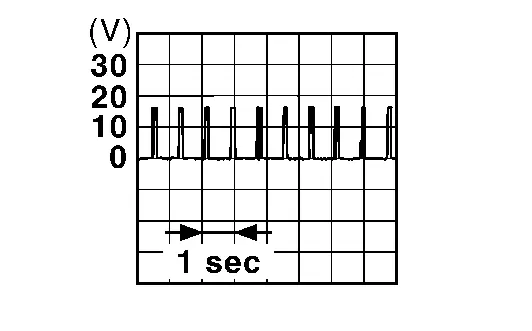
CHECK NATS ANTENNA AMP. COMMUNICATION SIGNAL
Check signal between push-button ignition switch harness connector and ground using an oscilloscope.
| (+) | (–) | Condition |
Signal (Reference value) | ||
|---|---|---|---|---|---|
| Push-button ignition switch | |||||
| Connector | Terminal | ||||
| M17 | 2 | Ground | Intelligent Key battery is removed and brake pedal is depressed | When a registered Intelligent Key backside is contacted to push-button ignition switch | 0 V |
| Other than above |
|
||||
| 3 | When a registered Intelligent Key backside is contacted to push-button ignition switch | 0 V | |||
| Other than above |
|
||||

Is the inspection result normal?
YES>>GO TO 3.
NO>>GO TO 2.
CHECK NATS ANTENNA AMP. COMMUNICATION SIGNAL CIRCUIT
-
Ignition switch OFF.
-
Disconnect Intelligent Key unit connector and push-button ignition switch connector.
-
Check continuity between push-button ignition switch harness connector and Intelligent Key unit harness connector.
Push-button ignition switch Intelligent Key unit Continuity Connector Terminal Connector Terminal M17 2 M38 19 Yes 3 20 -
Check continuity between push-button ignition switch harness connector and ground.
Push-button ignition switch (-) Continuity Connector Terminal M17 2 Ground No 3
Is the inspection result normal?
YES>>GO TO 3.
NO>>Repair or replace harness.
REPLACE PUSH-BUTTON IGNITION SWITCH
Replace push-button ignition switch. Refer to Removal and Installation.
Is the inspection result normal?
YES>>Inspection End.
NO>>GO TO 4.
REPLACE INTELLIGENT KEY UNIT
Replace Intelligent Key unit. Refer to Removal and Installation.
>>
Inspection End.
Hood Switch Nissan Pathfinder 2022
Component Function Check
CHECK FUNCTION
 CONSULT
-
Select “HOOD SW (CAN)” or “Hood switch” in “Data Monitor” mode of “IPDM E/R”.
-
Check “HOOD SW (CAN)” or “Hood switch” indication under the following condition.
| Monitor item | Condition | Indication |
|---|---|---|
| HOOD SW (CAN) | Close the hood | Close |
| Open the hood | Open | |
| Transmits invalid CAN signal | NG | |
| Hood switch | Close the hood | Close |
| Open the hood | Open |
Is the indication normal?
YES>>Hood switch is OK.
NO>>Refer to Diagnosis Procedure.
Diagnosis Procedure
CHECK HOOD SWITCH SIGNAL CIRCUIT 1
-
Ignition switch OFF.
-
Disconnect hood switch connector.
-
Check voltage between hood switch harness connector and ground.
| (+) | (–) |
Voltage (Approx.) | |
|---|---|---|---|
| Hood switch | |||
| Connector | Terminal | ||
| E234 | 1 | Ground | Battery voltage |
Is the inspection result normal?
YES>>GO TO 3.
NO>>GO TO 2.
CHECK HOOD SWITCH SIGNAL CIRCUIT 2
-
Disconnect IPDM E/R connector.
-
Check continuity between IPDM E/R harness connector and hood switch harness connector.
IPDM E/R Hood switch Continuity Connector Terminal Connector Terminal E217 52 E234 1 Yes -
Check continuity between IPDM E/R harness connector and ground.
IPDM E/R — Continuity Connector Terminal E217 52 Ground No
Is the inspection result normal?
YES>>Replace IPDM E/R. Refer to Removal and Installation.
NO>>Repair or replace harness.
CHECK HOOD SWITCH GROUND CIRCUIT
Check continuity between hood switch harness connector and ground.
| Hood switch | — | Continuity | |
|---|---|---|---|
| Connector | Terminal | ||
| E234 | 2 | Ground | Yes |
Is the inspection result normal?
YES>>GO TO 4.
NO>>Repair or replace harness.
CHECK HOOD SWITCH
Refer to Component Inspection.
Is the inspection result normal?
YES>>GO TO 5.
NO>>Replace hood lock assembly. Refer to Removal and Installation.
CHECK INTERMITTENT INCIDENT
Refer to Intermittent Incident.
>>
Inspection End.
Component Inspection
CHECK HOOD SWITCH
-
Ignition switch OFF.
-
Disconnect hood switch connector.
-
Check continuity between hood switch terminals.
Hood switch Condition Continuity Terminal 1 2 Hood lock Unlock condition No Lock condition Yes
Is the inspection result normal?
YES>>Inspection End.
NO>>Replace hood lock assembly. Refer to Removal and Installation.
Horn Function Nissan Pathfinder 2026
Component Function Check
CHECK FUNCTION
 CONSULT
-
Ignition switch OFF.
-
Perform “HORN” in “ACTIVE TEST” mode of “IPDM E/R”.
-
Check the horn operation.
Test item Description HORN On Horn Sounds (for 20 ms.)
Is the operation normal?
YES>>Inspection End.
NO>>Refer to Diagnosis Procedure (Horn (Low)) or Diagnosis Procedure (Horn (High)).
Diagnosis Procedure (Horn (Low))
CHECK HORN FUNCTION
Check horn function with horn switch.
Do horns sound?
YES>>GO TO 2.
NO>>Perform the trouble diagnosis for horn circuit. Refer to Wiring Diagram.
CHECK HORN RELAY CONTROL SIGNAL
 CONSULT
-
Ignition switch ON.
-
Select "HORN" in "ACTIVE TEST" mode of "IPDM E/R".
-
Check voltage between IPDM E/R harness connector and ground.
| (+) | (–) | Test item |
Voltage (Approx.) | ||
|---|---|---|---|---|---|
| IPDM E/R | |||||
| Connector | Terminal | ||||
| E119 | 9 | Ground | HORN | On | 0 V |
| Off | Battery voltage | ||||
Is operation normal?
YES>>GO TO 4.
NO>>GO TO 3.
CHECK IPDM E/R POWER SUPPLY CIRCUIT
-
Ignition switch OFF.
-
Disconnect horn relay-2 connector and IPDM E/R connector.
-
Check continuity between IPDM E/R harness connector and horn relay-2 harness connector.
IPDM E/R Horn relay-2 Continuity Connector Terminal Connector Terminal E119 9 E58 1 Yes -
Check continuity between IPDM E/R harness connector and ground.
IPDM E/R (–) Continuity Connector Terminal E119 9 Ground No
Is the inspection result normal?
YES>>GO TO 4.
NO>>Repair or replace harness.
CHECK INTERMITTENT INCIDENT
Refer to Intermittent Incident.
>>
Inspection End.
Diagnosis Procedure (Horn (High))
CHECK HORN FUNCTION
Check horn function with horn switch.
Do horns sound?
YES>>GO TO 2.
NO>>Perform the trouble diagnosis for horn circuit. Refer to Wiring Diagram.
CHECK HORN RELAY CONTROL SIGNAL
 CONSULT
-
Ignition switch ON.
-
Select "HORN" in "ACTIVE TEST" mode of "IPDM E/R".
-
Check voltage between IPDM E/R harness connector and ground.
| (+) | (–) | Test item |
Voltage (Approx.) | ||
|---|---|---|---|---|---|
| IPDM E/R | |||||
| Connector | Terminal | ||||
| E119 | 9 | Ground | HORN | On | 0 V |
| Off | Battery voltage | ||||
Is operation normal?
YES>>GO TO 4.
NO>>GO TO 3.
CHECK IPDM E/R POWER SUPPLY CIRCUIT
-
Ignition switch OFF.
-
Disconnect horn relay-1 connector and IPDM E/R connector.
-
Check continuity between IPDM E/R harness connector and horn relay-1 harness connector.
IPDM E/R Horn relay-1 Continuity Connector Terminal Connector Terminal E119 9 H-1 1 Yes -
Check continuity between IPDM E/R harness connector and ground.
IPDM E/R (–) Continuity Connector Terminal E119 9 Ground No
Is the inspection result normal?
YES>>GO TO 4.
NO>>Repair or replace harness.
CHECK INTERMITTENT INCIDENT
Refer to Intermittent Incident.
>>
Inspection End.
Starter Cut Relay Nissan Pathfinder R53
Component Inspection
CHECK STARTER CUT RELAY
-
Ignition switch OFF.
-
Disconnect starter cut relay.
-
Check continuity between starter cut relay terminals.
Starter cut relay Condition Continuity Terminal 8 7 12 V direct current supply between terminals 5 and 6 Yes No current supply No
Is the inspection result normal?
YES>>Inspection End.
NO>>Replace starter cut relay.
Stop Lamp Switch Nissan Pathfinder Fifth generation
Component Inspection
CHECK STOP LAMP SWITCH
-
Ignition switch OFF.
-
Disconnect stop lamp switch connector.
-
Check continuity between stop lamp switch terminals.
Stop lamp switch Condition Continuity Terminal 1 2 Brake pedal Not depressed No Depressed Yes
Is the inspection result normal?
YES>>Inspection End.
NO>>Replace stop lamp switch. Refer to Exploded View.
Brake Pedal Position Switch Nissan Pathfinder 2026
Component Inspection
CHECK BRAKE PEDAL POSITION SWITCH
-
Ignition switch OFF.
-
Disconnect stop lamp switch connector.
-
Check continuity between brake pedal position switch terminals.
Brake pedal position switch Condition Continuity Terminal 1 2 Brake pedal Not depressed No Depressed Yes
Is the inspection result normal?
YES>>Inspection End.
NO>>Replace brake pedal position switch. Refer to Exploded View.

Nissan Pathfinder (R53) 2022-2026 Service Manual
Dtc/circuit Diagnosis
- P161d-00 Immobilizer
- P161e-00 Immobilizer
- P161f-00 Immobilizer
- B2c20-12 Starter Control Relay
- B2c20-23 Starter Control Relay
- B2f70-01 Stop Lamp
- B2f71-23 Stop Lamp
- B2f72-23 Stop Lamp
- B2080 Power Switch
- B2033-4a Dongle Ng
- B2042-4a Electric Shift Authentication Fail
- B2043-4a Electric Shift Id Discord
- B2070-68 Key Registration
- B2090-14 Nats Antenna Amp.
- Hood Switch
- Horn Function
- Starter Cut Relay
- Stop Lamp Switch
- Brake Pedal Position Switch
Contact Us
Nissan Pathfinder Info Center
Email: info@nipathfinder.com
Phone: +1 (800) 123-4567
Address: 123 Pathfinder Blvd, Nashville, TN 37214, USA
Working Hours: Mon–Fri, 9:00 AM – 5:00 PM (EST)
