Nissan Pathfinder: Automatic Drive Positioner - Dtc/circuit Diagnosis
- B2900-01 Sliding / Lifting Switch
- B2920-09 Driver Seat Control Unit
- B2921-A2 Driver Seat Control Unit
- B2921-A3 Driver Seat Control Unit
- U2118-87 Can Comm Err (intelligent Key)
- Power Supply and Ground Circuit (driver Seat Control Unit)
- Sliding Switch
- Seat Memory Switch
- Power Seat Switch Lh Ground Circuit
- Sliding Sensor
- Tilt Sensor
- Sliding Motor
- Lifting Motor (front)
- Telescopic Motor
- Seat Memeory Switch Indicator
B2900-01 Sliding / Lifting Switch Nissan Pathfinder R53
DTC Description
DTC DETECTION LOGIC
| DTC No. |
CONSULT screen items (Trouble diagnosis content) | DTC detection condition | |
|---|---|---|---|
| B2900-01 |
Sliding / lifting switch (Sliding / lifting switch) |
Diagnosis condition | The power consumption control of driver seat control unit is in wake-up state |
| Signal (terminal) | Sliding / lifting switch signal (terminal #31) | ||
| Threshold | 0.352 – 3.962 V | ||
| Diagnosis delay time | 20 seconds or more | ||
POSSIBLE CAUSE
-
Sliding / lifting switch
-
Driver seat control unit
FAIL-SAFE
—
DTC CONFIRMATION PROCEDURE
PERFORM DTC CONFIRMATION PROCEDURE
 CONSULT
-
Ignition switch ON and wait for 20 seconds or more.
-
Select “Self Diagnostic Result” mode of “AUTO DRIVE POS.”.
Is DTC detected?
YES>>Refer to DTC Diagnosis Procedure.
NO>>To check malfunction symptom before repair: Refer to Intermittent Incident.
NO>>Confirmation after repair: Inspection End.
DTC Diagnosis Procedure
CHECK SLIDING / LIFTING SWITCH SIGNAL VOLTAGE
Check voltage between driver seat control unit harness connector and ground.
| (+) | (—) | Condition |
Voltage (Approx.) | ||
|---|---|---|---|---|---|
| Driver seat control unit | |||||
| Connector | Terminal | ||||
| B209 | 31 | Ground | Sliding switch | Operate (forward) | 3.065 – 3.962 V |
| Operate (backward) | 2.638 – 3.064 V | ||||
| Lifting switch | Operate (upward) | 0.789 – 1.755 V | |||
| Operate (downward) | 0.352 – 0.788 V | ||||
| Sliding / lifting switch release | 3.963 – 4.799 V* | ||||
*: When the power consumption control of driver seat control unit is in wake-up state.
Is the inspection result normal?
YES>>Inspection End.
NO>>GO TO 2.
CHECK SLIDING / LIFTING SWITCH
Check sliding / lifting switch. Refer to Component Inspection.
Is the inspection result normal?
YES>>Replace driver seat control unit. Refer to Removal and Installation.
NO>>Replace power seat switch LH. Refer to Removal and Installation.
Component Inspection
CHECK SLIDING / LIFTING SWITCH
-
Ignition switch OFF.
-
Disconnect power seat switch LH connector.
-
Check resistance between power seat switch LH terminals.
Power seat switch LH Condition Resistance: (kΩ) Terminals 1 4 Sliding switch Operate (forward) 4.485 – 4.575 Operate (backward) 2.673 – 2.727 Lifting switch Operate (upward) 0.418 – 0.426 Operate (downward) 0.258 – 0.264 Sliding / lifting switch release 29.700 – 30.300
Is the inspection result normal?
YES>>Inspection End.
NO>>Replace power seat switch LH. Refer to Removal and Installation.
B2920-09 Driver Seat Control Unit Nissan Pathfinder Fifth generation
DTC Description
DTC DETECTION LOGIC
| DTC No. |
CONSULT screen items (Trouble diagnosis content) | DTC detection condition | |
|---|---|---|---|
| B2920-09 |
Driver seat control unit (Driver seat control unit) |
Diagnosis condition | The power consumption control of driver seat control unit is in wake-up state |
| Signal (terminal) | — | ||
| Threshold | Detects internal relay fixing | ||
| Diagnosis delay time | 1 second or more | ||
POSSIBLE CAUSE
Driver seat control unit
FAIL-SAFE
—
DTC CONFIRMATION PROCEDURE
PERFORM DTC CONFIRMATION PROCEDURE
 CONSULT
-
Ignition switch ON.
-
Select “Self Diagnostic Result” mode of “AUTO DRIVE POS.”.
Is DTC detected?
YES>>Refer to DTC Diagnosis Procedure.
NO>>To check malfunction symptom before repair: Refer to Intermittent Incident.
NO>>Confirmation after repair: Inspection End.
DTC Diagnosis Procedure
REPLACE DRIVER SEAT CONTROL UNIT
Replace driver seat control unit. Refer to Removal and Installation.
>>
Inspection End.
B2921-A2 Driver Seat Control Unit Nissan Pathfinder
DTC Description
DTC DETECTION LOGIC
| DTC No. |
CONSULT screen items (Trouble diagnosis content) | DTC detection condition | |
|---|---|---|---|
| B2921-A2 |
Driver seat control unit (Driver seat control unit) |
Diagnosis condition | The power consumption control of driver seat control unit is in wake-up state |
| Signal (terminal) | Battery power supply (terminal #48) | ||
| Threshold | 8 V or less | ||
| Diagnosis delay time | 1 second or more | ||
POSSIBLE CAUSE
-
Fuse
-
Driver seat control unit battery power supply harness is open or shorted
-
Driver seat control unit
FAIL-SAFE
—
DTC CONFIRMATION PROCEDURE
PERFORM DTC CONFIRMATION PROCEDURE
 CONSULT
-
Ignition switch ON.
-
Select “Self Diagnostic Result” mode of “AUTO DRIVE POS.”.
Is DTC detected?
YES>>Refer to DTC Diagnosis Procedure.
NO>>To check malfunction symptom before repair: Refer to Intermittent Incident.
NO>>Confirmation after repair: Inspection End.
DTC Diagnosis Procedure
CHECK FUSE
-
Ignition switch OFF.
-
Check that the following fuse is not blown (open):
Signal name Fuse No. Capacity Battery power supply 54 20 A
Is the fuse blown (open)?
YES>>Replace the blown (open) fuse after repairing the affected circuit if a fuse is blown (open).
NO>>GO TO 2.
CHECK BATTERY POWER SUPPLY VOLTAGE
-
Disconnect driver seat control unit connector.
-
Check voltage between driver seat control unit harness connector and ground.
(+) (—) Voltage
(Approx.)Driver seat control unit Connector Terminal B210 48 Ground Battery voltage
Is the inspection result normal?
YES>>Replace driver seat control unit. Refer to Removal and Installation.
NO>>Repair the driver seat control unit battery power supply circuit.
B2921-A3 Driver Seat Control Unit Nissan Pathfinder 2026
DTC Description
DTC DETECTION LOGIC
| DTC No. |
CONSULT screen items (Trouble diagnosis content) | DTC detection condition | |
|---|---|---|---|
| B2921-A3 |
Driver seat control unit (Driver seat control unit) |
Diagnosis condition | The power consumption control of driver seat control unit is in wake-up state |
| Signal (terminal) | Battery power supply (terminal #48) | ||
| Threshold | 18 V or more | ||
| Diagnosis delay time | 1 second or more | ||
POSSIBLE CAUSE
Charging system
FAIL-SAFE
—
DTC CONFIRMATION PROCEDURE
PERFORM DTC CONFIRMATION PROCEDURE
 CONSULT
-
Ignition switch ON.
-
Select “Self Diagnostic Result” mode of “AUTO DRIVE POS.”.
Is DTC detected?
YES>>Refer to DTC Diagnosis Procedure.
NO>>To check malfunction symptom before repair: Refer to Intermittent Incident.
NO>>Confirmation after repair: Inspection End.
DTC Diagnosis Procedure
CHECK CHARGING SYSTEM
Perform trouble diagnosis for charging system. Refer to Work Flow (With 165-DSS-5000P) or Work Flow (Without 165-DSS-5000P).
>>
Inspection End.
U2118-87 Can Comm Err (intelligent Key) Nissan Pathfinder R53
DTC Description
CAN (Controller Area Network) is a serial communication line for real time applications. It is an on-Nissan Pathfinder vehicle multiplex communication line with high data communication speed and excellent error detection ability. Modern Nissan Pathfinder vehicle is equipped with many electronic control unit, and each control unit shares information and links with other control units during operation (not independent). In CAN communication, control units are connected with 2 communication lines (CAN-High line, CAN-Low line) allowing a high rate of information transmission with less wiring. Each control unit transmits/receives data but selectively reads required data only.
DTC DETECTION LOGIC
| DTC No. |
CONSULT screen items (Trouble diagnosis content) | DTC detection condition | |
|---|---|---|---|
| U2118-87 |
CAN comm err (Intelligent Key) [Controller area network communication error (Intelligent Key)] |
Diagnosis condition | When ignition switch is ON |
| Signal (terminal) | CAN communication signal | ||
| Threshold | When driver seat control unit cannot communicate CAN communication signal | ||
| Diagnosis delay time | 2 seconds or more | ||
POSSIBLE CAUSE
CAN communication system
FAIL-SAFE
—
DTC CONFIRMATION PROCEDURE
PERFORM DTC CONFIRMATION PROCEDURE
 CONSULT
-
Ignition switch ON and wait for 2 seconds or more.
-
Select “Self Diagnostic Result” mode of “AUTO DRIVE POS.”.
Is DTC detected?
YES>>Refer to DTC Diagnosis Procedure.
NO>>To check malfunction symptom before repair: Refer to Intermittent Incident.
NO>>Confirmation after repair: Inspection End.
DTC Diagnosis Procedure
CHECK CAN COMMUNICATION SYSTEM
Perform trouble diagnosis for CAN communication system. Refer to Trouble Diagnosis Flow Chart.
>>
Inspection End.
Power Supply and Ground Circuit (driver Seat Control Unit) Nissan Pathfinder 2026
Diagnosis Procedure
CHECK FUSE
-
Ignition switch OFF.
-
Check that the following fuse is not blown (open):
Signal name Fuse No. Capacity Battery power supply 54 20 A
Is the fuse blown (open)?
YES>>Replace the blown (open) fuse after repairing the affected circuit if a fuse is blown (open).
NO>>GO TO 2.
CHECK BATTERY POWER SUPPLY VOLTAGE
-
Disconnect driver seat control unit connector.
-
Check voltage between driver seat control unit harness connector and ground.
(+) (—) Voltage
(Approx.)Driver seat control unit Connector Terminal B210 48 Ground Battery voltage
Is the inspection result normal?
YES>>GO TO 3.
NO>>Repair the driver seat control unit battery power supply circuit.
CHECK GROUND CIRCUIT (OPEN)
Check continuity between driver seat control unit harness connector and ground.
| Driver seat control unit | — | Continuity | |
|---|---|---|---|
| Connector | Terminal | ||
| B210 | 51 | Ground | Yes |
Is the inspection result normal?
YES>>Inspection End.
NO>>Repair the harness or connector.
Sliding Switch Nissan Pathfinder 5th Gen
Component Function Check
CHECK FUNCTION
 CONSULT
-
Ignition switch ON.
-
Select “Sliding switch (Forward)” and “Sliding switch (Backward)” in “Data Monitor” mode of “AUTO DRIVE POS.”.
-
Check sliding switch signal under the following conditions:
| Monitor item | Condition | Status | |
|---|---|---|---|
| Sliding switch (Forward) | Sliding switch | Operate (forward) | On |
| Release | Off | ||
| Sliding switch (Backward) | Sliding switch | Operate (backward) | On |
| Release | Off | ||
Is the inspection result normal?
YES>>Inspection End.
NO>>Refer to Diagnosis Procedure.
Diagnosis Procedure
CHECK SLIDING SWITCH POWER SUPPLY VOLTAGE
-
Ignition switch OFF.
-
Disconnect power seat switch LH connector.
-
Ignition switch ON.
-
Check voltage between power seat switch LH harness connector and ground.
(+) (—) Voltage
(Approx.)Power seat switch LH Connector Terminal B208 4 Ground 5 V
Is the inspection result normal?
YES>>GO TO 4.
NO>>GO TO 2.
CHECK SLIDING SWITCH SIGNAL CIRCUIT (OPEN)
-
Ignition switch OFF.
-
Disconnect driver seat control unit connector.
-
Check continuity between power seat switch LH harness connector and driver seat control unit harness connector.
Power seat switch LH Driver seat control unit Continuity Connector Terminal Connector Terminal B208 4 B209 31 Yes
Is the inspection result normal?
YES>>GO TO 3.
NO>>Repair the harness or connector.
CHECK SLIDING SWITCH SIGNAL CIRCUIT (SHORT TO GROUND)
Check continuity between power seat switch LH harness connector and ground.
| Power seat switch LH | — | Continuity | |
|---|---|---|---|
| Connector | Terminal | ||
| B208 | 4 | Ground | No |
Is the inspection result normal?
YES>>Replace driver seat control unit. Refer to Removal and Installation.
NO>>Repair the harness or connector.
CHECK SLIDING SWITCH
Check sliding switch. Refer to Component Inspection.
Is the inspection result normal?
YES>>Inspection End.
NO>>Replace power seat switch LH. Refer to Removal and Installation.
Component Inspection
CHECK SLIDING SWITCH
-
Ignition switch OFF.
-
Disconnect power seat switch LH connector.
-
Check resistance between power seat switch LH terminals.
Power seat switch LH Condition Resistance (kΩ) Terminals 1 4 Sliding switch Operate (forward) 4.485 – 4.575 Operate (backward) 2.673 – 2.727 Release 29.700 – 30.300
Is the inspection result normal?
YES>>Inspection End.
NO>>Replace power seat switch LH. Refer to Removal and Installation.
Seat Memory Switch Nissan Pathfinder 2026
Component Function Check
CHECK FUNCTION
 CONSULT
-
Ignition switch ON.
-
Select “Memory switch 1”, “Memory switch 2” and “Set switch” in “Data Monitor” mode of “AUTO DRIVE POS.”.
-
Check seat memory switch signal under the following conditions:
| Monitor item | Condition | Status | |
|---|---|---|---|
| Memory switch 1 | Memory switch-1 | Press | On |
| Release | Off | ||
| Memory switch 2 | Memory switch-2 | Press | On |
| Release | Off | ||
| Set switch | Set switch | Press | On |
| Release | Off | ||
Is the inspection result normal?
YES>>Inspection End.
NO>>Refer to Diagnosis Procedure.
Diagnosis Procedure
CHECK SEAT MEMORY SWITCH POWER SUPPLY VOLTAGE
-
Ignition switch OFF.
-
Disconnect seat memory switch connector.
-
Ignition switch ON.
-
Check voltage between seat memory switch harness connector and ground.
(+) (—) Voltage
(Approx.)Seat memory switch Connector Terminal D60 1 Ground Battery voltage 6 7
Is the inspection result normal?
YES>>GO TO 4.
NO>>GO TO 2.
CHECK SEAT MEMORY SWITCH SIGNAL CIRCUIT (OPEN)
-
Ignition switch OFF.
-
Disconnect driver seat control unit connector.
-
Check continuity between seat memory switch harness connector and driver seat control unit harness connector.
Seat memory switch Driver seat control unit Continuity Connector Terminal Connector Terminal D60 1 B209 10 Yes 6 12 7 9
Is the inspection result normal?
YES>>GO TO 3.
NO>>Repair the harness or connector.
CHECK SEAT MEMORY SWITCH SIGNAL CIRCUIT (SHORT TO GROUND)
Check continuity between seat memory switch harness connector and ground.
| Seat memory switch | — | Continuity | |
|---|---|---|---|
| Connector | Terminal | ||
| D60 | 1 | Ground | No |
| 6 | |||
| 7 | |||
Is the inspection result normal?
YES>>Replace driver seat control unit. Refer to Removal and Installation.
NO>>Repair the harness or connector.
CHECK SEAT MEMORY SWITCH GROUND CIRCUIT (OPEN)
-
Ignition switch OFF.
-
Check continuity between seat memory switch harness connector and ground.
Seat memory switch — Continuity Connector Terminal D60 8 Ground Yes
Is the inspection result normal?
YES>>GO TO 5.
NO>>Repair the harness or connector.
CHECK SEAT MEMORY SWITCH
Check seat memory switch. Refer to Component Inspection.
Is the inspection result normal?
YES>>Inspection End.
NO>>Replace seat memory switch. Refer to Removal and Installation.
Component Inspection
CHECK SEAT MEMORY SWITCH
-
Ignition switch OFF.
-
Disconnect seat memory switch connector.
-
Check continuity between seat memory switch terminals.
Seat memory switch Condition Continuity Terminals 8 7 Memory switch-1 Press Yes Release No 1 Memory switch-2 Press Yes Release No 6 Set switch Press Yes Release No
Is the inspection result normal?
YES>>Inspection End.
NO>>Replace seat memory switch. Refer to Removal and Installation.
Power Seat Switch Lh Ground Circuit Nissan Pathfinder R53
Diagnosis Procedure
CHECK POWER SEAT SWITCH GROUND CIRCUIT (OPEN)
-
Ignition switch OFF.
-
Disconnect power seat switch LH connector and driver seat control unit connector.
-
Check continuity between power seat switch LH harness connector and driver seat control unit harness connector.
Power seat switch LH Driver seat control unit Continuity Connector Terminal Connector Terminal B208 1 B209 32 Yes
Is the inspection result normal?
YES>>Inspection End.
NO>>Repair the harness or connector.
Sliding Sensor Nissan Pathfinder SUV
Component Function Check
CHECK FUNCTION
 CONSULT
-
Ignition switch ON.
-
Select “Sliding motor position” in “Data Monitor” mode of “AUTO DRIVE POS.”.
-
Check sliding sensor signal under the following conditions:
| Monitor item | Condition | Status | |
|---|---|---|---|
| Sliding motor position | Seat sliding | Operate (forward) | Change (increase) |
| Operate (backward) | Change (decrease) | ||
| Other than the above | No change | ||
Is the inspection result normal?
YES>>Inspection End.
NO>>Refer to Diagnosis Procedure.
Diagnosis Procedure
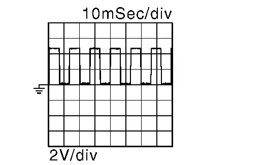
CHECK SLIDING SENSOR SIGNAL
Check signal between driver seat control unit harness connector and ground with oscilloscope.
| (+) | (—) | Condition |
Signal (Reference value) | ||
|---|---|---|---|---|---|
| Driver seat control unit | |||||
| Connector | Terminal | ||||
| B209 | 35 | Ground | Seat sliding | Operate |
|
| Other than the above | 5 V* | ||||

*: When the power consumption control of driver seat control unit is in wake-up state.
Is the inspection result normal?
YES>>Replace driver seat control unit. Refer to Removal and Installation.
NO>>GO TO 2.
CHECK SLIDING SENSOR SIGNAL CIRCUIT (OPEN)
-
Ignition switch OFF.
-
Disconnect driver seat control unit connector and sliding motor LH connector.
-
Check continuity between driver seat control unit harness connector and sliding motor LH harness connector.
Driver seat control unit Sliding motor LH Continuity Connector Terminal Connector Terminal B209 35 B211 3 Yes
Is the inspection result normal?
YES>>GO TO 3.
NO>>Repair the harness or connector.
CHECK SLIDING SENSOR SIGNAL CIRCUIT (SHORT TO GROUND)
Check continuity between driver seat control unit harness connector and ground.
| Driver seat control unit | — | Continuity | |
|---|---|---|---|
| Connector | Terminal | ||
| B209 | 35 | Ground | No |
Is the inspection result normal?
YES>>GO TO 4.
NO>>Repair the harness or connector.
CHECK SLIDING SENSOR POWER SUPPLY VOLTAGE
-
Connect driver seat control unit connector.
-
Check voltage between sliding motor LH harness connector and ground.
(+) (—) Voltage
(Approx.)Sliding motor LH Connector Terminal B211 4 Ground Battery voltage
Is the inspection result normal?
YES>>GO TO 7.
NO>>GO TO 5.
CHECK SLIDING SENSOR POWER SUPPLY CIRCUIT (OPEN)
-
Disconnect driver seat control unit connector.
-
Check continuity between sliding motor LH harness connector and driver seat control unit harness connector.
Sliding motor LH Driver seat control unit Continuity Connector Terminal Connector Terminal B211 4 B209 34 Yes
Is the inspection result normal?
YES>>GO TO 6.
NO>>Repair the harness or connector.
CHECK SLIDING SENSOR POWER SUPPLY CIRCUIT (SHORT TO GROUND)
Check continuity between sliding motor LH harness connector and ground.
| Sliding motor LH | — | Continuity | |
|---|---|---|---|
| Connector | Terminal | ||
| B211 | 4 | Ground | No |
Is the inspection result normal?
YES>>Replace driver seat control unit. Refer to Removal and Installation.
NO>>Repair the harness or connector.
CHECK SLIDING SENSOR GROUND CIRCUIT (OPEN)
-
Disconnect driver seat control unit connector.
-
Check continuity between sliding motor LH harness connector and driver seat control unit harness connector.
Sliding motor LH Driver seat control unit Continuity Connector Terminal Connector Terminal B211 2 B209 33 Yes
Is the inspection result normal?
YES>>Replace sliding motor LH.
NO>>Repair the harness or connector.
Tilt Sensor Nissan Pathfinder 2022
Component Function Check
CHECK FUNCTION
 CONSULT
-
Ignition switch ON.
-
Select “TILT PULSE” in “Data Monitor” mode of “AUTO DRIVE POS.”.
-
Check sliding tilt signal under the following conditions:
| Monitor item | Condition | Status | |
|---|---|---|---|
| TILT PULSE | Tilt motor | Operate (upward) | Change (increase) |
| Operate (downward) | Change (decrease) | ||
| Other than the above | No change | ||
Is the inspection result normal?
YES>>Inspection End.
NO>>Refer to Diagnosis Procedure.
Diagnosis Procedure
CHECK TILT SENSOR SIGNAL
Check signal between automatic drive positioner control unit harness connector and ground with oscilloscope.
| (+) | (—) | Condition |
Signal (Reference value) | ||
|---|---|---|---|---|---|
| Automatic drive positioner control unit | |||||
| Connector | Terminal | ||||
| M33 | 7 | Ground | Steering tilt | Operate |
|
| Other than the above | 5 V* | ||||
*: When the power consumption control of automatic drive positioner control unit is in wake-up state.
Is the inspection result normal?
YES>>Replace automatic drive positioner control unit. Refer to Removal and Installation.
NO>>GO TO 2.
CHECK TILT SENSOR SIGNAL CIRCUIT (OPEN)
-
Ignition switch OFF.
-
Disconnect automatic drive positioner control unit connector and tilt motor connector.
-
Check continuity between automatic drive positioner control unit harness connector and tilt motor harness connector.
Automatic drive positioner control unit Tilt motor Continuity Connector Terminal Connector Terminal M33 7 M85 5 Yes
Is the inspection result normal?
YES>>GO TO 3.
NO>>Repair the harness or connector.
CHECK TILT SENSOR SIGNAL CIRCUIT (SHORT TO GROUND)
Check continuity between automatic drive positioner control unit harness connector and ground.
| Automatic drive positioner control unit | — | Continuity | |
|---|---|---|---|
| Connector | Terminal | ||
| M33 | 7 | Ground | No |
Is the inspection result normal?
YES>>GO TO 4.
NO>>Repair the harness or connector.
CHECK TILT SENSOR POWER SUPPLY VOLTAGE
-
Connect automatic drive positioner control unit connector.
-
Check voltage between tilt motor harness connector and ground.
(+) (—) Voltage
(Approx.)Tilt motor Connector Terminal M85 4 Ground Battery voltage
Is the inspection result normal?
YES>>GO TO 7.
NO>>GO TO 5.
CHECK TILT SENSOR POWER SUPPLY CIRCUIT (OPEN)
-
Disconnect automatic drive positioner control unit connector.
-
Check continuity between tilt motor harness connector and automatic drive positioner control unit harness connector.
Tilt motor Automatic drive positioner control unit Continuity Connector Terminal Connector Terminal M85 4 M33 8 Yes
Is the inspection result normal?
YES>>GO TO 6.
NO>>Repair the harness or connector.
CHECK TILT SENSOR POWER SUPPLY CIRCUIT (SHORT TO GROUND)
Check continuity between tilt motor harness connector and ground.
| Tilt motor | — | Continuity | |
|---|---|---|---|
| Connector | Terminal | ||
| M85 | 4 | Ground | No |
Is the inspection result normal?
YES>>Replace automatic drive positioner control unit. Refer to Removal and Installation.
NO>>Repair the harness or connector.
CHECK TILT SENSOR GROUND CIRCUIT (OPEN)
-
Disconnect automatic drive positioner control unit connector.
-
Check continuity between tilt motor harness connector and automatic drive positioner control unit harness connector.
Tilt motor Automatic drive positioner control unit Continuity Connector Terminal Connector Terminal M85 6 M33 9 Yes
Is the inspection result normal?
YES>>Replace tilt motor. Refer to Removal and Installation.
NO>>Repair the harness or connector.
Sliding Motor Nissan Pathfinder 2026
Component Function Check
CHECK FUNCTION
 CONSULT
-
Ignition switch ON.
-
Select “Sliding motor” in “Active Test” mode of “AUTO DRIVE POS.”.
-
Check sliding motor operation.
| Test item | Operation | ||
|---|---|---|---|
| Sliding motor | Forward | Seat sliding | Forward |
| Backward | Backward | ||
| Stop | Stop | ||
Is the inspection result normal?
YES>>Inspection End.
NO>>Refer to Diagnosis Procedure.
Diagnosis Procedure
CHECK SLIDING MOTOR POWER SUPPLY VOLTAGE
 CONSULT
-
Ignition switch OFF.
-
Disconnect sliding motor LH connector.
-
Ignition switch ON.
-
Select “Sliding motor” in “Active Test” mode of “AUTO DRIVE POS.”.
-
Check voltage between sliding motor LH harness connector and ground.
(+) (—) Condition Voltage
(Approx.)Sliding motor LH Connector Terminal B211 5 Ground Sliding motor Forward Battery voltage Backward 0 V Stop 0 V 1 Forward 0 V Backward Battery voltage Stop 0 V
Is the inspection result normal?
YES>>Replace sliding motor LH.
NO>>GO TO 2.
CHECK SLIDING MOTOR POWER SUPPLY CIRCUIT (OPEN)
-
Ignition switch OFF.
-
Disconnect driver seat control unit connector.
-
Check continuity between sliding motor LH harness connector and driver seat control unit harness connector.
Sliding motor LH Driver seat control unit Continuity Connector Terminal Connector Terminal B211 1 B210 44 Yes 5 43
Is the inspection result normal?
YES>>GO TO 3.
NO>>Repair the harness or connector.
CHECK SLIDING MOTOR POWER SUPPLY CIRCUIT (SHORT TO GROUND)
Check continuity between sliding motor LH harness connector and ground.
| Sliding motor LH | — | Continuity | |
|---|---|---|---|
| Connector | Terminal | ||
| B211 | 1 | Ground | No |
| 5 | |||
Is the inspection result normal?
YES>>Replace driver seat control unit. Refer to Removal and Installation.
NO>>Repair the harness or connector.
Lifting Motor (front) Nissan Pathfinder SUV
Component Function Check
CHECK FUNCTION
 CONSULT
-
Ignition switch ON.
-
Select “SEAT LIFTER FR” in “Active Test” mode of “AUTO DRIVE POS.”.
-
Check lifting motor LH (front) operation.
| Test item | Operation | ||
|---|---|---|---|
| SEAT LIFTER FR | Up | Lifting motor LH (front) | Upward |
| Down | Downward | ||
| Stop | Stop | ||
Is the inspection result normal?
YES>>Inspection End.
NO>>Refer to Diagnosis Procedure.
Diagnosis Procedure
CHECK LIFTING MOTOR LH (FRONT) POWER SUPPLY VOLTAGE
 CONSULT
-
Ignition switch OFF.
-
Disconnect lifting motor LH (front) connector.
-
Ignition switch ON.
-
Select “SEAT LIFTER FR” in “Active Test” mode of “AUTO DRIVE POS.”.
-
Check voltage between lifting motor LH (front) harness connector and ground.
(+) (—) Condition Voltage
(Approx.)Lifting motor LH (front) Connector Terminal B202 1 Ground Lifting motor LH (front) Up Battery voltage Down 0 V Stop 0 V 3 Up 0 V Down Battery voltage Stop 0 V
Is the inspection result normal?
YES>>Replace seat cushion frame. Refer to Seat Cushion.
NO>>GO TO 2.
CHECK LIFTING MOTOR LH (FRONT) POWER SUPPLY CIRCUIT (OPEN)
-
Ignition switch OFF.
-
Disconnect driver seat control unit connector.
-
Check continuity between lifting motor LH (front) harness connector and driver seat control unit harness connector.
Lifting motor LH (front) Driver seat control unit Continuity Connector Terminal Connector Terminal B202 1 B210 53 Yes 3 52
Is the inspection result normal?
YES>>GO TO 3.
NO>>Repair the harness or connector.
CHECK LIFTING MOTOR LH (FRONT) POWER SUPPLY CIRCUIT (SHORT TO GROUND)
Check continuity between lifting motor LH (front) harness connector and ground.
| Lifting motor LH (front) | — | Continuity | |
|---|---|---|---|
| Connector | Terminal | ||
| B202 | 1 | Ground | No |
| 3 | |||
Is the inspection result normal?
YES>>Replace driver seat control unit. Refer to Removal and Installation.
NO>>Repair the harness or connector.
Telescopic Motor Nissan Pathfinder Fifth generation
Component Function Check
CHECK FUNCTION
 CONSULT
-
Ignition switch ON.
-
Select “TELESCO MOTOR” in “Active Test” mode of “AUTO DRIVE POS.”.
-
Check telescopic motor operation.
| Test item | Operation | ||
|---|---|---|---|
| TELESCO MOTOR | FR | Steering telescopic | Forward |
| RR | Backward | ||
| Off | Off | ||
Is the inspection result normal?
YES>>Inspection End.
NO>>Refer to Diagnosis Procedure.
Diagnosis Procedure
CHECK TELESCOPIC MOTOR POWER SUPPLY VOLTAGE
 CONSULT
-
Ignition switch OFF.
-
Disconnect telescopic motor connector.
-
Ignition switch ON.
-
Select “TELESCOPIC MOTOR” in “Active Test” mode of “AUTO DRIVE POS.”.
-
Check voltage between telescopic motor harness connector and ground.
(+) (—) Condition Voltage
(Approx.)Telescopic motor Connector Terminal M94 2 Ground Telescopic motor Forward Battery voltage Backward 0 V Stop 0 V 1 Forward 0 V Backward Battery voltage Stop 0 V
Is the inspection result normal?
YES>>Replace telescopic motor.
NO>>GO TO 2.
CHECK TELESCOPIC MOTOR POWER SUPPLY CIRCUIT (OPEN)
-
Ignition switch OFF.
-
Disconnect automatic drive positioner control unit connector.
-
Check continuity between telescopic motor harness connector and automatic drive positioner control unit harness connector.
Telescopic motor Automatic drive positioner control unit Continuity Connector Terminal Connector Terminal M94 1 M34 17 Yes 2 18
Is the inspection result normal?
YES>>GO TO 3.
NO>>Repair the harness or connector.
CHECK TELESCOPIC MOTOR POWER SUPPLY CIRCUIT (SHORT TO GROUND)
Check continuity between telescopic motor harness connector and ground.
| Telescopic motor | — | Continuity | |
|---|---|---|---|
| Connector | Terminal | ||
| M94 | 1 | Ground | No |
| 2 | |||
Is the inspection result normal?
YES>>Replace automatic drive positioner control unit. Refer to Removal and Installation.
NO>>Repair the harness or connector.
Seat Memeory Switch Indicator Nissan Pathfinder
Component Function Check
CHECK FUNCTION
-
Push set switch.
-
Check memory indicator operation.
When driver seat position is already retained in memory : Illuminated for 5 seconds When driver seat position is not retained in memory : Illuminated for 0.5 second
Is the inspection result normal?
YES>>Inspection End.
NO>>Refer to Diagnosis Procedure.
Diagnosis Procedure
CHECK MEMORY INDICATOR OPERATION
Check memory indicator operation.
Which is the malfunctioning indicator?
All indicators are NG>>GO TO 2.
An indicator is NG>>GO TO 4.
CHECK FUSE
Check that the following fuse is not blown (open):
| Signal name | Fuse No. | Capacity |
|---|---|---|
| Memory indicator power supply | 26 | 5 A |
Is the fuse blown (open)?
YES>>Replace the blown (open) fuse after repairing the affected circuit if a fuse is blown (open).
NO>>GO TO 3.
CHECK MEMORY INDICATOR POWER SUPPLY VOLTAGE
-
Disconnect seat memory switch connector.
-
Check voltage between seat memory switch harness connector and ground.
(+) (—) Voltage
(Approx.)Seat memory switch Connector Terminal D60 2 Ground Battery voltage
Is the inspection result normal?
YES>>Replace seat memory switch. Refer to Removal and Installation.
NO>>Repair the memory indicator power supply circuit.
CHECK MEMORY INDICATOR SIGNAL VOLTAGE
Check voltage between seat memory switch harness connector and ground.
| (+) | (—) |
Voltage (Approx.) | |
|---|---|---|---|
| Seat memory switch | |||
| Connector | Terminal | ||
| D60 | 3 | Ground | Battery voltage |
| 4 | |||
Is the inspection result normal?
YES>>GO TO 5.
NO>>Replace seat memory switch. Refer to Removal and Installation.
CHECK MEMORY INDICATOR SIGNAL CIRCUIT (OPEN)
-
Disconnect seat memory switch connector and driver seat control unit connector.
-
Check continuity between seat memory switch harness connector and driver seat control unit harness connector.
Seat memory switch Driver seat control unit Continuity Connector Terminal Connector Terminal D60 3 B209 38 Yes 4 18
Is the inspection result normal?
YES>>GO TO 6.
NO>>Repair the harness or connector.
CHECK MEMORY INDICATOR SIGNAL CIRCUIT (SHORT TO GROUND)
Check continuity between seat memory switch harness connector and ground.
| Seat memory switch | — | Continuity | |
|---|---|---|---|
| Connector | Terminal | ||
| D60 | 3 | Ground | No |
| 4 | |||
Is the inspection result normal?
YES>>Replace driver seat control unit. Refer to Removal and Installation.
NO>>Repair the harness or connector.

Nissan Pathfinder (R53) 2022-2026 Service Manual
Dtc/circuit Diagnosis
- B2900-01 Sliding / Lifting Switch
- B2920-09 Driver Seat Control Unit
- B2921-A2 Driver Seat Control Unit
- B2921-A3 Driver Seat Control Unit
- U2118-87 Can Comm Err (intelligent Key)
- Power Supply and Ground Circuit (driver Seat Control Unit)
- Sliding Switch
- Seat Memory Switch
- Power Seat Switch Lh Ground Circuit
- Sliding Sensor
- Tilt Sensor
- Sliding Motor
- Lifting Motor (front)
- Telescopic Motor
- Seat Memeory Switch Indicator
Contact Us
Nissan Pathfinder Info Center
Email: info@nipathfinder.com
Phone: +1 (800) 123-4567
Address: 123 Pathfinder Blvd, Nashville, TN 37214, USA
Working Hours: Mon–Fri, 9:00 AM – 5:00 PM (EST)
