Nissan Pathfinder: System Description - Component Parts ++
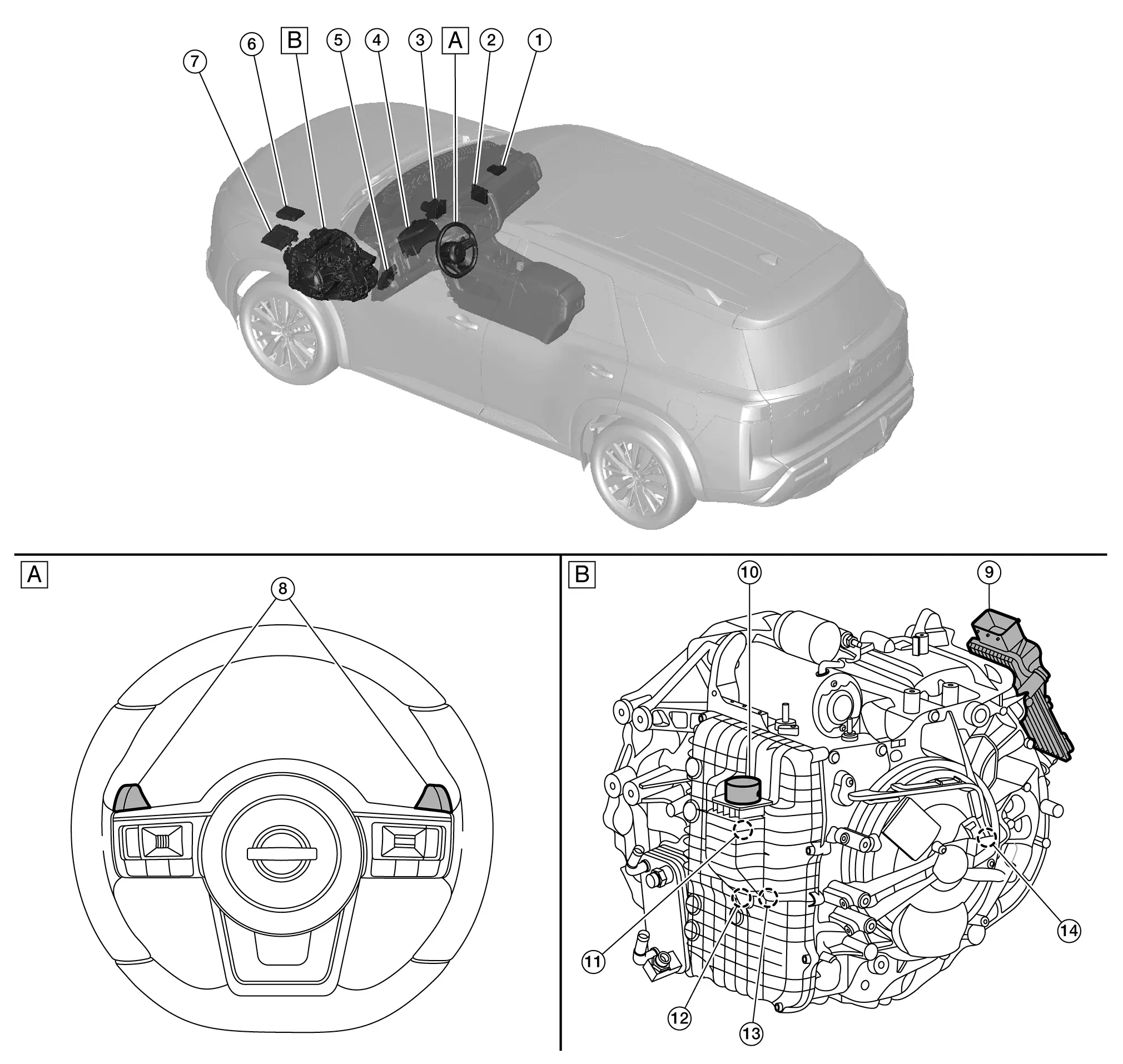
A/t Control System Component Parts Location
 |
Intelligent Key unit |  |
A/C auto amp |  |
ABS actuator and electric unit (control unit) Refer to Component Parts Location. |
 |
Combination meter Refer to Removal and Installation. |
 |
BCM Refer to Component Parts Location. |
 |
IPDM E/R |
 |
ECM Refer to Component Parts Location. |
 |
Paddle shifter |  |
TCM |
 |
A/T unit connector |  |
Control valve |  |
Dog clutch F position sensor |
 |
Sensor unit |  |
Dog clutch A position sensor | ||
 |
Steering wheel |  |
Side of transaxle assembly |
TCM
FUNCTIONS WITHIN THE SYSTEM
-
A/T is perfectly controlled depending on the driving condition which is judged by the signals from each sensor, switch and the other control units.
-
Self diagnosis system is available for easy trouble diagnosis.
-
Fail-safe function is available for system error.
INDIVIDUAL FUNCTION WITHIN SYSTEM
TCM mainly consists of the following functions.
-
" Input interface" performs to input signals from each sensor.
-
"Arithmetic circuit" gets the control target value through arithmetic processing by comparing with recorded program.
-
"Output interface" converts the control target value to the actuator control signal.
-
"Power circuit" makes TCM, sensor and actuator function.
INDIVIDUAL OPERATION
TCM controls A/T system.
COMPONENT PARTS LOCATION
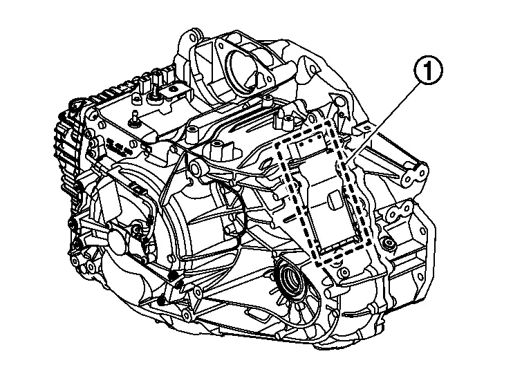
TCM  is installed on the transaxle assembly.
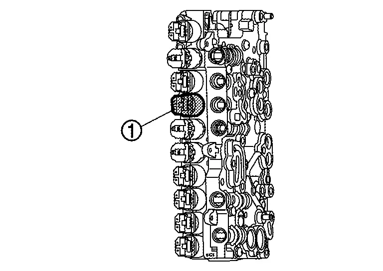
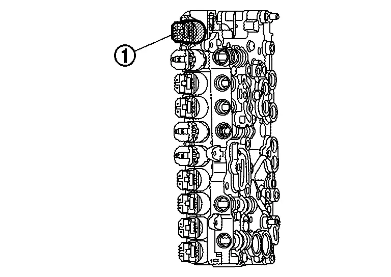
A/T Fluid Temperature Sensor
FUNCTIONS WITHIN THE SYSTEM
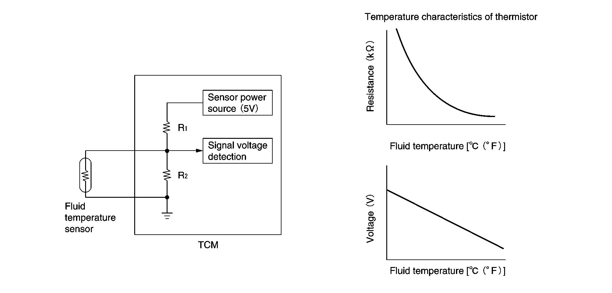
A/T fluid temperature sensor transfers detected fluid temperature to TCM as voltage signal.
INDIVIDUAL FUNCTION WITHIN SYSTEM
A/T fluid temperature sensor detects A/T fluid temperature.
INDIVIDUAL OPERATION
The fluid temperature sensor uses a thermistor, and changes the voltage signal by converting changes in the A/T fluid temperature to a resistance value.
The voltage signal value change must be in proportion to the resistance value change.
TCM evaluates the A/T fluid temperature from the voltage signal value.
COMPONENT PARTS LOCATION
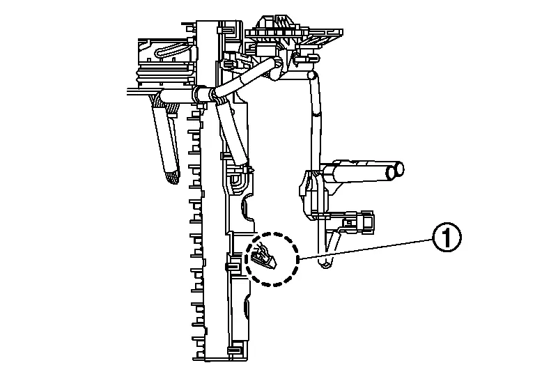
A/T fluid temperature sensor  is built into the sensor unit.
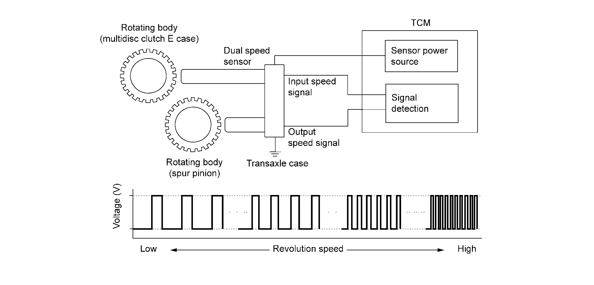
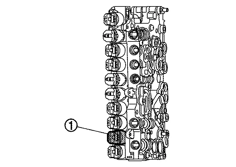
Dual Speed Sensor
FUNCTIONS WITHIN THE SYSTEM
Dual speed sensor transfers detected revolution speed of the input shaft (multidisc clutch E case) and the spur pinion to TCM as pulse signal.
INDIVIDUAL FUNCTION WITHIN SYSTEM
Dual speed sensor transfers detected revolution speed of the input shaft (multidisc clutch E case) and the spur pinion.
INDIVIDUAL OPERATION
The dual speed sensor generates an ON-OFF pulse signal according to the speed of each rotating body.
TCM judges the each rotating body speed based on the each pulse signal.
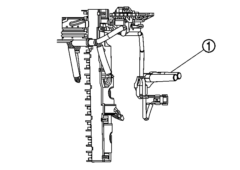
COMPONENT PARTS LOCATION
Dual speed sensor  is installed inside the transaxle assembly.
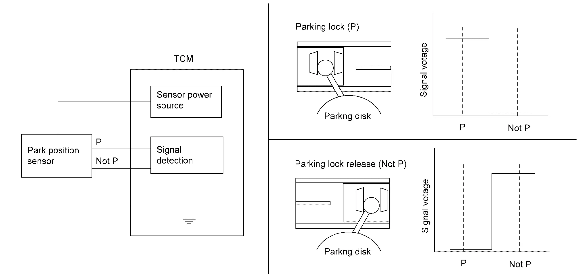
Park Position Sensor
FUNCTIONS WITHIN THE SYSTEM
Park position sensor transfers detected shift position (not P or P) to TCM as voltage signal.
INDIVIDUAL FUNCTION WITHIN SYSTEM
Park position sensor transfers detected shift position (not P or P).
INDIVIDUAL OPERATION
Park position sensor detects the shift position (not P or P) depending on the position of the slider on the park position sensor.
The slider is linked to the movement of the park disc. Refer to System Description for the movement of the parking disk.
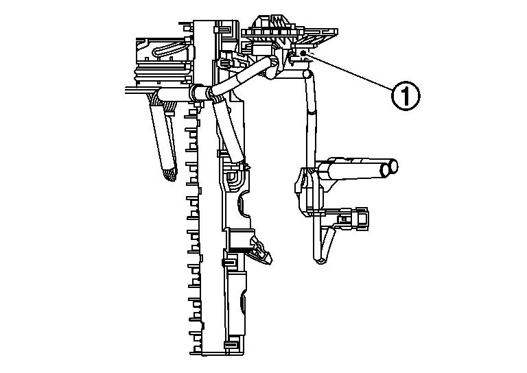
COMPONENT PARTS LOCATION
Park position sensor  is installed inside the transaxle assembly.
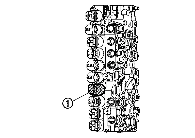
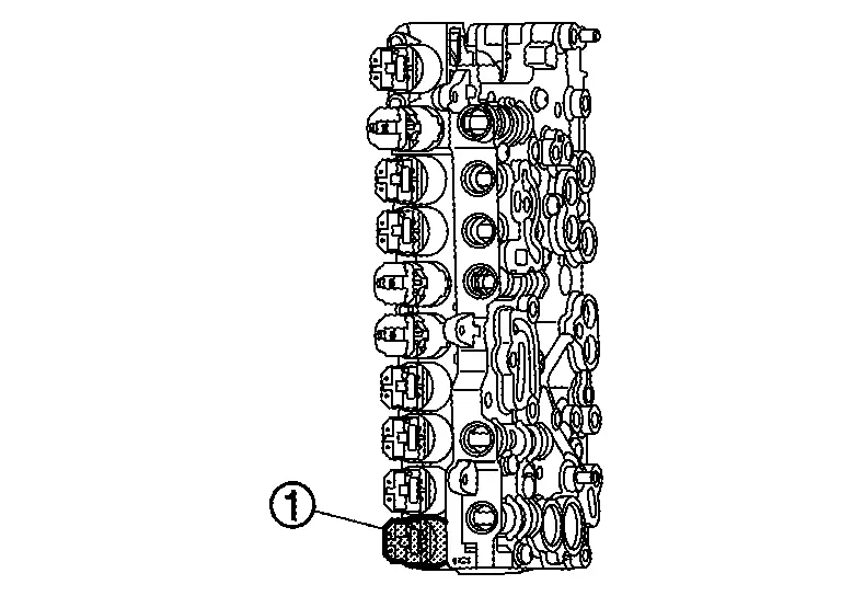
Dog Clutch A Position Sensor
FUNCTIONS WITHIN THE SYSTEM
Dog clutch A position sensor transfers current position – open or engaged – of the dog clutch A to TCM as PWM signal.
INDIVIDUAL FUNCTION WITHIN SYSTEM
Dog clutch A position sensor transfers current position – open or engaged – of the dog clutch A.
INDIVIDUAL OPERATION
To determine the position of the dog clutch, sensor  with magnetically biased (back-bias magnet) differential Hall cells are used. Depending on the position of the sensor relative to the axially displaceable dual cone
  , different air gaps result between the dual cone and the respective Hall cells. This results in different magnetic flux densities and these in turn cause different Hall voltages. The resulting voltage difference is then output as a PWM signal and is further processed by the transmission control unit.
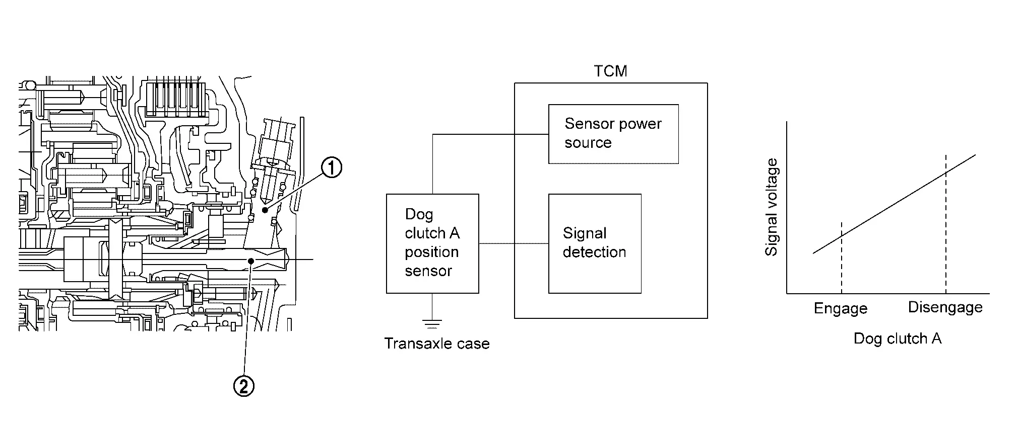
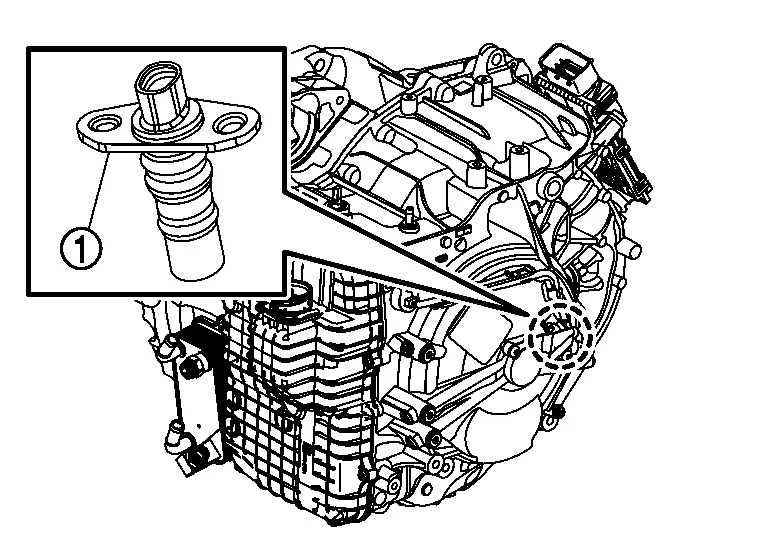
COMPONENT PARTS LOCATION
Dog clutch A position sensor  is installed side of the transaxle assembly.
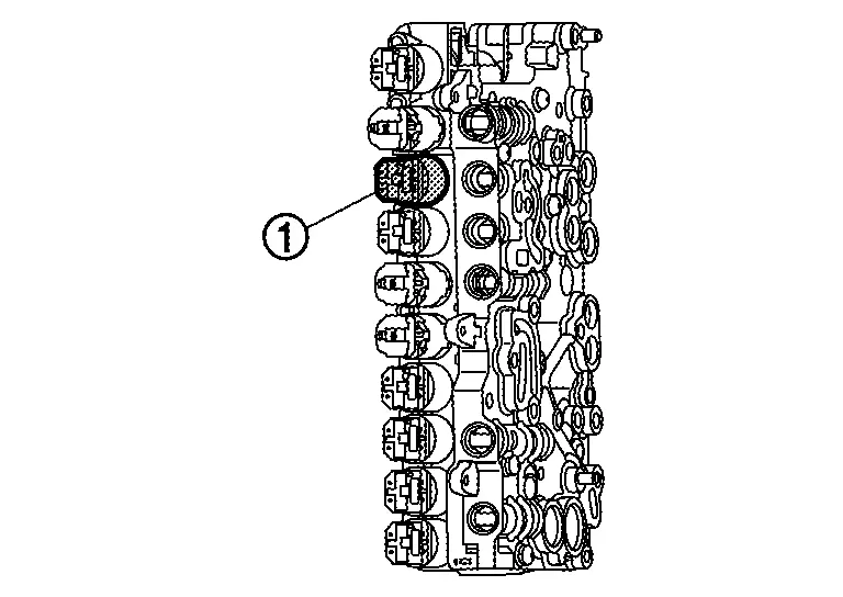
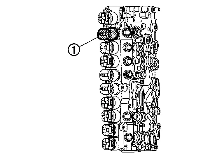
Dog Clutch F Position Sensor
FUNCTIONS WITHIN THE SYSTEM
Dog clutch F position sensor transfers current position – open or engaged – of the dog clutch F to TCM as PWM signal.
INDIVIDUAL FUNCTION WITHIN SYSTEM
Dog clutch F position sensor transfers current position – open or engaged – of the dog clutch F.
INDIVIDUAL OPERATION
To determine the position of the dog clutch, sensor  with magnetically biased (back-bias magnet) differential Hall cells are used. Depending on the position of the sensor relative to the axially displaceable dual cone
  , different air gaps result between the dual cone and the respective Hall cells. This results in different magnetic flux densities and these in turn cause different Hall voltages. The resulting voltage difference is then output as a PWM signal and is further processed by the transmission control unit.
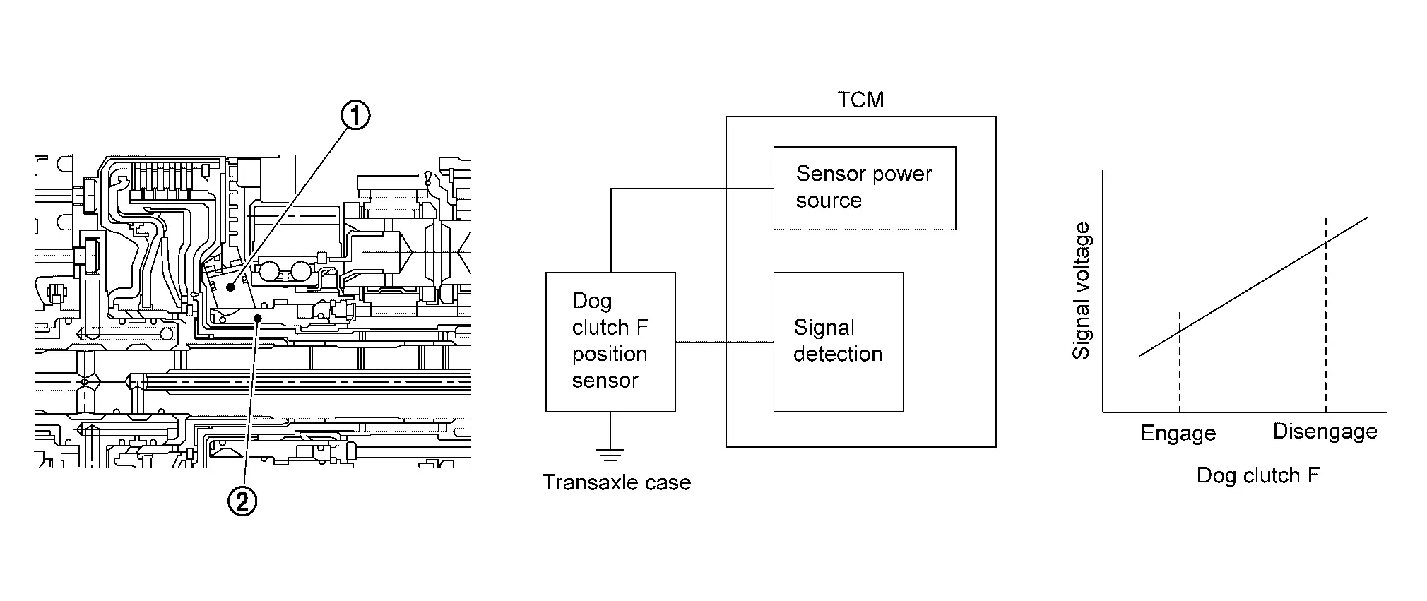
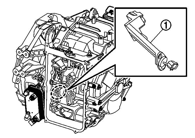
COMPONENT PARTS LOCATION
Dog clutch F position sensor  is built into the transaxle assembly.
Dog Clutch A Solenoid Valve
FUNCTIONS WITHIN THE SYSTEM
Dog clutch A solenoid valve controls the engaging oil pressure of dog clutch A according to the TCM signal.
INDIVIDUAL FUNCTION WITHIN SYSTEM
Dog clutch A solenoid valve controls the engaging oil pressure of dog clutch A.
INDIVIDUAL OPERATION
-
Dog clutch A solenoid valve utilizes an ON/OFF type solenoid valve.
-
When the dog clutch A solenoid valve is turned on, oil for dog clutch A engagement is supplied.
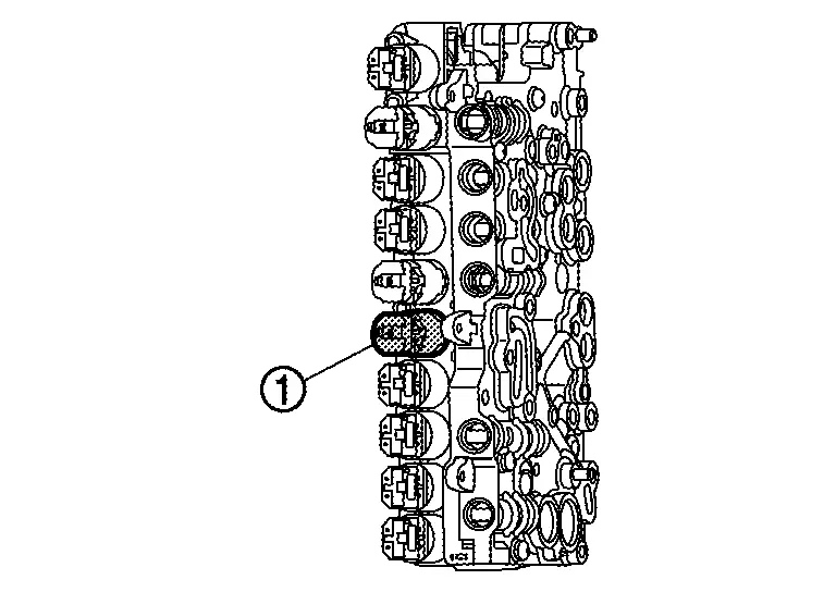
COMPONENT PARTS LOCATION
Dog clutch A solenoid valve  is assembled to the control valve assembly.
Dog Clutch F Solenoid Valve
FUNCTIONS WITHIN THE SYSTEM
Dog clutch F solenoid valve controls the engaging oil pressure of dog clutch F according to the TCM signal.
INDIVIDUAL FUNCTION WITHIN SYSTEM
Dog clutch F solenoid valve controls the engaging oil pressure of dog clutch F.
INDIVIDUAL OPERATION
-
Dog clutch A solenoid valve utilizes an ON/OFF type solenoid valve.
-
When the dog clutch F solenoid valve is turned on, oil for dog clutch F engagement is supplied.
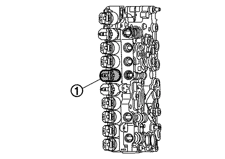
COMPONENT PARTS LOCATION
Dog clutch F solenoid valve  is assembled to the control valve assembly.
Clutch B Pressure Regulator
FUNCTIONS WITHIN THE SYSTEM
Clutch B pressure regulator valve controls the engaging oil pressure of clutch B according to the TCM signal.
INDIVIDUAL FUNCTION WITHIN SYSTEM
Clutch B pressure regulator controls the engaging oil pressure of clutch B.
INDIVIDUAL OPERATION
-
Clutch B pressure regulator utilizes a linear solenoid valve [N/L (normal low) type].
-
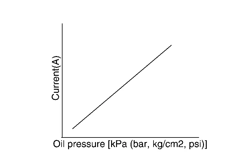
The principle of the linear solenoid valve utilizes the fact that the force pressing on the valve spool installed inside the coil increases nearly in proportion to the current. This allows it to produce a fluid pressure that is proportional to this pressing force.
-
The N/L (normal low) type does not produce hydraulic control when the coil is not energized.
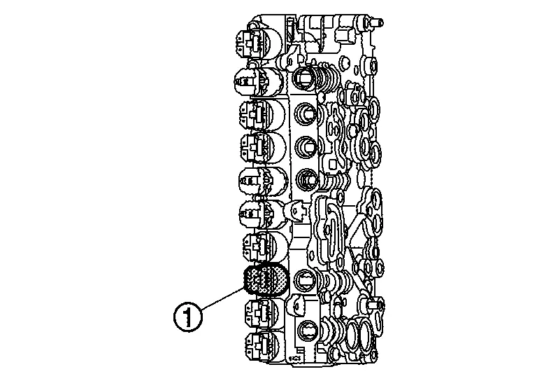
COMPONENT PARTS LOCATION
Clutch B pressure regulator  is assembled to the control valve assembly.
Clutch E Pressure Regulator
FUNCTIONS WITHIN THE SYSTEM
Clutch E pressure regulator controls the engaging oil pressure of clutch E according to the TCM signal.
INDIVIDUAL FUNCTION WITHIN SYSTEM
Clutch E pressure regulator controls the engaging oil pressure of clutch E.
INDIVIDUAL OPERATION
-
Clutch E pressure regulator utilizes a linear solenoid valve [N/L (normal low) type].
-
The principle of the linear solenoid valve utilizes the fact that the force pressing on the valve spool installed inside the coil increases nearly in proportion to the current. This allows it to produce a fluid pressure that is proportional to this pressing force.
-
The N/L (normal low) type does not produce hydraulic control when the coil is not energized.

COMPONENT PARTS LOCATION
Clutch E pressure regulator  is assembled to the control valve assembly.
Brake C Pressure Regulator
FUNCTIONS WITHIN THE SYSTEM
Brake C pressure regulator controls the engaging oil pressure of brake C according to the TCM signal.
INDIVIDUAL FUNCTION WITHIN SYSTEM
Brake C pressure regulator controls the engaging oil pressure of brake C.
INDIVIDUAL OPERATION
-
Brake C pressure regulator utilizes a linear solenoid valve [N/L (normal low) type].
-
The principle of the linear solenoid valve utilizes the fact that the force pressing on the valve spool installed inside the coil increases nearly in proportion to the current. This allows it to produce a fluid pressure that is proportional to this pressing force.
-
The N/L (normal low) type does not produce hydraulic control when the coil is not energized.

COMPONENT PARTS LOCATION
Brake C pressure regulator  is assembled to the control valve assembly.
Brake D Pressure Regulator
FUNCTIONS WITHIN THE SYSTEM
Brake D pressure regulator controls the engaging oil pressure of brake D according to the TCM signal.
INDIVIDUAL FUNCTION WITHIN SYSTEM
Brake D pressure regulator controls the engaging oil pressure of brake D.
INDIVIDUAL OPERATION
-
Brake D pressure regulator utilizes a linear solenoid valve [N/L (normal low) type].
-
The principle of the linear solenoid valve utilizes the fact that the force pressing on the valve spool installed inside the coil increases nearly in proportion to the current. This allows it to produce a fluid pressure that is proportional to this pressing force.
-
The N/L (normal low) type does not produce hydraulic control when the coil is not energized.

COMPONENT PARTS LOCATION
Brake D pressure regulator  is assembled to the control valve assembly.
Line Pressure Control Pressure Regulator
FUNCTIONS WITHIN THE SYSTEM
Line pressure control pressure regulator adjusts the pressure discharge amount of the oil pump according to the driving condition.
INDIVIDUAL FUNCTION WITHIN SYSTEM
Line pressure control pressure regulator adjusts the pressure discharge amount of the oil pump.
INDIVIDUAL OPERATION
-
Line pressure control pressure regulator utilizes a linear solenoid valve [N/H (normal high) type].
-
The principle of the linear solenoid valve utilizes the fact that the force pressing on the valve spool installed inside the coil increases nearly in proportion to the current. This allows it to produce a fluid pressure that is proportional to this pressing force.
-
The N/H (normal high) type does produce hydraulic control when the coil is not energized.
COMPONENT PARTS LOCATION
Line pressure control pressure regulator  is assembled to the control valve assembly.
Parking Lock Valve
FUNCTIONS WITHIN THE SYSTEM
Parking lock valve controls the system pressure applied to the face end of the parking lock cylinder to release a parking lock.
INDIVIDUAL FUNCTION WITHIN SYSTEM
Parking lock valve controls the system pressure applied to the face end of the parking lock cylinder.
INDIVIDUAL OPERATION
-
Parking lock valve utilizes an ON/OFF type solenoid valve.
-
When the parking lock valve is turned on, oil for parking lock release is supplied.
COMPONENT PARTS LOCATION
Parking lock valve  is assembled to the control valve assembly.
Parking Lock Actuator
FUNCTIONS WITHIN THE SYSTEM
Parking lock actuator holds the parking lock cylinder by a magnet when the parking lock is released.
INDIVIDUAL FUNCTION WITHIN SYSTEM
Parking lock actuator holds the parking lock cylinder by a magnet.
INDIVIDUAL OPERATION
Parking lock actuator (holding magnet), which is used to secure the parking lock cylinder when the parking lock is released, allows to keep the parking lock released for a defined period of time when in the neutral and engine off position (no hydraulic supply present). Following this period, the current at the holding magnet decreases, the locking mechanism is released and the parking lock engaged. The parking lock can only be released upon restart. Refer to System Description for the movement of the parking lock actuator.
COMPONENT PARTS LOCATION
Parking lock actuator  is assembled to the control valve assembly.
Torque Converter Clutch Pressure Regulator
FUNCTIONS WITHIN THE SYSTEM
Torque converter clutch pressure regulator controls the engaging oil pressure of torque converter lock-up clutch according to the TCM signal.
INDIVIDUAL FUNCTION WITHIN SYSTEM
Torque converter clutch pressure regulator controls the engaging oil pressure of torque converter lock-up clutch.
INDIVIDUAL OPERATION
-
Torque converter clutch pressure regulator utilizes a linear solenoid valve [N/L (normal low) type].
-
The principle of the linear solenoid valve utilizes the fact that the force pressing on the valve spool installed inside the coil increases nearly in proportion to the current. This allows it to produce a fluid pressure that is proportional to this pressing force.
-
The N/L (normal low) type does not produce hydraulic control when the coil is not energized.

COMPONENT PARTS LOCATION
Torque converter clutch pressure regulator  is assembled to the control valve assembly.
Electric Shift System Component Parts Location
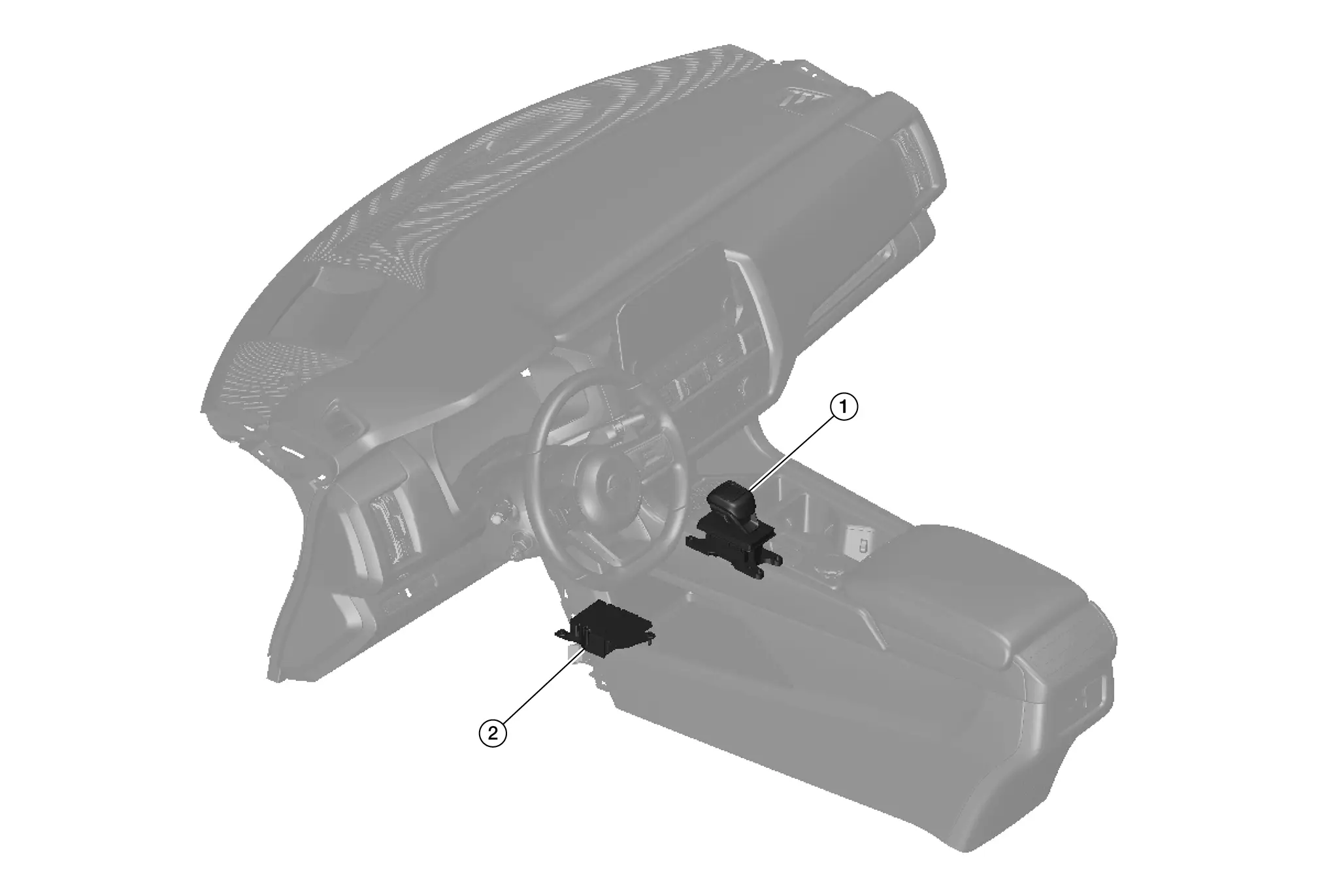
 |
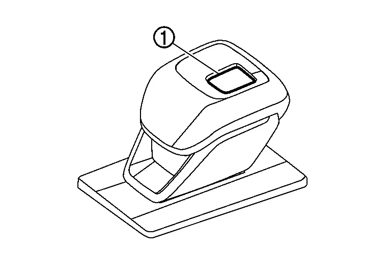
Electric shift selector |  |
Electric shift control module | ||
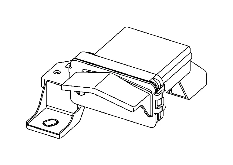
Electric Shift Control Module
FUNCTIONS WITHIN THE SYSTEM
Electric shift control module actuates the shift actuator according to the signals transmitted from electric shift sensor, P position switch and various ECUs.
INDIVIDUAL FUNCTION WITHIN SYSTEM
-
Electric shift control module consists of the microcomputer and input/output connectors for signal and power supply.
-
Electric shift control module includes a self-diagnosis function for simplifying trouble diagnosis.
INDIVIDUAL OPERATION
Electric shift control module controls electric shift system.
COMPONENT PARTS LOCATION
Electric shift control module is installed below the center console.
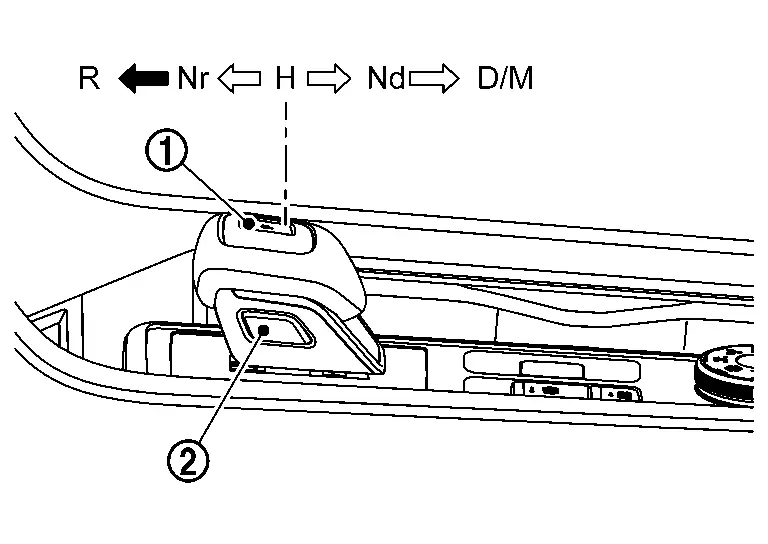
Electric Shift Selector
FUNCTIONS WITHIN THE SYSTEM
Electric shift selector sends the shift request of the driver to the electric shift control module as an electric signal.
INDIVIDUAL FUNCTION WITHIN SYSTEM
| Shift selector position | Operation/Function | |
|---|---|---|
|
H (Home position) |
The selector lever automatically moves back to the home position after it is operated. |
 : Shift without pressing the button : Shift without pressing the button  |
|
P (P position switch ) ) |
Completely stop the Nissan Pathfinder vehicle and press the P position switch while depressing the brake pedal. The shift position changes to P. | |
| R | While depressing the brake pedal, press the selector knob button and shift the selector lever to R position. The shift position changes to R. | |
| Nr |
When shift position is D or M, while depressing the brake pedal, shift the selector lever to the Nr position and hold it for approx. 0.5 second. The shift position changes to N. Even if selector lever is shifted to the Nr position when shift position is R, the shift position does not change to N and the shift position warning buzzer sounds.
|
|
| Nd |
When shift position is R, while depressing the brake pedal, shift the selector lever to the Nd position and hold it for approx. 0.5 second. The shift position changes to N. Even if selector lever is shifted to the Nd position when shift position is D or M, the shift position does not change to N and the shift position warning buzzer sounds.
|
|
| D/M |
|
|
 : Press the button
  to shift
 NOTE:
NOTE:  NOTE:
NOTE:  : Hold
  : Current shift position
  : Be able to shift here
| POWER SW | Current shift position | Requested range by driver | Speed condition | Brake condition | Shift position | Refuse buzzer | ||||
|---|---|---|---|---|---|---|---|---|---|---|
| P | R | N | D | M | ||||||
| OFF/ACC | P | R, N, D, M | — | — |  |
|||||
| R, D, M | — | More than 2 km/h | — |  |
 |
 |
 |
|||
| ON (Engine stop) | P | R, N, D | — | — |  |
Beeping | ||||
| N | P position SW ON | Less than 2 km/h | — |  |
 |
|||||
| N | P position SW ON | More than 2 km/h | — |  |
Beeping | |||||
| N | R, D | — | — |  |
Beeping | |||||
| ON (Engine running) | P | R | — | ON |  |
 |
||||
| — | OFF |  |
Beeping | |||||||
| N | Less than 2 km/h | OFF |  |
Beeping | ||||||
| Less than 2 km/h | ON |  |
 |
|||||||
| More than or equal to 2 km/h | — |  |
 |
|||||||
| More than 8 km/h | — |  |
Beeping | |||||||
| D | Less than 8 km/h | — |  |
 |
||||||
| More than or equal to 8 km/h | — |  |
 |
Beeping | ||||||
| M | Less than 8 km/h | — |  |
 |
||||||
| More than or equal to 8 km/h | — |  |
 |
Beeping | ||||||
| ON (Engine running) | P | N | — | ON |  |
 |
||||
| — | OFF |  |
Beeping | |||||||
| R | — | — |  |
 |
||||||
| D | — | — |  |
 |
||||||
| M | — | — |  |
 |
||||||
| ON (Engine running) | P | D | — | ON |  |
 |
||||
| — | OFF |  |
Beeping | |||||||
| R | Less than 8 km/h | — |  |
 |
||||||
| More than or equal to 8 km/h | — |  |
 |
Beeping | ||||||
| N | Less than 2 km/h | OFF |  |
Beeping | ||||||
| Less than 2 km/h | ON |  |
 |
|||||||
| More than or equal to 2 km/h | — |  |
 |
|||||||
| More than 8 km/h | — |  |
Beeping | |||||||
| M | — | — |  |
 |
||||||
| ON (Engine running) | R, N, D, M | P position SW ON | Less than 2 km/h | — |  |
 |
 |
 |
 |
|
| More than or equal to 2 km/h | — |  |
 |
 |
 |
Beeping | ||||
| P | R, N, D | — | — |  |
Beeping | |||||
INDIVIDUAL OPERATION
Electric shift selector sends a signal to the electric shift control module by shifting.
COMPONENT PARTS LOCATION
Electric shift selector is installed on the center console.
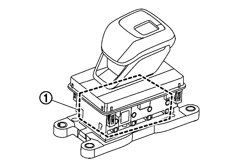
Electric Shift Sensor
FUNCTIONS WITHIN THE SYSTEM
Electric shift control module determines the shift selector position from the combination of the electric shift sensor ON/OFF signals.
INDIVIDUAL FUNCTION WITHIN SYSTEM
Electric shift sensor has 8 non-contact sensors (Hall IC) built in. Each sensor switches ON/OFF according to the selector lever position.
| Selector lever position | Electric shift sensor | |||||||
|---|---|---|---|---|---|---|---|---|
| No. 1 | No. 2 | No. 3 | No. 4 | No. 5 | No. 6 | No. 7 | No. 8 | |
| R | ON | ON | OFF | OFF | OFF | OFF | OFF | OFF |
| Nr | ON | ON | ON | ON | ON | OFF | OFF | OFF |
| H | ON | ON | ON | ON | ON | ON | ON | ON |
| Nd | OFF | OFF | OFF | ON | ON | ON | ON | ON |
| D/M | OFF | OFF | OFF | OFF | OFF | OFF | ON | ON |
INDIVIDUAL OPERATION
Electric shift sensor transmits ON/OFF signals according to the selector lever position to the electric shift control module.
COMPONENT PARTS LOCATION
Electric shift sensor  is built into the electric shift selector.
P Position Switch
FUNCTIONS WITHIN THE SYSTEM
The transaxle changes to P position by pressing the P position switch.
INDIVIDUAL FUNCTION WITHIN SYSTEM
P position switch transmits the ON/OFF signals of 2 contact switches to the electric shift control module.
| P position switch | P position switch | |
|---|---|---|
| No. 1 | No. 2 | |
| Press | ON | OFF |
| No press | OFF | ON |
INDIVIDUAL OPERATION
P position switch allows direct one-touch switching to the P position from any position while the Nissan Pathfinder vehicle is stopped.
COMPONENT PARTS LOCATION
P position switch  is built into the electric shift selector knob.
Electric Shift Warning Lamp
DESIGN/PURPOSE
The electric shift warning lamp illuminates when a malfunction occursin the electric shift control system.

BULB CHECK
For 2 seconds after the ignition switch is turned ON.
SYNCHRONIZATION WITH MASTER WARNING
Not applicable
OPERATION AT COMBINATION METER CAN COMMUNICATION CUT-OFF OR UNUSUAL SIGNAL
For actions on CAN communications blackout in the combination meter, refer to Fail-Safe.
SYSTEM DIAGRAM
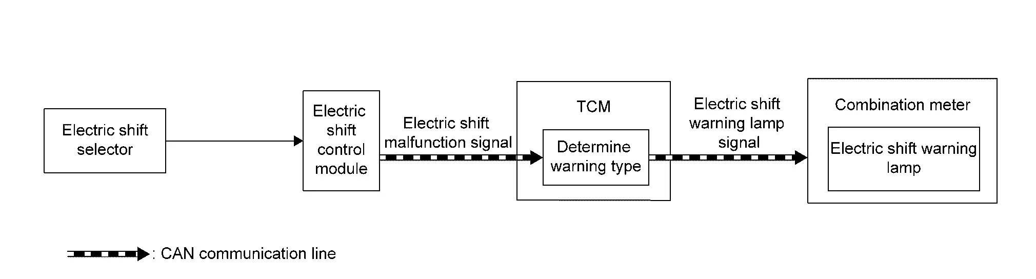
SIGNAL PATH
-
The electric shift control module transmits an electric shift malfunction signal to the TCM when detecting malfunction in the electric shift system.
-
The TCM transmits an electric shift warning lamp signal to the combination meter according to electric shift malfunction signal.
-
The combination meter turns ON the electric shift warning lamp according to signal.
LIGHTING CONDITION
When any of the following conditions are satisfied.
-
Shift position is except P position
-
Electric shift system malfunction (Transmission does not shift to P position due to electric shift system malfunction)
-
Nissan Pathfinder Vehicle speed is less than 7 km/h (4 MPH)
SHUTOFF CONDITION
When any of the conditions listed below is satisfied:
-
Shift position is P position
-
Electric shift system is normal
-
Nissan Pathfinder Vehicle speed is 7 km/h (4 MPH) or more

Nissan Pathfinder (R53) 2022-2026 Service Manual
Contact Us
Nissan Pathfinder Info Center
Email: info@nipathfinder.com
Phone: +1 (800) 123-4567
Address: 123 Pathfinder Blvd, Nashville, TN 37214, USA
Working Hours: Mon–Fri, 9:00 AM – 5:00 PM (EST)
