Nissan Pathfinder: Driver Assistance System - Chassis Control
- Precautions
- Ecu Diagnosis Information. Chassis Control Module
- Symptom Diagnosis. Chassis Control System
- Removal and Installation. Chassis Control Module
Precautions Nissan Pathfinder SUV
Precaution for Supplemental Restraint System (SRS) "AIR BAG" and "SEAT BELT PRE-TENSIONER"
The Supplemental Restraint System such as “AIR BAG” and “SEAT BELT PRE-TENSIONER”, used along with a front seat belt, helps to reduce the risk or severity of injury to the driver and front passenger for certain types of collisions.
Information necessary to service the system safely is included in the “SRS AIR BAG” and “SEAT BELT” sections of this Service Manual.
WARNING:
Always observe the following items for preventing accidental activation:
-
To avoid rendering the SRS inoperative, which could increase the risk of personal injury or death in the event of a collision that would result in air bag inflation, it is recommended that all maintenance and repair be performed by an authorized NISSAN/INFINITI dealer.
-
Improper repair, including incorrect removal and installation of the SRS, can lead to personal injury caused by unintentional activation of the system. For removal of Spiral Cable and Air Bag Module, see “SRS AIR BAG”.
-
Never use electrical test equipment on any circuit related to the SRS unless instructed to in this Service Manual. SRS wiring harnesses can be identified by yellow and/or orange harnesses or harness connectors.
PRECAUTIONS WHEN USING POWER TOOLS (AIR OR ELECTRIC) AND HAMMERS
WARNING:
Always observe the following items for preventing accidental activation:
-
When working near the Air Bag Diagnosis Sensor Unit or other Air Bag System sensors with the ignition/power switch ON or engine running, never use air or electric power tools or strike near the sensor(s) with a hammer. Heavy vibration could activate the sensor(s) and deploy the air bag(s), possibly causing serious injury.
-
When using air or electric power tools or hammers, always place the ignition/power switch in the OFF position, disconnect the 12V battery or batteries, and wait at least 3 minutes before performing any service.
Precautions for Harness Repair
-
Solder the repaired area and wrap tape around the soldered area.
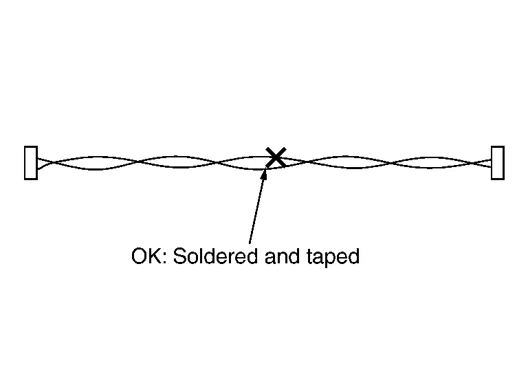
 NOTE:
NOTE:
A fray of twisted lines must be within 110 mm (4.33 in).
-
Bypass connection is never allowed at the repaired area.
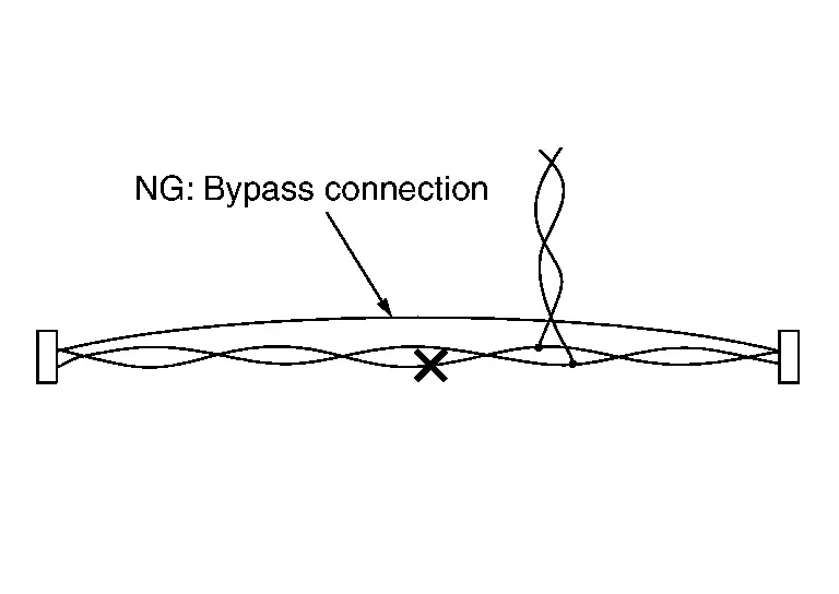
 NOTE:
NOTE:
Bypass connection may cause CAN communication error. The spliced wire becomes separated and the characteristics of twisted line are lost.
-
Replace the applicable harness as an assembly if error is detected on the shield lines of CAN communication line.
Precaution for Chassis Control
-
Never disassemble the chassis control module.
-
The parts must not be reused if they are dropped.
-
Never perform "Active Test" while driving the Nissan Pathfinder vehicle.
-
When the intelligent trace control function and active ride control function (if equipped) are activated, the driver may feel some vibration on the brake pedal, hear operating sound, or have feel of the deceleration. This is not a malfunction because it is caused by intelligent trace control function and active ride control function (if equipped) that is normally operated.
-
When the intelligent trace control function is activated, engine sound becomes loud or the tachometer needle fluctuates. This is not a malfunction because it is caused by intelligent trace control function that is normally operated.
-
Intelligent trace control function and active ride control function (if equipped) are not always activated in any driving conditions.
Ecu Diagnosis Information. Chassis Control Module Nissan Pathfinder R53
Reference Value
 NOTE:
NOTE:
The following table includes information (items) inapplicable to this Nissan Pathfinder vehicle. For information (items) applicable to this vehicle, refer to CONSULT display items.
| Monitor item | Condition | Reference values in normal operation |
|---|---|---|
| Battery voltage | Always | 6 - 16 V |
| ACC voltage | Ignition switch ACC | 6 - 16 V |
| CONTROL MODULE MALF | When chassis control module is normal | Off |
| When chassis control module is malfunction | On | |
| Diag permission condition | When not communication | Not permission |
| During communication | Permission | |
| When communication is malfunction*1 | Abnormal | |
| Chassis control malfunction display | When chassis control warning is dysplayed | On |
| When chassis control warning is not displayed | Off | |
| Nissan Pathfinder Vehicle Wheel Speed | Vehicle stopped | 0 km/h |
| Nissan Pathfinder Vehicle driving*2 | Almost same reading as speedometer (Within ±10%) | |
| Nissan Pathfinder Vehicle body speed | Vehicle stopped | 0 km/h |
| Nissan Pathfinder Vehicle driving*2 | Almost same reading as speedometer (Within ±10%) | |
| FR WHEEL SPEED | Nissan Pathfinder Vehicle stopped | 0 rpm |
| Vehicle driving*2 | Increases according to Nissan Pathfinder vehicle speed | |
| FL WHEEL SPEED | Nissan Pathfinder Vehicle stopped | 0 rpm |
| Nissan Pathfinder Vehicle driving*2 | Increases according to vehicle speed | |
| RR WHEEL SPEED | Nissan Pathfinder Vehicle stopped | 0 rpm |
| Nissan Pathfinder Vehicle driving*2 | Increases according to vehicle speed | |
| RL WHEEL SPEED | Nissan Pathfinder Vehicle stopped | 0 rpm |
| Nissan Pathfinder Vehicle driving*2 | Increases according to vehicle speed | |
| STEERING ANG SENSOR | When Nissan Pathfinder vehicle driving straight | 0±3.5 deg |
| When steering wheel is steered to RH by 90° | Approx. +90 deg | |
| When steering wheel is steered to LH by 90° | Approx. −90 deg | |
| DECEL G SENSOR | Nissan Pathfinder Vehicle stopped | Approx. 0 G |
| When during acceleration | Positive value | |
| When during deceleration | Negative value | |
| Decel G | Nissan Pathfinder Vehicle stopped | Approx. 0 G |
| When during acceleration | Positive value | |
| When during deceleration | Negative value | |
| SIDE G SENSOR | Nissan Pathfinder Vehicle stopped | Approx. 0 G |
| When right turn | Negative value | |
| When left turn | Positive value | |
| YAW RATE SENSOR | Nissan Pathfinder Vehicle stopped | Approx. 0 deg/s |
| When right turn | Negative value | |
| When left turn | Positive value | |
| ACCELE PEDAL POSITION | When accelerator pedal is released | 0% |
| When accelerator pedal is depressed | 0 − 100% | |
| PRESS SENSOR | When brake pedal is not depressed | Approx. 0 bar |
| When brake pedal is depressed | 0 − 126 bar | |
| Throttle control | When electric throttle control actuator is normal | Normal |
| When the engine torque command cannot be executed correctly | Abnormal 1 | |
| When the engine torque command cannot be executed (transient state) | Abnormal 2 | |
| When the engine torque command cannot be executed | Abnormal 3 | |
| SHIFT POSITION | Selector lever in any position | Indicates selected electric shift selector position |
| STOP LAMP SW | When brake pedal is not depressed | Brake pedal not operation |
| When brake pedal is depressed | Brake pedal operation 1 | |
| When brake pedal being depressed is confirmed | Brake pedal operation 2 | |
| When stop lamp switch is malfunction*1 | Abnormal | |
| ABS | When ABS function is inactive | INACT |
| When ABS function is active | ACTIVE | |
| ABS MALF | When ABS function is malfunction | On |
| When ABS function is not malfunction | Off | |
| EBD | When EBD function is inactive | INACT |
| When EBD function is active | ACTIVE | |
| TCS | When TCS function is malfunction | INACT |
| When TCS function is normal | ACTIVE | |
| TCS MALF | When TCS function is malfunction | On |
| When TCS function is not malfunction | Off | |
| VDC | When VDC function is inactive | INACT |
| When VDC function is active | ACTIVE | |
| VDC MALF | When VDC function is malfunction | On |
| When VDC function is not malfunction | Off | |
| VDC OFF SWITCH | When VDC OFF function is ON | On |
| When VDC OFF function is OFF | Off | |
| ICC brake active status | When brake function of ADAS system is permitted | PERMIT |
| When brake function of ADAS system is not permitted | NO PER | |
| When ADAS system is malfunction*1 | Abnormal | |
| Yaw rate (ADAS) | When yaw rate (braking) control by ADAS system | Braking |
| When yaw rate (braking) not control by ADAS system | No braking | |
| When ADAS system is malfunction*1 | Abnormal | |
| ProPILOT park | — | Displays but not used |
| Brake torque request | When active ride control is active | Change according to input of brake control |
| When active ride control is inactive | 0 Nm | |
| Command BR torque (CCS) | — | Displays but not used |
| Command BR torque (HPCM) | — | Displays but not used |
| Command BR torque (ADAS) 1 | When no brake torque command from ADAS control unit 2 | 0 Nm |
| When brake torque command from ADAS control unit 2 | Change according to brake command from ADAS control unit 2 | |
| Command BR torque (ADAS) 2 | When no brake torque command from ADAS control unit 2 | 0 Nm |
| When brake torque command from ADAS control unit 2 | Change according to brake command from ADAS control unit 2 | |
| Reg brake request (HPCM) | — | Displays but not used |
| Driver brake torque request | — | Displays but not used |
| CC/SL active status 1 | — | Displays but not used |
| Yaw control status | — | Displays but not used |
| Control status (VDC) 1 | When VDC function is impossible | Impossi |
| When VDC function is possible | Possible | |
| Control status (VDC) 2 | When VDC function is impossible | Impossi |
| When VDC function is possible | Possible | |
| Maintenance mode status | When not used | NOT |
| When Not requested | No req | |
| When requested | request | |
| When unavailable | Unavail | |
| Reg brake status (VDC) | — | Displays but not used |
| Engine control status 1 | — | Displays but not used |
| Engine control status 2 | — | Displays but not used |
| CC/SL active status 2 | — | Displays but not used |
| Brake active request (ADAS) 1 | When VDC function is impossible | Impossi |
| When VDC function is possible | Possible | |
| Brake active request (ADAS) 2 | When not requested | Inactive |
| When requested of other parking system | 1 | |
| When requested of parking system | 2 | |
| Brake active request (ADAS) 3 | When not requested | NO REQ |
| When requested | REQ | |
| Rear wheel steering status 1 | — | Displays but not used |
| Rear wheel steering status 2 | — | Displays but not used |
| ATC/ITC status 2 | When normal status | Normal |
| When malfunction status | Malf | |
| ATC/ITC status 3 | When normal status | Normal |
| When malfunction status | Malf | |
| ATC/ITC status 4 | When normal status | Normal |
| When malfunction status | Malf | |
| ATC/ITC status 5 | When normal status | Normal |
| When malfunction status | Malf | |
| ITC/ATC status (ENG control) 1 | — | Displays but not used |
| ITC/ATC status (ENG control) 2 | — | Displays but not used |
| ITC/ATC status (BR control)1 | — | Displays but not used |
| ITC/ATC status (BR control)2 | — | Displays but not used |
| IEB/AEB status 1 | — | Displays but not used |
| IEB/AEB status 2 | — | Displays but not used |
| ARC/IRC status 1 | When normal status | Normal |
| When malfunction status | Malf | |
| ARC/IRC status 2 | When normal status | Normal |
| When malfunction status | Malf | |
| Chassis control (ADAS) 1 | When normal status | Normal |
| When malfunction status | Malf | |
| Chassis control (ADAS) 2 | When normal status | Normal |
| When malfunction status | Malf | |
| ARC/IRC status 3 | When normal status | Normal |
| When malfunction status | Malf | |
| ARC/IRC status 4 | When normal status | Normal |
| When malfunction status | Malf | |
| Parking brake operation status | When electric parking brake system is release | Release |
| When electric parking brake system is apply | Apply | |
| When electric parking brake function is malfunction*1 | Abnormal | |
| Stop hold (VDC) | When stop hold status is release | Release |
| When stop hold status is active | Hold | |
| When stop hold status is impossible | Impossible | |
| FR wheel speed pulse (stop hold) | Nissan Pathfinder Vehicle stopped | 0 |
| Vehicle driving*2 | Increases according to Nissan Pathfinder vehicle speed | |
| FL wheel speed pulse (stop hold) | Nissan Pathfinder Vehicle stopped | 0 |
| Vehicle driving*2 | Increases according to Nissan Pathfinder vehicle speed | |
| RR wheel speed pulse (stop hold) | Nissan Pathfinder Vehicle stopped | 0 |
| Vehicle driving*2 | Increases according to Nissan Pathfinder vehicle speed | |
| RL wheel speed pulse (stop hold) | Nissan Pathfinder Vehicle stopped | 0 |
| Vehicle driving*2 | Increases according to Nissan Pathfinder vehicle speed | |
| ICC status | When ADAS system is OFF | Off |
| When ADAS system is operation | Operation | |
| When ADAS system is stop | Stop | |
| When ADAS system is wait | Wait | |
| When ADAS system is suspended | Suspend | |
| When ADAS system is brake mode | Brake mode | |
| When ADAS system is regulation | Regulation | |
| When ADAS system is driver override | Driver override | |
| When ADAS system is malfunction | Malfunction | |
| ABH warning display request | When automatic brake hold warning is not displayed | No request |
| When automatic brake hold warning is displayed | Request | |
| ABH select status | When automatic brake hold function is OFF mode | OFF mode |
| When automatic brake hold function is auto mode | AUTO mode | |
| ABH status 1 | When automatic brake hold function is inactive | Inactive |
| When automatic brake hold function is active | Active | |
| ABH status 2 | When automatic brake hold function is inactive | Inactive |
| When automatic brake hold function is active | Active | |
| EPB active request (ABH) | When active request of electric parking brake system is not requested (automatic brake hold function) | No request |
| When active of electric parking brake system is requested (automatic brake hold function) | Request | |
| ABH stop hold request 2 | When stop hold of automatic brake hold function is not requested | NO REQ |
| When stop hold of automatic brake hold function is requested | REQ | |
| ABH status 3 | —*3 | Displays but not used*3 |
| When automatic brake hold function is inactive*4 | No request*4 | |
| When automatic brake hold function is active*4 | Request*4 | |
| ProPILOT stop hold status | —*3 | Displays but not used*3 |
| When stop hold not request from Pro PILOT (Current)*4 | No request*4 | |
| When stop hold request from Pro PILOT (Current)*4 | Active*4 | |
| EPB active request (ProPILOT) | —*3 | Displays but not used*3 |
| When inactive request of electric parking brake system (ProPILOT)*4 | Inactive*4 | |
| When active request of electric parking brake system (ProPILOT)*4 | Request*4 | |
| ABH active request (ProPILOT) | —*3 | Displays but not used*3 |
| When inactive request of automatic brake hold function (ProPILOT)*4 | No request*4 | |
| When active request of automatic brake hold function (ProPILOT)*4 | Request*4 | |
| ABH SW 2 | When automatic brake hold switch is not push | No push |
| When automatic brake hold switch is pushing | Push | |
| ABH SW indicator lamp 3 | When lighting request of automatic brake hold switch indicator | On |
| When not lighting request of automatic brake hold switch indicator | Off | |
| DRIVE MODE SELECTOR | Always | (Mode 0 - 30) |
| User | — | Displays but not used |
| Drive Mode Selector | —*5 | Displays but not used*5 |
| Always*6 | (Mode 0 - 255)*6 | |
| Engine/TM setting | — | Displays but not used |
| STRG SETTING | — | Displays but not used |
| 4WD setting | — | Displays but not used |
| ATC SETTING | — | Displays but not used |
| ICC setting | — | Displays but not used |
| I-KEY LINK | — | Displays but not used |
| LOG-IN PERMIS | — | Displays but not used |
| Drive mode select switch (UP) | When drive mode select switch is not operation*5 | Not operation*5 |
| When drive mode select switch is operation (Up)*5 | Operation*5 | |
| —*6 | Displays but not used*6 | |
| Drive mode select switch (DOWN) | When drive mode select switch is not operation*5 | Displays but not used*5 |
| When drive mode select switch is operation (Down)*5 | Not operation*5 | |
| —*6 | Displays but not used*6 |
*1: It may be displayed when initializing communication.
*2: Check tire pressure under normal conditions.
*3: Without ProPILOT models
*4: With ProPILOT models
*5: 2WD models
*6: 4WD models
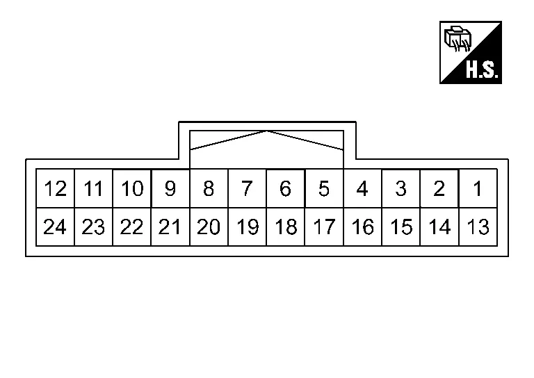
TERMINAL LAYOUT
PHYSICAL VALUES
|
Terminal No. (Wire color) | Description | Condition | Value | |||
|---|---|---|---|---|---|---|
| + | − | Signal name | Input/Output | |||
|
3 (GR) |
Ground | CAN-H | — | — | — | — |
|
4 (R) |
CAN-L | — | — | — | — | |
|
5 (LA/G) |
Accessory power supply | Input | Ignition switch ON | 6 - 16 V | ||
|
7 (V) |
CAN-L | — | — | — | — | |
|
8 (GR) |
CAN-H | — | — | — | — | |
|
9 (GR) |
CAN-H | — | — | — | — | |
|
13 (R) |
Battery power supply | — | Always | 6 - 16 V | ||
|
15 (B) |
Ground | — | Ignition switch ON | — | Approx. 0 V | |
|
16 (G) |
CAN-L | — | — | — | — | |
|
17 (GR) |
CAN-H | — | — | — | — | |
|
19 (GR) |
CAN-H | — | — | — | — | |
|
20 (G) |
CAN-L | — | — | — | — | |
|
21 (V) |
CAN-L | — | — | — | — | |
|
22 (V) |
Automatic brake hold switch indicator | Output | Ignition switch ON | Automatic brake hold function ON | Approx. 4 V | |
| Automatic brake hold function OFF | Approx. 12 V | |||||
|
24 (SB) |
Automatic brake hold switch | Input | Ignition switch ON | Automatic brake hold switch is pushing | Approx. 0 V | |
Fail-safe
Refer to Fail-safe.
DTC Inspection Priority Chart
When multiple DTCs are displayed simultaneously, check them one by one according to the following priority list.
| Priority | Detected item (DTC) |
|---|---|
| 1 |
|
| 2 |
|
| 3 |
|
| 4 |
|
| 5 |
|
| 6 |
|
DTC Index
Self Diagnostic Result
| DTC | Display item | Warning massage | Refer to |
|---|---|---|---|
| C1B80-54 | Calibration not completed | ON | DTC Description |
| C1B81-55 | Configuration not completed | ON | DTC Description |
| C1B8F-82 | IPDM E/R COMM | ON | DTC Description |
| C1B92-82 | BRAKE CONTROL SYSTEM | ON | DTC Description |
| C1B93-82 | ENGINE/HEV SYSTEM | ON | DTC Description |
| C1B94-82 | TM SYSTEM | ON | DTC Description |
| C1B96-82 | ADAS SYSTEM | - | DTC Description |
| C1B97-82 | BCM | ON | DTC Description |
| C1BB4-44 | CONTROL MODULE | ON | DTC Description |
| C1BB4-45 | CONTROL MODULE | ON* | DTC Description |
| C1BB4-46 | CONTROL MODULE | ON | DTC Description |
| C1BB4-49 | CONTROL MODULE | ON* | DTC Description |
| U2140-83 | CAN comm err (ECM) | ON | DTC Description |
| U214F-83 | CAN comm err (BCM) | ON | DTC Description |
| U2152-83 | CAN comm err (ADAS control unit) | - | DTC Description |
| U215B-83 | CAN comm err (IPDM E/R) | ON | DTC Description |
| U2248-83 | CAN comm err (brake control unit) | ON | DTC Description |
| U2541-83 | CAN comm err (TCM) | ON | DTC Description |
*: Chassis control warning in information display turns ON/OFF according to a condition when DTC is detected.
Network-DTC
| DTC | Display item | Warning massage | Refer to |
|---|---|---|---|
| U0076-00 | Control module comm Bus D Off | - | DTC Description |
| U007A-00 | Control module comm Bus H Off | - | DTC Description |
| U2140-87 | CAN comm err (ECM) | ON | DTC Description |
| U214F-87 | CAN comm err (BCM) | ON* | DTC Description |
| U2152-87 | CAN comm err (ADAS control unit) | - | DTC Description |
| U215B-87 | CAN comm err (IPDM E/R) | ON | DTC Description |
| U2248-87 | CAN comm err (brake control unit) | ON | DTC Description |
| U2448-87 | CAN comm err (ABS control unit) | ON | DTC Description |
| U2541-87 | CAN comm err (TCM) | ON | DTC Description |
| U2A03-88 | CAN comm error | - | DTC Description |
| U2A0B-88 | CAN comm error | - | DTC Description |
| U2A0E-88 | CAN comm error | - | DTC Description |
*: Chassis control warning in information display turns ON/OFF according to a condition when DTC is detected.
MAC Diagnosis
| DTC | Display item | Warning massage | Refer to |
|---|---|---|---|
| U1327-52 | MAC key update | - | DTC Description |
| U1327-54 | MAC key update | - | DTC Description |
| U2140-57 | CAN comm err (ECM) | - | DTC Description |
| U214F-57 | CAN comm err (BCM) | - | DTC Description |
| U2152-57 | CAN comm err (ADAS control unit) | - | DTC Description |
| U2165-57 | CAN comm err (sonar) | - | DTC Description |
Symptom Diagnosis. Chassis Control System Nissan Pathfinder SUV
Symptom Table
INTELLIGENT TRACE CONTROL
Perform self-diagnosis using CONSULT before the symptom diagnosis. Perform trouble diagnosis if any DTC is detected. Refer to DTC Index.
| Symptom | Possible cause | Inspection item | |
|---|---|---|---|
| Intelligent trace control inoperative/ineffective | No intelligent trace control assist | VDC OFF setting is engaged. | VDC OFF setting to the OFF. |
| Brake pad wear. | Check the brake pads and replace if necessary. | ||
| Certain roads, inclement weather or driving conditions. | System is functioning normally, confirm the driving condition with the customer. | ||
| Excessive lag on turns | Wheel alignment. | Repair alignment malfunction. | |
| Road wheel tire condition is abnormal. | Check the road wheel tire. | ||
| Road wheel tire size is abnormal. | |||
| Certain roads, inclement weather or driving conditions. | System is functioning normally, confirm the driving condition with the customer. | ||
ACTIVE RIDE CONTROL (IF EQUIPPED)
| Symptom | Possible cause | Inspection item | |
|---|---|---|---|
| Active ride control inoperative/ineffective | No active ride control assist | VDC OFF setting is engaged. | VDC OFF setting to the OFF. |
| Brake pad wear. | Check the brake pads and replace if necessary. | ||
| Bumpy ride on bumpy road. | Road wheel tire condition is abnormal. | ||
| Bumpy ride on bumpy road | Road wheel tire condition is abnormal. | Check the road wheel tire. | |
| Road wheel tire size is abnormal. | |||
| Certain roads, inclement weather or driving conditions. | System is functioning normally, confirm the driving condition with the customer. | ||
Removal and Installation. Chassis Control Module Nissan Pathfinder R53
Removal and Installation
REMOVAL
CAUTION:
If replacing chassis control module, Perform "ADDITIONAL SERVICE WHEN REPLACING CHASSIS CONTROL MODULE." Refer to Description.
Remove the instrument panel assembly. Refer to Removal and Installation.
Release clip (A).
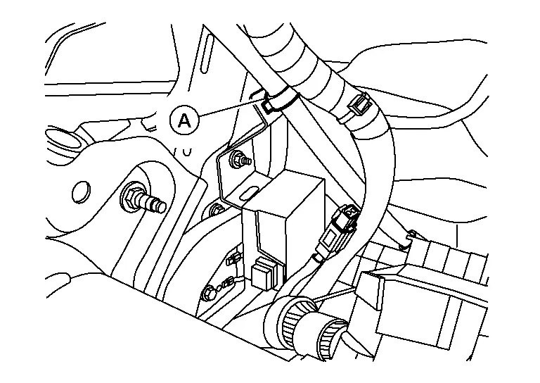
Disconnect the harness connector from chassis control module.
Remove nut (A), then remove chassis control module (1).
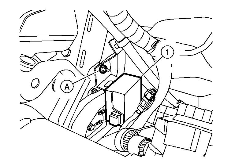
CAUTION:
Do not drop the chassis control module.
INSTALLATION
Installation is in the reverse order of removal.
CAUTION:
If replacing chassis control module, perform "ADDITIONAL SERVICE WHEN REPLACING CHASSIS CONTROL MODULE." Refer to Description.

Nissan Pathfinder (R53) 2022-2026 Service Manual
Chassis Control
- Precautions
- Ecu Diagnosis Information. Chassis Control Module
- Symptom Diagnosis. Chassis Control System
- Removal and Installation. Chassis Control Module
Contact Us
Nissan Pathfinder Info Center
Email: info@nipathfinder.com
Phone: +1 (800) 123-4567
Address: 123 Pathfinder Blvd, Nashville, TN 37214, USA
Working Hours: Mon–Fri, 9:00 AM – 5:00 PM (EST)
