Nissan Pathfinder: Lan System - Can Gateway
- Precautions
- Ecu Diagnosis Information. Can Gateway
- Basic Inspection. Additional Service When Replacing Can Gateway
- Removal and Installation. 8ch Can Gateway
Precautions Nissan Pathfinder Fifth generation
PRECAUTIONS FOR SUPPLEMENTAL RESTRAINT SYSTEM (SRS) AIR BAG AND SEAT BELT PRE-TENSIONER : Precautions
The Supplemental Restraint System such as “AIR BAG” and “SEAT BELT PRE-TENSIONER”, used along with a front seat belt, helps to reduce the risk or severity of injury to the driver and front passenger for certain types of collisions.
Information necessary to service the system safely is included in the “SRS AIR BAG” and “SEAT BELT” sections of this Service Manual.
WARNING:
Always observe the following items for preventing accidental activation:
-
To avoid rendering the SRS inoperative, which could increase the risk of personal injury or death in the event of a collision that would result in air bag inflation, it is recommended that all maintenance and repair be performed by an authorized NISSAN/INFINITI dealer.
-
Improper repair, including incorrect removal and installation of the SRS, can lead to personal injury caused by unintentional activation of the system. For removal of Spiral Cable and Air Bag Module, see “SRS AIR BAG”.
-
Never use electrical test equipment on any circuit related to the SRS unless instructed to in this Service Manual. SRS wiring harnesses can be identified by yellow and/or orange harnesses or harness connectors.
PRECAUTIONS WHEN USING POWER TOOLS (AIR OR ELECTRIC) AND HAMMERS
WARNING:
Always observe the following items for preventing accidental activation:
-
When working near the Air Bag Diagnosis Sensor Unit or other Air Bag System sensors with the ignition/power switch ON or engine running, never use air or electric power tools or strike near the sensor(s) with a hammer. Heavy vibration could activate the sensor(s) and deploy the air bag(s), possibly causing serious injury.
-
When using air or electric power tools or hammers, always place the ignition/power switch in the OFF position, disconnect the 12V battery or batteries, and wait at least 3 minutes before performing any service.
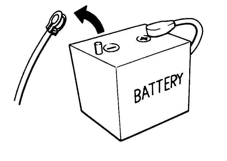
PRECAUTIONS FOR REMOVING BATTERY TERMINAL : Precautions
-
With the adoption of Auto ACC function, ACC power is automatically supplied by operating the Intelligent Key or remote keyless entry or by opening/closing the driver side door. In addition, ACC power is supplied even after the ignition switch is turned to the OFF position, i.e. ACC power is supplied for a certain fixed time.
-
When disconnecting the 12V battery terminal, turn off the ACC power before disconnecting the 12V battery terminal, observing “How to disconnect 12V battery terminal” described below.
 NOTE:
NOTE:
Some ECUs operate for a certain fixed time even after ignition switch is turned OFF and ignition power supply is stopped. If the battery terminal is disconnected before ECU stops, accidental DTC detection or ECU data damage may occur.
-
For Nissan Pathfinder vehicles with the 2-batteries, be sure to connect the main battery and the sub battery before turning ON the ignition switch.
 NOTE:
NOTE:
If the ignition switch is turned ON with any one of the terminals of main battery and sub battery disconnected, then DTC may be detected.
-
After installing the 12V battery, always check "Self Diagnosis Result" of all ECUs and erase DTC.
 NOTE:
NOTE:
The removal of 12V battery may cause a DTC detection error.
HOW TO DISCONNECT 12V BATTERY TERMINAL
Disconnect 12V battery terminal according to instruction described below.
-
Open the hood.
-
Turn ignition switch to the ON position.
-
Turn ignition switch to the OFF position with the driver side door opened.
-
Get out of the Nissan Pathfinder vehicle and close the driver side door.
-
Wait at least 3 minutes.
CAUTION:
While waiting, never operate the Nissan Pathfinder vehicle such as locking, opening, and closing doors. Violation of this caution results in the activation of ACC power supply according to the Auto ACC function.
-
Remove 12V battery terminal.
CAUTION:
After installing 12V battery, always check self-diagnosis results of all ECUs and erase DTC.
Ecu Diagnosis Information. Can Gateway Nissan Pathfinder 5th Gen
8ch Can Gateway
Physical Values
TERMINAL LAYOUT
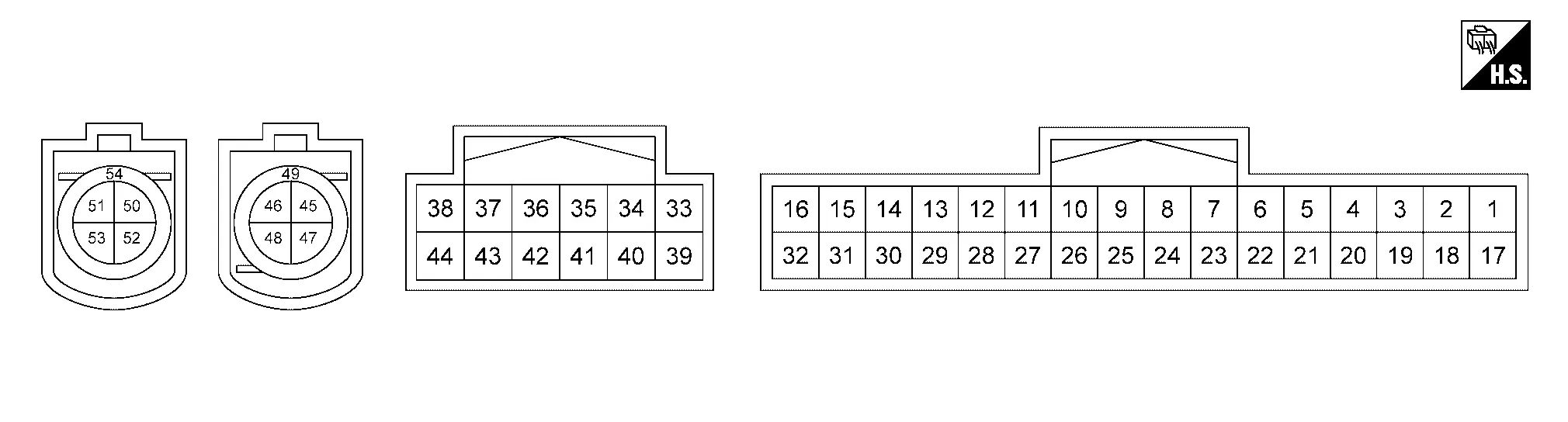
PHYSICAL VALUES
|
Terminal No. (Wire color) | Description | Condition | Standard | Reference value | |||
|---|---|---|---|---|---|---|---|
| + | – | Signal name | Input/ Output | ||||
|
1 (BG) |
21 (B) 28 (B) |
Battery power supply | Input | Ignition switch OFF | 6 – 16 V | Battery voltage | |
|
2 (W) |
— | Diagnostic CAN communication-L | Input/ Output | — | — | — | |
|
3 (L) |
— | Diagnostic CAN communication-H | Input/ Output | — | — | — | |
|
4 (W) |
— | Diagnostic CAN communication-L | Input/ Output | — | — | — | |
|
5 (L) |
— | Diagnostic CAN communication-H | Input/ Output | — | — | — | |
|
6 (R) |
— | Drivetrain CAN communication 2-L | Input/ Output | — | — | — | |
|
7 (GR) |
— | Drivetrain CAN communication 2-H | Input/ Output | — | — | — | |
|
10 (G) |
— | Chassis CAN communication 3-L | Input/ Output | — | — | — | |
|
11 (GR) |
— | Chassis CAN communication 3-H | Input/ Output | — | — | — | |
|
15 (G) |
— | — | — | — | — | — | |
|
16 (R) |
— | — | — | — | — | — | |
|
17 (BG) |
21 (B) 28 (B) |
Ignition power supply | Input | Ignition switch ON | 7 – 16 V | Battery voltage | |
|
18 (P) |
21 (B) 28 (B) |
Accessory power supply | Input | Ignition switch ACC | 7 – 16 V | Battery voltage | |
|
19 (LA/SB)*1 (SB)*2 |
— | IT CAN communication-H | Input/ Output | — | — | — | |
|
20 (LA/V)*1 (V)*2 |
— | IT CAN communication-L | Input/ Output | — | — | — | |
|
21 (B) |
Ground | Ground | — | Ignition switch ON | — | Approx. 0 V | |
|
22 (SB) |
— | IT CAN communication-H | Input/ Output | — | — | — | |
|
23 (V) |
— | IT CAN communication-L | Input/ Output | — | — | — | |
|
28 (B) |
Ground | Ground | — | Ignition switch ON | — | Approx. 0 V | |
|
29 (LG) |
— | — | — | — | — | — | |
|
30 (W) |
— | — | — | — | — | — | |
|
31 (B) |
— | — | — | — | — | — | |
|
33 (L) |
— | Nissan Pathfinder Vehicle CAN communication 3-H | Input/ Output | — | — | — | |
|
34 (P) |
— | Nissan Pathfinder Vehicle CAN communication 3-L | Input/ Output | — | — | — | |
|
35 (BR) |
— | IT CAN communication 1-H | Input/ Output | — | — | — | |
|
36 (P) |
— | IT CAN communication 1-L | Input/ Output | — | — | — | |
|
37 (BR) |
— | ITS CAN communication 4-H | Input/ Output | — | — | — | |
|
38 (W) |
— | ITS CAN communication 4-L | Input/ Output | — | — | — | |
|
41 (W) |
— | IT CAN communication 4-L | Input/ Output | — | — | — | |
|
42 (BR) |
— | IT CAN communication 4-H | Input/ Output | — | — | — | |
|
43 (P) |
— | ITS CAN communication 1-L | Input/ Output | — | — | — | |
|
44 (BR) |
— | ITS CAN communication 1-H | Input/ Output | — | — | — | |
|
47 (G) |
— | Ethernet (-) | — | — | — | — | |
|
48 (Y) |
— | Ethernet (+) | — | — | — | — | |
|
49 (Shield) |
— | Shield | — | — | — | — | |
|
52 (G) |
— | Ethernet (-) | — | — | — | — | |
|
53 (Y) |
— | Ethernet (+) | — | — | — | — | |
|
54 (Shield) |
— | Shield | — | — | — | — | |
*1: With BOSE audio system
*2: Without BOSE audio system
Fail-safe
| DTC | Display contents of CONSULT | Fail-safe condition |
|---|---|---|
| B2600-42 | CONFIG ERROR |
8CH CAN gateway stops transmitting and receiving the following.
|
| B2600-46 | CONFIG ERROR |
8CH CAN gateway stops transmitting and receiving the following.
|
| B2600-49 | CONFIG ERROR |
8CH CAN gateway stops transmitting and receiving the following.
|
| B2600-56 | CONFIG ERROR | — |
| U1325-54 | CONFIG INCOMPLETION |
8CH CAN gateway stops transmitting and receiving the following.
|
| U2340-87 | CAN COMM CIRCUIT | System continue normal control. |
| U2448-87 | CAN COMM CIRCUIT | System continue normal control. |
| U254F-87 | CAN COMM CIRCUIT | System continue normal control. |
| U255B-87 | CAN COMM CIRCUIT | System continue normal control. |
| U278C-88 | ETHERNET PORT1 FAILURE | 8CH CAN gateway stops transmitting and receiving ethernet communication signals between ethernet communication circuit which cannot communicate. |
| U288C-88 | ETHERNET PORT2 FAILURE | 8CH CAN gateway stops transmitting and receiving ethernet communication signals between ethernet communication circuit which cannot communicate. |
DTC Inspection Priority Chart
If some DTCs are displayed at the same time, perform inspections one by one based on the following priority chart.
| Priority | DTC |
|---|---|
| 1 |
|
| 2 |
|
| 3 |
|
DTC Index
Self Diagnostic Result
| DTC | CONSULT display | Reference |
|---|---|---|
| — |
No DTC is detected. Further testing may be required. |
— |
| B2600-42 | CONFIG ERROR | DTC Description |
| B2600-46 | CONFIG ERROR | DTC Description |
| B2600-49 | CONFIG ERROR | DTC Description |
| B2600-56 | CONFIG ERROR | DTC Description |
| U1325-54 | CONFIG INCOMPLETION | DTC Description |
| U278C-88 | ETHERNET PORT1 FAILURE | DTC Description |
| U288C-88 | ETHERNET PORT2 FAILURE | DTC Description |
Network-DTC
| DTC | CONSULT display | Reference |
|---|---|---|
| — |
No DTC is detected. Further testing may be required. |
— |
| U2340-87 | CAN COMM CIRCUIT | DTC Description |
| U2448-87 | CAN COMM CIRCUIT | DTC Description |
| U254F-87 | CAN COMM CIRCUIT | DTC Description |
| U255B-87 | CAN COMM CIRCUIT | DTC Description |
Basic Inspection. Additional Service When Replacing Can Gateway Nissan Pathfinder
8ch Can Gateway
Work Procedure
DESCRIPTION
When replacing 8CH CAN gateway, the following procedure must be performed.
WORK PROCEDURE
SAVE 8CH CAN GATEWAY PART NUMBER
 CONSULT Configuration
Read out the part number from the old 8CH CAN gateway and save the number, following the programming instructions. Refer to “CONSULT Operation Manual”.
 NOTE:
NOTE:
-
The 8CH CAN gateway part number is saved in CONSULT.
-
Even when 8CH CAN gateway part number is not saved in CONSULT, go to 2.
>>
GO TO 2.
REPLACE 8CH CAN GATEWAY
Replace 8CH CAN gateway. Refer to Removal and Installation.
>>
GO TO 3.
PERFORM 8CH CAN GATEWAY PROGRAMMING
 CONSULT Configuration
Perform the 8CH CAN gateway programming. Refer to “CONSULT Operation Manual”.
>>
GO TO 4.
CHECK ALL ECU SELF-DIAGNOSIS RESULTS
-
Erase all ECU self-diagnosis results using CONSULT.
-
Turn the ignition switch OFF.
-
Turn the ignition switch ON and wait for 2 seconds or more.
-
Check that all ECU self-diagnosis results have no DTC (e.g. U1000 and U1001) of CAN communication.
>>
WORK END
Removal and Installation. 8ch Can Gateway Nissan Pathfinder 5th Gen
Removal and Installation
CAUTION:
If replacing CAN gateway, perform "ADDITIONAL SERVICE WHEN REPLACING CAN GATEWAY". Refer to Work Procedure.
REMOVAL
Remove side ventilator duct (RH). Refer to Removal and Installation (RH).
Remove side ventilator duct (LH). Refer to Removal and Installation (LH).
Disconnect 8CH CAN gateway connector.
Remove nuts (A) then remove 8CH CAN gateway (1).
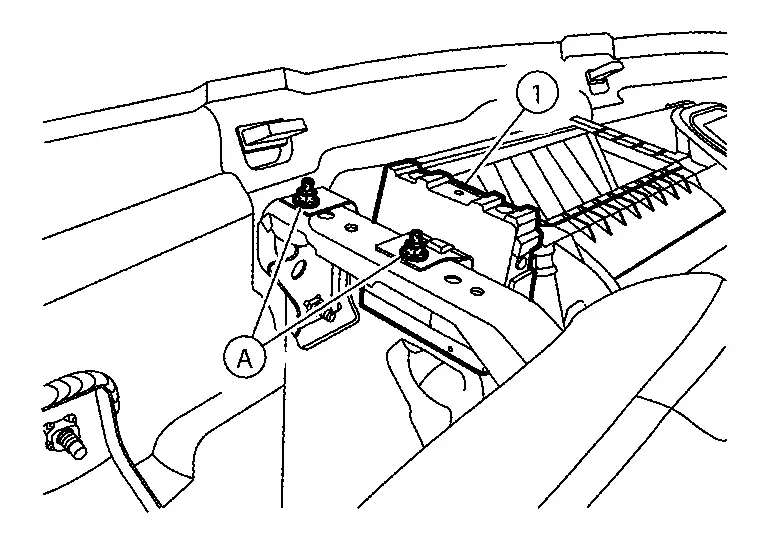
INSTALLATION
Install in the reverse order of removal.
CAUTION:
If replacing CAN gateway, perform "ADDITIONAL SERVICE WHEN REPLACING CAN GATEWAY". Refer to Work Procedure.

Nissan Pathfinder (R53) 2022-2026 Service Manual
Can Gateway
- Precautions
- Ecu Diagnosis Information. Can Gateway
- Basic Inspection. Additional Service When Replacing Can Gateway
- Removal and Installation. 8ch Can Gateway
Contact Us
Nissan Pathfinder Info Center
Email: info@nipathfinder.com
Phone: +1 (800) 123-4567
Address: 123 Pathfinder Blvd, Nashville, TN 37214, USA
Working Hours: Mon–Fri, 9:00 AM – 5:00 PM (EST)
