Nissan Pathfinder: Lan System - Can
How to Use This Manual. How to Use This Section Nissan Pathfinder Fifth generation
Caution
-
This section describes information peculiar to a vehicle and inspection procedures.
-
For trouble diagnosis procedure, refer to Trouble Diagnosis Flow Chart.
Abbreviation List
Unit name abbreviations in CONSULT CAN diagnosis and in this section are as per the following list.
| Abbreviation | Unit name |
|---|---|
| 4WD | 4WD control unit |
| 8ch GW 2 | 8CH CAN gateway |
| A-AMP. | BOSE speaker amp. |
| A-BAG | Air bag diagnosis sensor unit |
| ABS | ABS actuator and electric unit (control unit) |
| ADP | Driver seat control unit |
| AV | AV control unit |
| AVM | Around view monitor control unit |
| BCM | BCM |
| CCM | Chassis control module |
| DLC | Data link connector |
| E-HUD | Head Up Display unit |
| E-SHIFT | Electric shift control module |
| ECM | ECM |
| EPS/DAST 3 | EPS control unit |
| EVTC | Electric intake valve timing control module |
| HFM | Intelligent Key unit |
| HVAC | A/C auto amp. |
| ICC 2 | ADAS control unit 2 |
| IPDM-E | IPDM E/R |
| IVC | TCU |
| LANE | Front camera unit |
| LASER | Distance sensor |
| M&A | Combination meter |
| PWBD | Automatic back door control unit |
| RDR-L | Side radar LH |
| RDR-R | Side radar RH |
| SC CM | Automatic drive positioner control unit |
| SONAR | Sonar control unit |
| STRG | Steering angle sensor |
| TCM | TCM |
| WL CHG | Wireless charger unit |
Precautions Nissan Pathfinder 2026
PRECAUTIONS FOR SUPPLEMENTAL RESTRAINT SYSTEM (SRS) AIR BAG AND SEAT BELT PRE-TENSIONER : Precautions
The Supplemental Restraint System such as “AIR BAG” and “SEAT BELT PRE-TENSIONER”, used along with a front seat belt, helps to reduce the risk or severity of injury to the driver and front passenger for certain types of collisions.
Information necessary to service the system safely is included in the “SRS AIR BAG” and “SEAT BELT” sections of this Service Manual.
WARNING:
Always observe the following items for preventing accidental activation:
-
To avoid rendering the SRS inoperative, which could increase the risk of personal injury or death in the event of a collision that would result in air bag inflation, it is recommended that all maintenance and repair be performed by an authorized NISSAN/INFINITI dealer.
-
Improper repair, including incorrect removal and installation of the SRS, can lead to personal injury caused by unintentional activation of the system. For removal of Spiral Cable and Air Bag Module, see “SRS AIR BAG”.
-
Never use electrical test equipment on any circuit related to the SRS unless instructed to in this Service Manual. SRS wiring harnesses can be identified by yellow and/or orange harnesses or harness connectors.
PRECAUTIONS WHEN USING POWER TOOLS (AIR OR ELECTRIC) AND HAMMERS
WARNING:
Always observe the following items for preventing accidental activation:
-
When working near the Air Bag Diagnosis Sensor Unit or other Air Bag System sensors with the ignition/power switch ON or engine running, never use air or electric power tools or strike near the sensor(s) with a hammer. Heavy vibration could activate the sensor(s) and deploy the air bag(s), possibly causing serious injury.
-
When using air or electric power tools or hammers, always place the ignition/power switch in the OFF position, disconnect the 12V battery or batteries, and wait at least 3 minutes before performing any service.
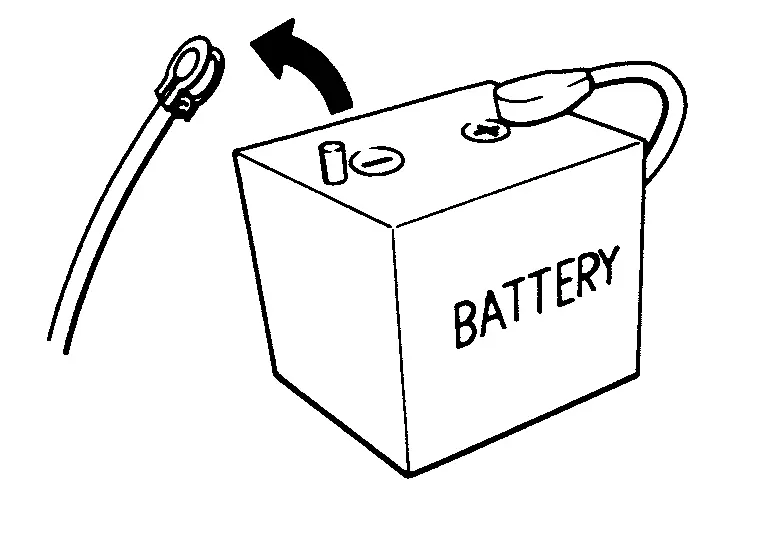
PRECAUTIONS FOR REMOVING BATTERY TERMINAL : Precautions
-
With the adoption of Auto ACC function, ACC power is automatically supplied by operating the Intelligent Key or remote keyless entry or by opening/closing the driver side door. In addition, ACC power is supplied even after the ignition switch is turned to the OFF position, i.e. ACC power is supplied for a certain fixed time.
-
When disconnecting the 12V battery terminal, turn off the ACC power before disconnecting the 12V battery terminal, observing “How to disconnect 12V battery terminal” described below.
 NOTE:
NOTE:
Some ECUs operate for a certain fixed time even after ignition switch is turned OFF and ignition power supply is stopped. If the battery terminal is disconnected before ECU stops, accidental DTC detection or ECU data damage may occur.
-
For Nissan Pathfinder vehicles with the 2-batteries, be sure to connect the main battery and the sub battery before turning ON the ignition switch.
 NOTE:
NOTE:
If the ignition switch is turned ON with any one of the terminals of main battery and sub battery disconnected, then DTC may be detected.
-
After installing the 12V battery, always check "Self Diagnosis Result" of all ECUs and erase DTC.
 NOTE:
NOTE:
The removal of 12V battery may cause a DTC detection error.
HOW TO DISCONNECT 12V BATTERY TERMINAL
Disconnect 12V battery terminal according to instruction described below.
-
Open the hood.
-
Turn ignition switch to the ON position.
-
Turn ignition switch to the OFF position with the driver side door opened.
-
Get out of the Nissan Pathfinder vehicle and close the driver side door.
-
Wait at least 3 minutes.
CAUTION:
While waiting, never operate the Nissan Pathfinder vehicle such as locking, opening, and closing doors. Violation of this caution results in the activation of ACC power supply according to the Auto ACC function.
-
Remove 12V battery terminal.
CAUTION:
After installing 12V battery, always check self-diagnosis results of all ECUs and erase DTC.
Precautions for Trouble Diagnosis
CAUTION:
-
Never apply 7.0 V or more to the measurement terminal.
-
Use a tester with open terminal voltage of 7.0 V or less.
-
Turn the ignition switch OFF and disconnect the battery cable from the negative terminal when checking the harness.
Precautions for Harness Repair
-
Solder the repaired area and wrap tape around the soldered area.
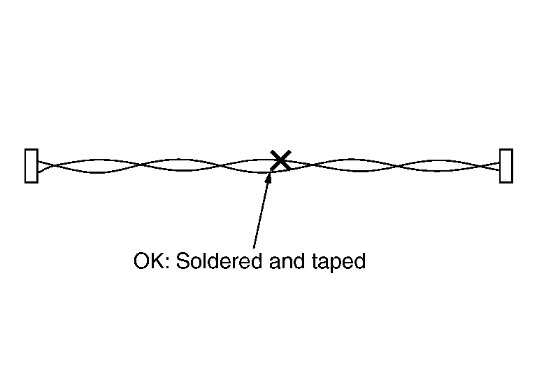
 NOTE:
NOTE:
A fray of twisted lines must be within 110 mm (4.33 in).
-
Bypass connection is never allowed at the repaired area.
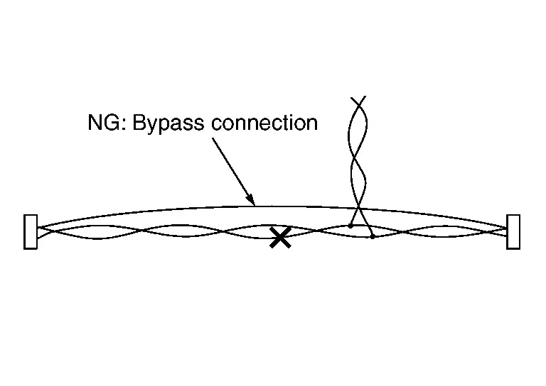
 NOTE:
NOTE:
Bypass connection may cause CAN communication error. The spliced wire becomes separated and the characteristics of twisted line are lost.
-
Replace the applicable harness as an assembly if error is detected on the shield lines of CAN communication line.
Wiring Diagram. Can System Nissan Pathfinder Fifth generation
Wiring Diagram
CAN SYSTEM
Refer to Wiring Diagram.

Nissan Pathfinder (R53) 2022-2026 Service Manual
Can
Contact Us
Nissan Pathfinder Info Center
Email: info@nipathfinder.com
Phone: +1 (800) 123-4567
Address: 123 Pathfinder Blvd, Nashville, TN 37214, USA
Working Hours: Mon–Fri, 9:00 AM – 5:00 PM (EST)
