Nissan Pathfinder: Driver Assistance System - Adas Control Unit 2
- Precautions
- Ecu Diagnosis Information. Adas Control Unit 2
- Removal and Installation. Adas Control Unit 2
Precautions Nissan Pathfinder 2022
Precaution for Supplemental Restraint System (SRS) "AIR BAG" and "SEAT BELT PRE-TENSIONER"
The Supplemental Restraint System such as “AIR BAG” and “SEAT BELT PRE-TENSIONER”, used along with a front seat belt, helps to reduce the risk or severity of injury to the driver and front passenger for certain types of collisions.
Information necessary to service the system safely is included in the “SRS AIR BAG” and “SEAT BELT” sections of this Service Manual.
WARNING:
Always observe the following items for preventing accidental activation:
-
To avoid rendering the SRS inoperative, which could increase the risk of personal injury or death in the event of a collision that would result in air bag inflation, it is recommended that all maintenance and repair be performed by an authorized NISSAN/INFINITI dealer.
-
Improper repair, including incorrect removal and installation of the SRS, can lead to personal injury caused by unintentional activation of the system. For removal of Spiral Cable and Air Bag Module, see “SRS AIR BAG”.
-
Never use electrical test equipment on any circuit related to the SRS unless instructed to in this Service Manual. SRS wiring harnesses can be identified by yellow and/or orange harnesses or harness connectors.
PRECAUTIONS WHEN USING POWER TOOLS (AIR OR ELECTRIC) AND HAMMERS
WARNING:
Always observe the following items for preventing accidental activation:
-
When working near the Air Bag Diagnosis Sensor Unit or other Air Bag System sensors with the ignition/power switch ON or engine running, never use air or electric power tools or strike near the sensor(s) with a hammer. Heavy vibration could activate the sensor(s) and deploy the air bag(s), possibly causing serious injury.
-
When using air or electric power tools or hammers, always switch the ignition/power switch OFF, disconnect the 12V battery or batteries, and wait at least 3 minutes before performing any service.
Precautions For Harness Repair
ITS communication uses a twisted pair line. Be careful when repairing it.
-
Solder the repaired area and wrap tape around the soldered area.
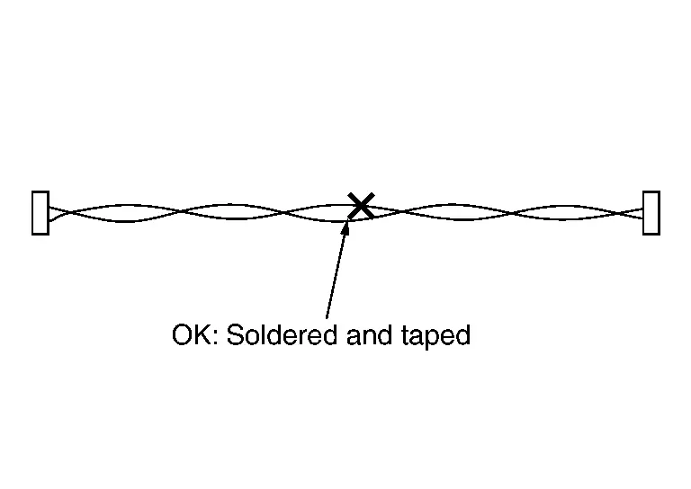
 NOTE:
NOTE:
A fray of twisted lines must be within 110 mm (4.33 in).
-
Bypass connection is never allowed at the repaired area.
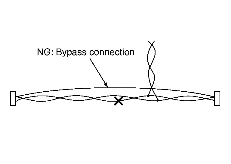
 NOTE:
NOTE:
Bypass connection may cause ITS communication error. The spliced wire becomes separated and the characteristics of twisted line are lost.
Ecu Diagnosis Information. Adas Control Unit 2 Nissan Pathfinder 2026
Without Propilot Assist System
Reference Value
VALUES ON THE DIAGNOSIS TOOL
 NOTE:
NOTE:
The following table includes information (items) inapplicable to this Nissan Pathfinder vehicle. For information (items) applicable to this vehicle, refer to CONSULT display items.
| Monitor item | Condition | Value/Status | |
|---|---|---|---|
| Current malfunction | Ignition switch ON | Displays DTC detected as the current malfunction | |
| PWR SUP MONI | Ignition switch ON | 10 – 16 V | |
| Ignition switch | Ignition switch ON | ON | |
| MAIN SW | Ignition switch ON | When MAIN switch is pressed | ON |
| When MAIN switch is not pressed | OFF | ||
| CANCEL SW | Ignition switch ON | When CANCEL switch is pressed | ON |
| When CANCEL switch is not pressed | OFF | ||
| SET/COAST SW | Ignition switch ON | When SET– switch is pressed | ON |
| When SET– switch is not pressed | OFF | ||
| RESUME/ACC SW | Ignition switch ON | When RES+ switch is pressed | ON |
| When RES+ switch is not pressed | OFF | ||
| DISTANCE SW | Ignition switch ON | When DISTANCE switch is pressed | ON |
| When DISTANCE switch is not pressed | OFF | ||
| Switch2 |
The item is displayed, but it is not used |
— | |
| BRAKE SW | Ignition switch ON | When brake pedal is not depressed | ON |
| When brake pedal is depressed | OFF | ||
| IDLE SW | Engine running | Idling | ON |
| Except idling (depress accelerator pedal) | OFF | ||
| STOP LAMP SW |
The item is displayed, but it is not used |
— | |
| DRIVE MODE STATS |
The item is displayed, but it is not used |
— | |
| G (vertical) |
The item is displayed, but it is not used |
— | |
| G (lateral) |
The item is displayed, but it is not used |
— | |
| Nissan Pathfinder Vehicle speed | While driving | Almost the same speed as speedometer indication | |
| SET VHCL SPD | When Nissan Pathfinder vehicle speed is set | Displays the set vehicle speed | |
| EPS ST angle command value |
The item is displayed, but it is not used |
— | |
| EPS status |
The item is displayed, but it is not used |
— | |
| EPS control request |
The item is displayed, but it is not used |
— | |
| Vibration motor open status |
The item is displayed, but it is not used |
— | |
| ENGINE RPM | Engine running | Almost the same speed as the tachometer indication | |
| THRTL OPENING | Engine running | 0 - 100 % | |
| GEAR |
The item is displayed, but it is not used |
— | |
| CLUTCH SW SIG |
The item is displayed, but it is not used |
— | |
| Neutral switch |
The item is displayed, but it is not used |
— | |
| Parking brake holding request |
The item is displayed, but it is not used |
— | |
| Parking brake release request |
The item is displayed, but it is not used |
— | |
| Wiper signal | Ignition switch ON | When wiper LO is operating | Low |
| When wiper HI is operating | High | ||
| Turn signal | Ignition switch ON | Turn signal is OFF | OFF |
| Turn signal LH is operating | LH | ||
| Turn signal RH is operating | RH | ||
| SET DISTANCE | ICC system ON and press the DISTANCE switch to change the Nissan Pathfinder vehicle-to-vehicle distance setting | When set to “long” | Long |
| When set to “middle” | Mid | ||
| When set to “short” | Short | ||
| Own Nissan Pathfinder vehicle mark |
The item is displayed, but it is not used |
— | |
| VHCL AHEAD | Drive the Nissan Pathfinder vehicle and activate the vehicle-to-vehicle distance control mode | When a vehicle ahead is detected (Nissan Pathfinder vehicle ahead detection indicator ON) | ON |
| When a Nissan Pathfinder vehicle ahead is not detected (vehicle ahead detection indicator OFF) | OFF | ||
| Vhcl ahead recognition | Drive the Nissan Pathfinder vehicle and activate the vehicle-to-vehicle distance control mode | When a vehicle ahead is detected | OK |
| When a Nissan Pathfinder vehicle ahead is not detected | NG | ||
| CRUISE LAMP |
The item is displayed, but it is not used |
— | |
| CRUISE OPE | Drive the Nissan Pathfinder vehicle and activate the vehicle-to-vehicle distance control mode | When ICC system is controlling | ON |
| When ICC system is not controlling | OFF | ||
| FEB SELECT | Ignition switch ON | When AEB is ON | ON |
| When AEB is OFF | OFF | ||
| LDW SELECT | Ignition switch ON | When LDW is ON | ON |
| When LDW is OFF | OFF | ||
| LDP SELECT | Ignition switch ON | When I-LI is ON | ON |
| When I-LI is OFF | OFF | ||
| Steering assist function select |
The item is displayed, but it is not used |
— | |
| FEB SW |
The item is displayed, but it is not used |
— | |
| ICC warning output | Ignition switch ON | ICC malfunction message: ON | ON |
| ICC malfunction message: OFF | OFF | ||
| Speed control mode | Ignition switch ON | When the Nissan Pathfinder vehicle-to-vehicle distance control mode is operating | ICC |
| When the conventional (fixed speed) cruise control mode is operating | ASCD | ||
| When the cruise control mode is OFF | OFF | ||
| Set display lamp | Ignition switch ON | When the Nissan Pathfinder vehicle-to-vehicle distance control mode system display is ON | ICC |
| When the conventional (fixed speed) cruise control mode system display is ON | ASCD | ||
| When the cruise control mode system display is OFF | OFF | ||
| LDP system |
The item is displayed, but it is not used |
— | |
| LDP control | Ignition switch ON | I-LI system is malfunctioning | ABNML |
| I-LI system is normal | NRML | ||
| LDW system | Ignition switch ON | When LDW is ON | ON |
| When LDW is OFF | OFF | ||
| Steering torque (measured) |
The item is displayed, but it is not used |
— | |
| Steering torque rgstrtn stats |
The item is displayed, but it is not used |
— | |
| Steering torque error cause |
The item is displayed, but it is not used |
— | |
 NOTE:
NOTE:
 NOTE:
NOTE:
 NOTE:
NOTE:
 NOTE:
NOTE:
 NOTE:
NOTE:
 NOTE:
NOTE:
 NOTE:
NOTE:
 NOTE:
NOTE:
 NOTE:
NOTE:
 NOTE:
NOTE:
 NOTE:
NOTE:
 NOTE:
NOTE:
 NOTE:
NOTE:
 NOTE:
NOTE:
 NOTE:
NOTE:
 NOTE:
NOTE:
 NOTE:
NOTE:
 NOTE:
NOTE:
 NOTE:
NOTE:
 NOTE:
NOTE:
 NOTE:
NOTE:
 NOTE:
NOTE:
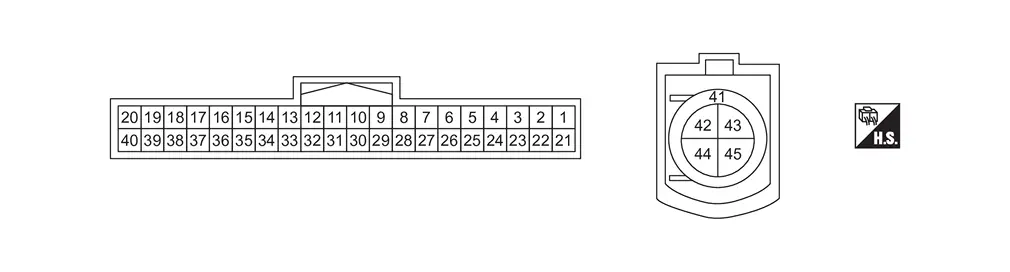
TERMINAL LAYOUT
PHYSICAL VALUES
|
Terminal No. (Wire color) | Description | Condition | Value (Approx.) | |||
|---|---|---|---|---|---|---|
| + | − | Signal name | Input/Output | |||
|
9 (W) |
Ground | Steering assist switch signal | Input | Ignition switch ON | Steering assist switch is not pressed | Battery voltage |
| Steering assist switch is pressed | 0 V | |||||
|
17 (P) |
ITS CAN communication-L | — | — | — | ||
|
20 (R) |
Ignition power supply | Input | Ignition switch ON | Battery voltage | ||
|
28 (BR) |
ITS CAN communication-H | — | — | — | ||
|
29 (W) |
ITS CAN communication-L | — | — | — | ||
|
30 (B) |
Ground | — | Ignition switch ON | 0 V | ||
|
31 (BR) |
ITS CAN communication-H | — | — | — | ||
|
32 (LG) |
ITS CAN communication-L | — | — | — | ||
|
34 (BR) |
ITS CAN communication-H | — | — | — | ||
|
35 (R) |
ITS CAN communication-L | — | — | — | ||
|
37 (BR) |
ITS CAN communication-H | — | — | — | ||
|
41 (SHIELD) |
Shield | — | — | — | ||
|
44 (Y) |
Ethernet(+) | — | — | — | ||
|
45 (G) |
Ethernet(-) | — | — | — | ||
With Propilot Assist System
Reference Value
VALUES ON THE DIAGNOSIS TOOL
 NOTE:
NOTE:
The following table includes information (items) inapplicable to this Nissan Pathfinder vehicle. For information (items) applicable to this vehicle, refer to CONSULT display items.
| Monitor item | Condition | Value/Status | |
|---|---|---|---|
| Current malfunction | Ignition switch ON | Displays DTC detected as the current malfunction | |
| PWR SUP MONI | Ignition switch ON | 10 – 16 V | |
| Ignition switch | Ignition switch ON | ON | |
| MAIN SW | Ignition switch ON | When ProPILOT Assist MAIN switch is pressed | ON |
| When ProPILOT Assist MAIN switch is not pressed | OFF | ||
| CANCEL SW | Ignition switch ON | When CANCEL switch is pressed | ON |
| When CANCEL switch is not pressed | OFF | ||
| SET/COAST SW | Ignition switch ON | When SET– switch is pressed | ON |
| When SET– switch is not pressed | OFF | ||
| RESUME/ACC SW | Ignition switch ON | When RES+ switch is pressed | ON |
| When RES+ switch is not pressed | OFF | ||
| DISTANCE SW | Ignition switch ON | When DISTANCE switch is pressed | ON |
| When DISTANCE switch is not pressed | OFF | ||
| Switch1 | Ignition switch ON | When steering assist switch is pressed | ON |
| When steering assist switch is not pressed | OFF | ||
| Switch2 |
The item is displayed, but it is not used |
— | |
| BRAKE SW | Ignition switch ON | When brake pedal is not depressed | ON |
| When brake pedal is depressed | OFF | ||
| IDLE SW | Engine running | Idling | ON |
| Except idling (depress accelerator pedal) | OFF | ||
| STOP LAMP SW |
The item is displayed, but it is not used |
— | |
| DRIVE MODE STATS |
The item is displayed, but it is not used |
— | |
| G (vertical) |
The item is displayed, but it is not used |
— | |
| G (lateral) |
The item is displayed, but it is not used |
— | |
| Nissan Pathfinder Vehicle speed | While driving | Almost the same speed as speedometer indication | |
| SET VHCL SPD | When Nissan Pathfinder vehicle speed is set | Displays the set vehicle speed | |
| EPS ST angle command value |
The item is displayed, but it is not used |
— | |
| EPS status |
The item is displayed, but it is not used |
— | |
| EPS control request |
The item is displayed, but it is not used |
— | |
| Vibration motor open status |
The item is displayed, but it is not used |
— | |
| ENGINE RPM | Engine running | Almost the same speed as the tachometer indication | |
| THRTL OPENING | Engine running | 0 - 100 % | |
| GEAR |
The item is displayed, but it is not used |
— | |
| CLUTCH SW SIG |
The item is displayed, but it is not used |
— | |
| Neutral switch |
The item is displayed, but it is not used |
— | |
| Parking brake holding request |
The item is displayed, but it is not used |
— | |
| Parking brake release request |
The item is displayed, but it is not used |
— | |
| Wiper signal | Ignition switch ON | When wiper LO is operating | Low |
| When wiper HI is operating | High | ||
| Turn signal | Ignition switch ON | Turn signal is OFF | OFF |
| Turn signal LH is operating | LH | ||
| Turn signal RH is operating | RH | ||
| SET DISTANCE | ProPILOT Assist system ON and press the DISTANCE switch to change the Nissan Pathfinder vehicle-to-vehicle distance setting | When set to “long” | Long |
| When set to “middle” | Mid | ||
| When set to “short” | Short | ||
| Own Nissan Pathfinder vehicle mark |
The item is displayed, but it is not used |
— | |
| VHCL AHEAD | Drive the Nissan Pathfinder vehicle and activate the vehicle-to-vehicle distance control mode | When a vehicle ahead is detected (Nissan Pathfinder vehicle ahead detection indicator ON) | ON |
| When a Nissan Pathfinder vehicle ahead is not detected (vehicle ahead detection indicator OFF) | OFF | ||
| Vhcl ahead recognition | Drive the Nissan Pathfinder vehicle and activate the vehicle-to-vehicle distance control mode | When a vehicle ahead is detected | OK |
| When a Nissan Pathfinder vehicle ahead is not detected | NG | ||
| CRUISE LAMP |
The item is displayed, but it is not used |
— | |
| CRUISE OPE | Drive the Nissan Pathfinder vehicle and activate the vehicle-to-vehicle distance control mode | When ProPILOT Assist system is controlling | ON |
| When ProPILOT Assist system is not controlling | OFF | ||
| Pro Pirot ON/OFF request |
The item is displayed, but it is not used |
— | |
| FEB SELECT | Ignition switch ON | When AEB is ON | ON |
| When AEB is OFF | OFF | ||
| LDW SELECT | Ignition switch ON | When LDW is ON | ON |
| When LDW is OFF | OFF | ||
| LDP SELECT | Ignition switch ON | When I-LI is ON | ON |
| When I-LI is OFF | OFF | ||
| Steering assist function select | Ignition switch ON | When Steering assist function is ON | ON |
| When Steering assist function is OFF | OFF | ||
| FEB SW |
The item is displayed, but it is not used |
— | |
| ICC warning output | Ignition switch ON | ProPILOT Assist malfunction message: ON | ON |
| ProPILOT Assist malfunction message: OFF | OFF | ||
| Speed control mode | Ignition switch ON | When the Nissan Pathfinder vehicle-to-vehicle distance control mode is operating | ICC |
| When the conventional (fixed speed) cruise control mode is operating | ASCD | ||
| When the cruise control mode is OFF | OFF | ||
| Set display lamp | Ignition switch ON | When the Nissan Pathfinder vehicle-to-vehicle distance control mode system display is ON | ICC |
| When the conventional (fixed speed) cruise control mode system display is ON | ASCD | ||
| When the cruise control mode system display is OFF | OFF | ||
| LDP system |
The item is displayed, but it is not used |
— | |
| LDP control | Ignition switch ON | I-LI system is malfunctioning | ABNML |
| I-LI system is normal | NRML | ||
| LDW system | Ignition switch ON | When LDW is ON | ON |
| When LDW is OFF | OFF | ||
| Steering torque (measured) |
The item is displayed, but it is not used |
— | |
| Steering torque rgstrtn stats |
The item is displayed, but it is not used |
— | |
| Steering torque error cause |
The item is displayed, but it is not used |
— | |
 NOTE:
NOTE:
 NOTE:
NOTE:
 NOTE:
NOTE:
 NOTE:
NOTE:
 NOTE:
NOTE:
 NOTE:
NOTE:
 NOTE:
NOTE:
 NOTE:
NOTE:
 NOTE:
NOTE:
 NOTE:
NOTE:
 NOTE:
NOTE:
 NOTE:
NOTE:
 NOTE:
NOTE:
 NOTE:
NOTE:
 NOTE:
NOTE:
 NOTE:
NOTE:
 NOTE:
NOTE:
 NOTE:
NOTE:
 NOTE:
NOTE:
 NOTE:
NOTE:
 NOTE:
NOTE:
 NOTE:
NOTE:
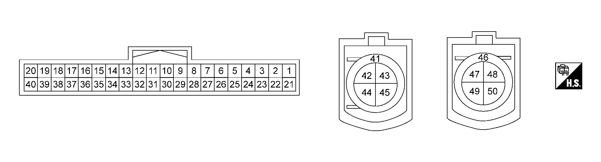
TERMINAL LAYOUT
PHYSICAL VALUES
|
Terminal No. (Wire color) | Description | Condition | Value (Approx.) | |||
|---|---|---|---|---|---|---|
| + | − | Signal name | Input/Output | |||
|
9 (W) |
Ground | Steering assist switch signal | Input | Ignition switch ON | Steering assist switch is not pressed | Battery voltage |
| Steering assist switch is pressed | 0 V | |||||
|
17 (P) |
ITS CAN communication-L | — | — | — | ||
|
20 (R) |
Ignition power supply | Input | Ignition switch ON | Battery voltage | ||
|
28 (BR) |
ITS CAN communication-H | — | — | — | ||
|
29 (W) |
ITS CAN communication-L | — | — | — | ||
|
30 (B) |
Ground | — | Ignition switch ON | 0 V | ||
|
31 (BR) |
ITS CAN communication-H | — | — | — | ||
|
32 (LG) |
ITS CAN communication-L | — | — | — | ||
|
34 (BR) |
ITS CAN communication-H | — | — | — | ||
|
35 (R) |
ITS CAN communication-L | — | — | — | ||
|
37 (BR) |
ITS CAN communication-H | — | — | — | ||
|
41 (SHIELD) |
Shield | — | — | — | ||
|
44 (Y) |
Ethernet(+) | — | — | — | ||
|
45 (G) |
Ethernet(-) | — | — | — | ||
|
46 (SHIELD) |
Shield | — | — | — | ||
|
49 (Y) |
Ethernet(+) | — | — | — | ||
|
50 (G) |
Ethernet(-) | — | — | — | ||
Fail-safe (ADAS Control Unit)
Refer to Fail-safe (ADAS Control Unit 2).
DTC Inspection Priority Chart
If multiple DTCs are detected simultaneously, check them one by one depending on the following DTC inspection priority chart.
| Priority | Detected items (DTC) |
|---|---|
| 1 |
|
| 2 | U1327-54: MAC key update |
| 3 | U1327-52: MAC key update |
| 4 |
|
| 5 |
|
| 6 |
|
DTC Index
×: Applicable
| DTC |
Items (CONSULT screen terms) | Fail-safe | Reference | |||||||||||
|---|---|---|---|---|---|---|---|---|---|---|---|---|---|---|
| Nissan Pathfinder Vehicle-to-vehicle distance control mode | Conventional (fixed speed) cruise control mode | Steering wheel assistance function | AEB | RAB | I-FCW | LDW | I-LI | I-BSI | TSR | I-DA | ||||
| C1F00 | 1C | CONTROL UNIT | × | × | × | × | × | × | × | × | × | × | × | DTC Description |
| 44 | × | × | × | × | × | × | × | × | × | × | × | DTC Description | ||
| 45 | × | × | × | × | × | × | × | × | × | × | × | DTC Description | ||
| 46 | × | × | × | × | × | × | × | × | × | × | × | DTC Description | ||
| 47 | × | × | × | × | × | × | × | × | × | × | × | DTC Description | ||
| 49 | × | × | × | × | × | × | × | × | × | × | × | DTC Description | ||
| 4B | × | × | × | × | × | × | × | × | × | × | × | DTC Description | ||
| 54 | × | × | × | — | — | — | — | — | — | — | — | DTC Description | ||
| 62 | × | × | × | × | × | × | × | × | × | × | × | DTC Description | ||
| 71 | × | × | × | × | × | × | × | × | × | × | × | DTC Description | ||
| 87 | × | × | × | × | × | × | × | × | × | × | × | DTC Description | ||
| C1F02 | 16 | POWER SUPPLY CIR | × | × | × | × | × | × | × | × | × | × | × | DTC Description |
| 17 | × | × | × | × | × | × | × | × | × | × | × | DTC Description | ||
| C1F03 | 23 | OPERATION SW CIRC | × | × | × | — | — | — | — | — | — | — | — | DTC Description |
| 62 | × | × | × | — | — | — | — | — | — | — | — | DTC Description | ||
| 72 | × | × | × | × | × | — | — | — | — | — | — | DTC Description | ||
| 73 | × | × | × | × | × | — | — | — | — | — | — | DTC Description | ||
| C1F04 | 48 | FEB OPE COUNT LIMIT | — | — | — | × | — | — | — | — | — | — | — | DTC Description |
| 61 | × | × | × | × | × | — | — | — | — | — | — | DTC Description | ||
| C1F05 | 49 | Front camera unit | × | × | × | × | — | — | × | × | × | × | — | DTC Description |
| 4B | × | × | × | × | — | — | × | × | × | × | — | DTC Description | ||
| 54 | × | × | × | × | — | — | × | × | × | × | — | DTC Description | ||
| 82 | × | × | × | × | — | — | × | × | × | × | — | DTC Description | ||
| 83 | × | × | × | × | — | — | × | × | × | × | — | DTC Description | ||
| C1F07 | 62 | OPERATION SW CIRC | × | × | × | × | × | × | × | × | × | × | — | DTC Description |
| C1F36 | 55 | CONFIG UNFINISHED | × | × | × | × | × | × | × | × | × | × | × | DTC Description |
| C1F40 | 04 | ECM | × | × | × | × | × | — | × | × | × | × | — | DTC Description |
| 24 | × | × | × | × | × | — | × | × | × | × | — | DTC Description | ||
| 62 | × | × | × | × | × | — | × | × | × | × | — | DTC Description | ||
| 82 | × | × | × | × | × | — | × | × | × | × | — | DTC Description | ||
| 83 | × | × | × | × | × | — | × | × | × | × | — | DTC Description | ||
| C1F41 | 04 | TRANSMISSION CIRCUIT | × | × | × | — | — | — | — | — | — | × | — | DTC Description |
| 84 | × | × | × | × | × | × | × | — | — | × | — | DTC Description | ||
| C1F42 | 82 | TCM | × | × | × | × | × | × | × | — | — | × | — | DTC Description |
| 83 | × | × | × | × | × | × | × | — | — | × | — | DTC Description | ||
| C1F43 | 04 | Around view control unit | — | — | — | — | — | — | — | — | — | — | — | DTC Description |
| 82 | — | — | — | — | — | — | — | — | — | — | — | DTC Description | ||
| 83 | — | — | — | — | — | — | — | — | — | — | — | DTC Description | ||
| C1F44 | 82 | BCM | × | × | × | × | × | — | — | — | — | — | × | DTC Description |
| 83 | × | × | × | × | × | — | — | — | — | — | × | DTC Description | ||
| C1F45 | 82 | CCM | × | × | × | — | — | — | × | — | — | — | — | DTC Description |
| 83 | × | × | × | — | — | — | × | — | — | — | — | DTC Description | ||
| C1F47 | 82 | Combination meter | × | × | × | × | × | × | × | × | × | × | × | DTC Description |
| 83 | × | × | × | × | × | × | × | × | × | × | × | DTC Description | ||
| C1F48 | 04 | ABS/TCS/VDC CIRC | × | × | × | × | × | × | × | × | × | × | — | DTC Description |
| 16 | × | × | × | × | × | × | × | × | × | × | — | DTC Description | ||
| 62 | × | × | × | × | × | × | × | × | × | × | — | DTC Description | ||
| 82 | × | × | × | × | × | × | × | × | × | × | — | DTC Description | ||
| 83 | × | × | × | × | × | × | × | × | × | × | — | DTC Description | ||
| 86 | × | × | × | × | × | × | × | × | × | × | — | DTC Description | ||
| C1F51 | 82 | IPDM E/R | — | — | — | — | — | — | — | — | — | — | — | DTC Description |
| C1F51 | 83 | IPDM E/R | — | — | — | — | — | — | — | — | — | — | — | DTC Description |
| C1F55 | 82 | Electric parking brake circuit | × | × | × | — | — | — | — | — | — | — | — | DTC Description |
| C1F55 | 83 | Electric parking brake circuit | × | × | × | — | — | — | — | — | — | — | — | DTC Description |
| C1F59 | 04 | EPS control unit | × | × | × | — | — | — | — | — | — | — | — | DTC Description |
| C1F59 | 82 | EPS control unit | × | × | × | — | — | — | — | — | — | — | — | DTC Description |
| C1F59 | 83 | EPS control unit | × | × | × | — | — | — | — | — | — | — | — | DTC Description |
| C1F5F | 04 | Distance sensor | × | × | × | × | — | × | — | — | — | — | — | DTC Description |
| C1F5F | 08 | Distance sensor | × | × | × | × | — | × | — | — | — | — | — | DTC Description |
| C1F5F | 16 | Distance sensor | × | × | × | × | — | × | — | — | — | — | — | DTC Description |
| C1F5F | 4B | Distance sensor | × | × | × | × | — | × | — | — | — | — | — | DTC Description |
| C1F5F | 78 | Distance sensor | × | × | × | × | — | × | — | — | — | — | — | DTC Description |
| C1F5F | 82 | Distance sensor | × | × | × | × | — | × | — | — | — | — | — | DTC Description |
| C1F5F | 83 | Distance sensor | × | × | × | × | — | × | — | — | — | — | — | DTC Description |
| C1F65 | 04 | Sonar control unit | — | — | — | — | — | — | — | — | — | — | — | DTC Description |
| C1F65 | 82 | Sonar control unit | — | — | — | — | — | — | — | — | — | — | — | DTC Description |
| C1F65 | 83 | Sonar control unit | — | — | — | — | — | — | — | — | — | — | — | DTC Description |
| C1F70 | 87 | Ethernet circuit | × | × | × | × | × | × | × | × | × | × | × | DTC Description |
| C1F71 | 87 | Ethernet circuit | × | × | × | × | × | × | × | × | × | × | × | DTC Description |
| C1F76 | 49 | Steering angle sensor | × | × | × | × | × | × | × | × | × | × | × | DTC Description |
| C1F76 | 82 | Steering angle sensor | × | × | × | × | × | × | × | × | × | × | × | DTC Description |
| C1F76 | 83 | Steering angle sensor | × | × | × | × | × | × | × | × | × | × | × | DTC Description |
| C1F89 | 04 | Side radar rear LH | — | — | — | — | — | — | — | — | × | — | — | DTC Description |
| C1F89 | 82 | Side radar rear LH | — | — | — | — | — | — | — | — | × | — | — | DTC Description |
| C1F89 | 83 | Side radar rear LH | — | — | — | — | — | — | — | — | × | — | — | DTC Description |
| C1F8A | 04 | Side radar rear RH | — | — | — | — | — | — | — | — | × | — | — | DTC Description |
| C1F8A | 82 | Side radar rear RH | — | — | — | — | — | — | — | — | × | — | — | DTC Description |
| C1F8A | 83 | Side radar rear RH | — | — | — | — | — | — | — | — | × | — | — | DTC Description |
| U2752 | 87 | Ethernet circuit | × | × | × | × | × | × | × | × | × | × | × | DTC Description |
| U2752 | 88 | Ethernet circuit | × | × | × | × | × | × | × | × | × | × | × | DTC Description |
| U2852 | 87 | Ethernet circuit | × | × | × | × | × | × | × | × | × | × | × | DTC Description |
| U2852 | 88 | Ethernet circuit | × | × | × | × | × | × | × | × | × | × | × | DTC Description |
×: Applicable
| DTC |
Items (CONSULT screen terms) | Fail-safe | Reference | |||||||||||
|---|---|---|---|---|---|---|---|---|---|---|---|---|---|---|
| Nissan Pathfinder Vehicle-to-vehicle distance control mode | Conventional (fixed speed) cruise control mode | Steering wheel assistance function | AEB | RAB | I-FCW | LDW | I-LI | I-BSI | TSR | I-DA | ||||
| U2112 | 87 | CAN comm err (brake unit) | × | × | × | × | × | × | × | × | × | × | × | DTC Description |
| U2118 | 87 | CAN comm err (Intelligent Key) | × | × | × | × | × | × | × | × | × | × | × | DTC Description |
| U2140 | 87 | CAN comm err (ECM) | × | × | × | × | × | × | × | × | × | × | × | DTC Description |
| U2148 | 87 | CAN comm err (brake control unit) | × | × | × | × | × | × | × | × | × | × | × | DTC Description |
| U214A | 87 | CAN comm err (AWD/4WD) | × | × | × | × | × | × | × | × | × | × | × | DTC Description |
| U214E | 87 | CAN comm err (combination meter) | × | × | × | × | × | × | × | × | × | × | × | DTC Description |
| U214F | 87 | CAN comm err (BCM) | × | × | × | × | × | × | × | × | × | × | × | DTC Description |
| U2150 | 87 | CAN comm err (AIRBAG) | — | — | — | — | — | — | — | — | — | — | — | DTC Description |
| U2154 | 87 | CAN comm err (MIU) | — | — | — | — | — | — | — | — | — | — | — | DTC Description |
| U2155 | 87 | CAN comm err (parking brake) | × | — | — | — | — | — | — | — | — | — | — | DTC Description |
| U2159 | 87 | CAN comm err (steering control unit) | × | — | × | — | — | — | — | — | — | — | — | DTC Description |
| U2175 | 87 | CAN comm err (AVM) | — | — | — | — | — | — | — | — | — | — | — | DTC Description |
| U2176 | 87 | CAN comm err (CCM) | × | × | × | — | — | — | — | — | — | — | — | DTC Description |
| U226B | 87 | CAN comm err (front camera) | × | × | × | × | — | — | × | × | × | × | — | DTC Description |
| U236C | 87 | CAN comm err (side radar) | — | — | — | — | — | — | — | — | × | — | — | DTC Description |
| U236E | 87 | CAN comm err (side radar) | — | — | — | — | — | — | — | — | × | — | — | DTC Description |
| U2440 | 87 | CAN comm err (ECM) | × | × | × | × | × | × | × | × | × | × | × | DTC Description |
| U2441 | 87 | CAN comm err (TCM) | × | × | × | × | × | × | × | × | × | × | — | DTC Description |
| U2448 | 87 | CAN comm err (ABS control unit) | × | × | × | × | × | × | × | × | × | × | × | DTC Description |
| U244E | 87 | CAN comm err (combination meter) | × | × | × | × | × | × | × | × | × | × | × | DTC Description |
| U244F | 87 | CAN comm err (BCM) | × | × | × | × | × | × | × | × | × | × | × | DTC Description |
| U2454 | 87 | CAN comm err (MIU) | — | — | — | — | — | — | — | — | — | — | — | DTC Description |
| U2456 | 87 | CAN comm err (ST angle sensor) | × | × | × | × | × | × | × | × | × | × | × | DTC Description |
| U2459 | 87 | CAN comm err (EPS control unit) | × | — | × | — | — | — | — | — | — | — | — | DTC Description |
| U245B | 87 | CAN comm err (IPDM E/R) | — | — | — | — | × | — | — | — | — | — | — | DTC Description |
| U2465 | 87 | CAN comm err (sonar control unit) | — | — | — | — | × | — | — | — | — | — | — | DTC Description |
| U2475 | 87 | CAN comm err (AVM) | — | — | — | — | — | — | — | — | — | — | — | DTC Description |
| U2476 | 87 | CAN comm err (CCM) | × | × | × | — | — | — | — | — | — | — | — | DTC Description |
| U2589 | 87 | CAN comm err (side radar) | — | — | — | — | — | — | — | — | × | — | — | DTC Description |
| U258A | 87 | CAN comm err (side radar) | — | — | — | — | — | — | — | — | × | — | — | DTC Description |
| U2A05 | 88 | Comm Bus Off ITS4-FD | — | — | — | — | — | — | — | — | × | — | — | DTC Description |
| U2A07 | 88 | CAN comm err | — | — | — | — | — | — | — | — | × | — | — | DTC Description |
| U2A08 | 88 | Comm Bus Off ITS3-FD | — | — | — | — | — | — | — | — | × | — | — | DTC Description |
| U2A09 | 88 | Comm Bus Off ITS5-FD | — | — | — | — | — | — | — | — | × | — | — | DTC Description |
×: Applicable
| DTC |
Items (CONSULT screen terms) | Fail-safe | Reference | |||||||||||
|---|---|---|---|---|---|---|---|---|---|---|---|---|---|---|
| Nissan Pathfinder Vehicle-to-vehicle distance control mode | Conventional (fixed speed) cruise control mode | Steering wheel assistance function | AEB | RAB | I-FCW | LDW | I-LI | I-BSI | TSR | I-DA | ||||
| U1327 | 52 | MAC key update | × | × | × | × | × | × | × | × | × | × | × | DTC Description |
| U1327 | 54 | MAC key update | × | × | × | × | × | × | × | × | × | × | × | DTC Description |
| U214F | 57 | CAN comm err (BCM) | × | × | × | × | × | × | × | × | × | × | × | DTC Description |
| U2175 | 57 | CAN comm err (AVM) | — | — | — | — | — | — | — | — | — | — | — | DTC Description |
| U2176 | 57 | CAN comm err (CCM/ST angle sensor) | × | × | × | — | — | — | — | — | — | — | — | DTC Description |
| U2440 | 57 | CAN comm err (ECM) | × | × | × | × | × | × | × | × | × | × | × | DTC Description |
| U244F | 57 | CAN comm err (BCM) | × | × | × | × | × | × | × | × | × | × | × | DTC Description |
| U2465 | 57 | CAN comm err (sonar control unit) | — | — | — | — | × | — | — | — | — | — | — | DTC Description |
| U2476 | 57 | CAN comm err (CCM) | × | × | × | — | — | — | — | — | — | — | — | DTC Description |
 NOTE:
NOTE:
With the detection of Network-DTC some systems do not perform the fail-safe operation.
A system controlling based on a signal received from the control unit performs fail-safe operation when the communication with the ADAS control unit 2 becomes inoperable.
Removal and Installation. Adas Control Unit 2 Nissan Pathfinder
Removal and Installation
REMOVAL
CAUTION:
If replacing ADAS control unit 2, perform "ADDITIONAL SERVICE WHEN REPLACING ADAS CONTROL UNIT 2". Refer to Work Procedure.
Disconnect the battery negative terminal. Refer to Battery Disconnect.
Remove center console assembly. Refer to Removal and Installation.
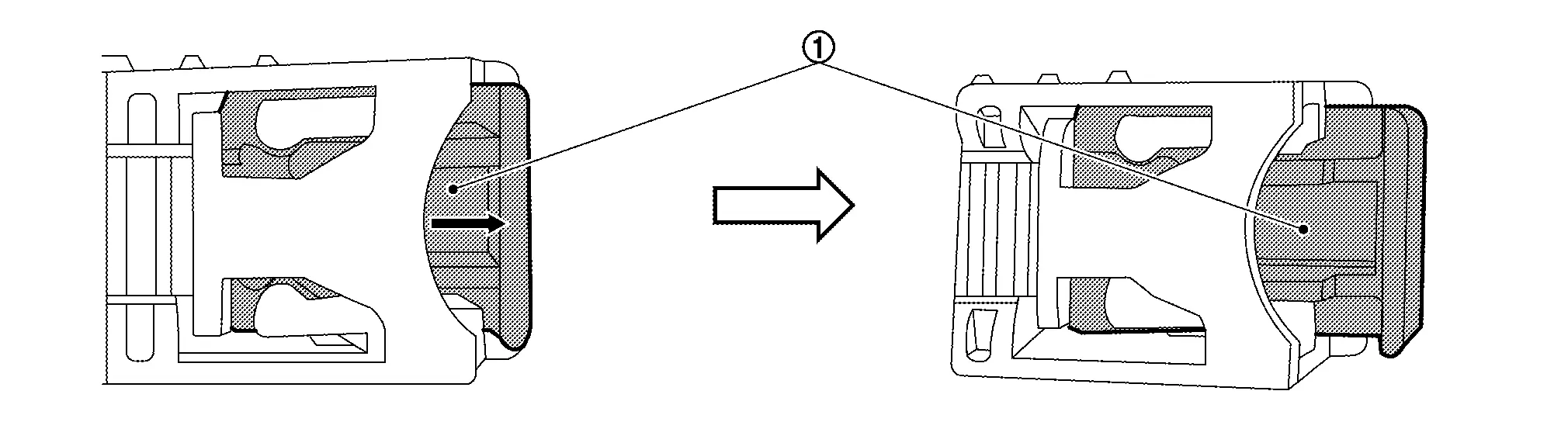
Release the lock (1) as shown by the arrow in the figure and disconnect the harness connectors from the ADAS control unit 2.
Remove nuts (A) and remove ADAS control unit 2 (1).
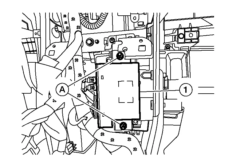
 NOTE:
NOTE:
Part of steering member removed for clarity.
INSTALLATION
Installation is in the reverse order of removal.
-
Tighten ADAS control unit 2 nuts to specification.
ADAS control unit nuts : 8.0 Nm (0.82 kg-m, 71 in-lb)
CAUTION:
If replacing ADAS control unit 2, perform "ADDITIONAL SERVICE WHEN REPLACING ADAS CONTROL UNIT 2". Refer to Work Procedure.

Nissan Pathfinder (R53) 2022-2026 Service Manual
Adas Control Unit 2
- Precautions
- Ecu Diagnosis Information. Adas Control Unit 2
- Removal and Installation. Adas Control Unit 2
Contact Us
Nissan Pathfinder Info Center
Email: info@nipathfinder.com
Phone: +1 (800) 123-4567
Address: 123 Pathfinder Blvd, Nashville, TN 37214, USA
Working Hours: Mon–Fri, 9:00 AM – 5:00 PM (EST)
