Nissan Pathfinder: Transaxle & Transmission - Removal and Installation
- Electric Shift Selector
- Electric Shift Control Module
- Paddle Shifter
- Dog Clutch a Position Sensor
- Tcm
- Idle Stop Sensor
- Air Breather Hose
- Oil Pan ➤
- Control Valve
- A/t Sensor Unit
- Differential Side Oil Seal
- Water Hose
- Fluid Cooler System
- A/t Fluid Warmer
- Plug
Electric Shift Selector Nissan Pathfinder 2022
Exploded View
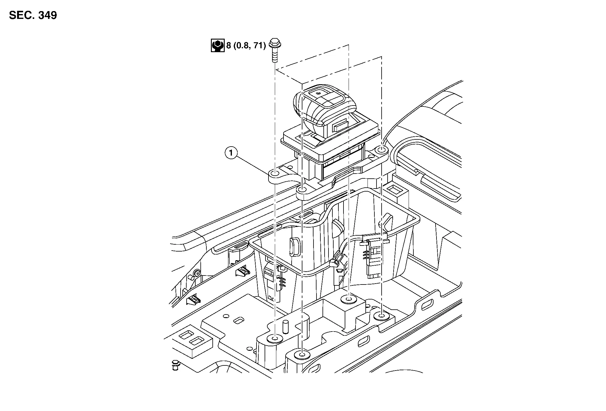
| 1. | Electric shift selector assembly |
Removal and Installation
REMOVAL
Shift the electric shift selector to the park position.
Disconnect the negative terminal from the battery. Refer to Battery Disconnect.
Remove the shift selector finisher. Refer to Exploded View.
CAUTION:
Make sure the Nissan Pathfinder vehicle cannot move with the parking brake applied.
Disconnect the harness connector from the electric shift selector.
Remove the electric shift selector bolts and remove the electric shift selector from center console assembly.
INSTALLATION
Installation is in the reverse order of removal.
Inspection
INSPECTION
Check the A/T position. If a malfunction is found, adjust the A/T position. Refer to Inspection.
Electric Shift Control Module Nissan Pathfinder R53
Exploded View
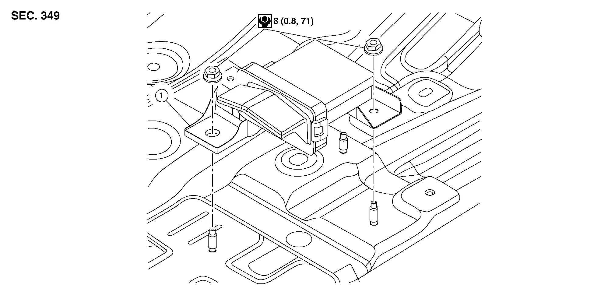
| 1. | Electric shift control module |
Removal and Installation
REMOVAL
Remove center console assembly. Refer to Removal and Installation.
Remove electric shift control module bolts.
Disconnect the harness connector from the electric shift control module and remove the electric shift control module.
INSTALLATION
Installation is in the reverse order of removal.
Paddle Shifter Nissan Pathfinder 2022
Exploded View
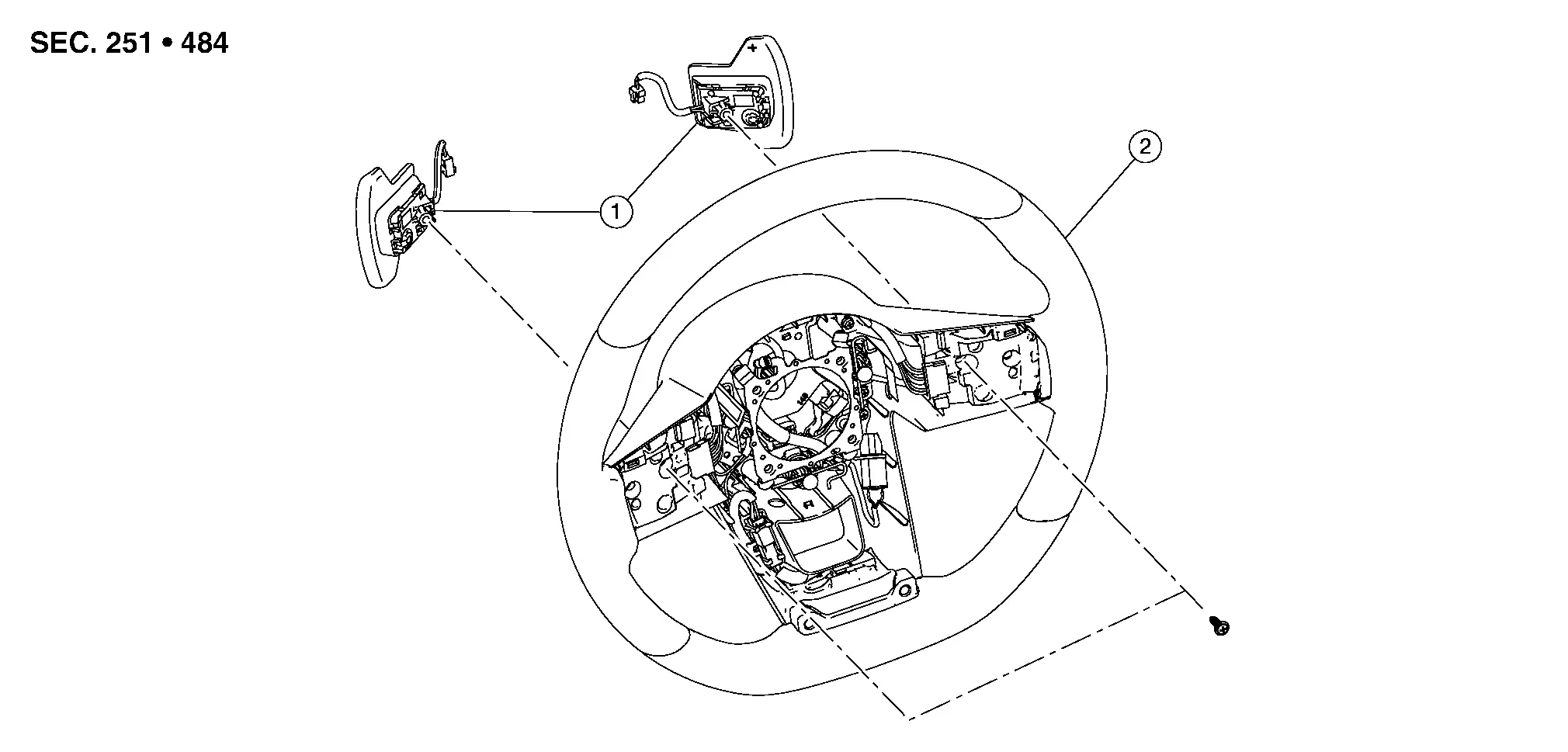
| 1. | Paddle shifter | 2. | Steering wheel |
Removal and Installation
REMOVAL
Remove ICC steering switch. Refer to Removal and Installation.
Remove screws from paddle shifters. Refer to Exploded View.
Disconnect harness connectors and remove paddle shifters.
INSTALLATION
Installation is in the reverse order of removal.
CAUTION:
Always perform ICC system action test to check that the ICC system operates normally after replacing the distance sensor or repairing any ICC system malfunction. Refer to Description.
Dog Clutch a Position Sensor Nissan Pathfinder 2022
Removal and Installation
REMOVAL
CAUTION:
When replacing dog clutch A position sensor, perform ADDITIONAL SERVICE WHEN REPLACING DOG CLUTCH A POSITION SENSOR". Refer to Description.
 NOTE:
NOTE:
When replacing dog clutch A position sensor, the harness assembly included with the service kit must be replaced.
Remove the control valve. Refer to Removal and Installation.
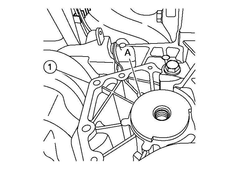
Remove the bolt securing the harness pass-thru.
Inside the transaxle, disconnect the dog clutch A position sensor harness and remove harness from transaxle.
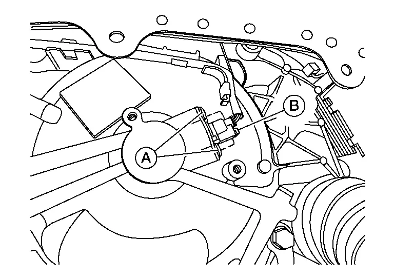
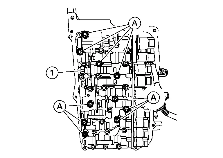
Remove bolts (A) and remove cover (1).
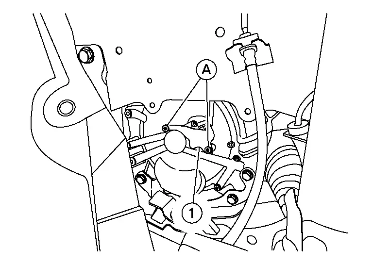
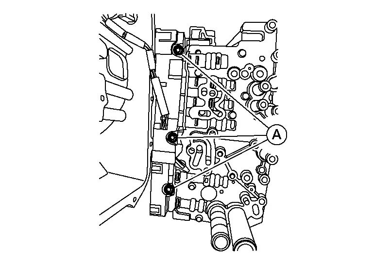
Remove bolts (A) and remove the dog clutch A position sensor (B).
INSTALLATION
 NOTE:
NOTE:
When replacing dog clutch A position sensor, the harness assembly included with the service kit must be replaced.
-
Install dog clutch A position sensor assembly (B) and tighten bolts (A).

Bolts (A) : 5.0 N·m (0.5 kg-m, 44 in-lb) -
Installation of remaining components are in the reverse order of removal.
CAUTION:
When replacing dog clutch A position sensor, perform ADDITIONAL SERVICE WHEN REPLACING DOG CLUTCH A POSITION SENSOR". Refer to Description.
Tcm Nissan Pathfinder SUV
Exploded View
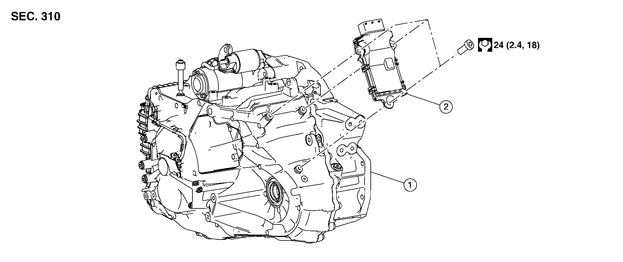
| 1. | Transaxle assembly | 2. | TCM |
Removal and Installation
CAUTION:
When replacing TCM, perform "ADDITIONAL SERVICE WHEN REPLACING TCM". Refer to Description.
REMOVAL
Remove the air cleaner and air duct. Refer to Removal and Installation.
Disconnect harness connector from TCM. Refer to Harness Connector (lever locking type).
CAUTION:
Make sure the Nissan Pathfinder vehicle cannot move with the parking brake applied.
Remove the TCM bolts and remove the TCM from the Nissan Pathfinder vehicle.
INSTALLATION
Installation is in the reverse order of removal.
CAUTION:
When replacing TCM, perform "ADDITIONAL SERVICE WHEN REPLACING TCM". Refer to Description.
Idle Stop Sensor Nissan Pathfinder
Removal and Installation
REMOVAL
Remove the front air cleaner and air duct. Refer to Removal and Installation.
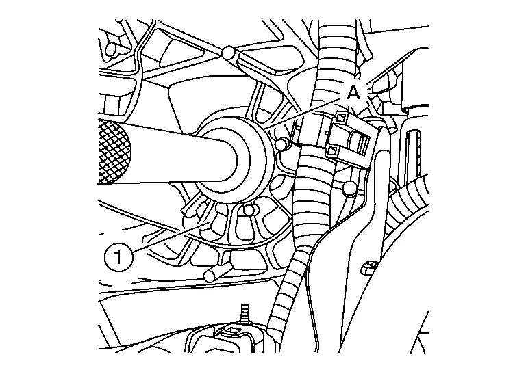
Remove bolt (A) and disconnect harness (B).
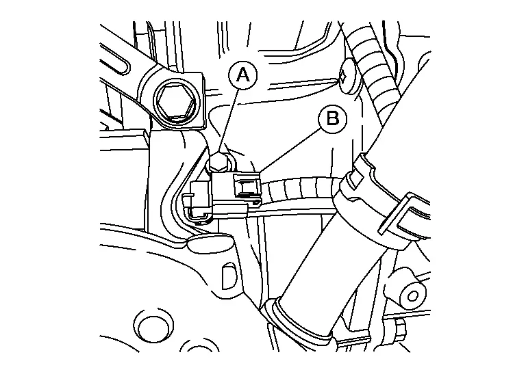
Remove idle stop sensor.
INSTALLATION
Installation is in the reverse order of removal.
Air Breather Hose Nissan Pathfinder
Removal and Installation
REMOVAL
Remove the front air duct. Refer to Exploded View.
Remove air breather hose.
INSTALLATION
Installation is in the reverse order of removal.
CAUTION:
-
Check that air breather hose is not collapsed or blocked due to folding or bending when installed.
-
Insert air breather hose (1) to air breather tube (2) all the way to the base of the tube.
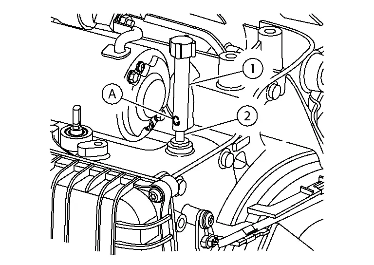
-
Insert air breather hose to air breather tube so that the paint mark (A) is facing forward.
Oil Pan ➤ Nissan Pathfinder
Control Valve Nissan Pathfinder R53
Exploded View
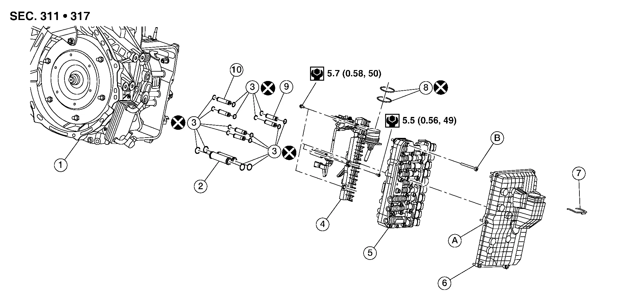
| 1. | Transaxle assembly | 2. | Connector tube | 3. | O-ring |
| 4. | Sensor assembly | 5. | Control valve | 6. | Oil pan |
| 7. | Clamp | 8. | O-ring | 9. | Adapter |
| 10. | Adapter | A. | Refer to Removal and Installation. | B. | Refer to Removal and Installation. |
Removal and Installation
CAUTION:
When replacing control valve, perform "ADDITIONAL SERVICE WHEN REPLACING CONTROL VALVE". Refer to Description.
REMOVAL
| Never Reuse These Parts | Part # Prefix | For additional information: |
|---|---|---|
| Hose clamp | 31088F | WATER HOSE EXPLODED VIEW |
| O-ring | — | CONTROL VALVE EXPLODED VIEW |
| Wheel hub lock nut | 40262 | FRONT WHEEL HUB EXPLODED VIEW |
| Nut | 40040B | FRONT WHEEL HUB EXPLODED VIEW |
| O-ring | 92471 | COOLER PIPE AND HOSE EXPLODED VIEW |
| Gasket | 20691 | EXHAUST SYSTEM EXPLODED VIEW |
| Seal bearing | 20695 | EXHAUST SYSTEM EXPLODED VIEW |
| Bolt | 20020B | EXHAUST SYSTEM EXPLODED VIEW |
| Nut | 20020A | EXHAUST SYSTEM EXPLODED VIEW |
| Bolt | 37010AA | REAR PROPELLER SHAFT EXPLODED VIEW |
| Nut | 37050B | REAR PROPELLER SHAFT EXPLODED VIEW |
| Nut | 54040B | FRONT COIL SPRING AND STRUT EXPLODED VIEW |
| Nut | 54060B | FRONT STABILIZER EXPLODED VIEW |
Remove oil pan. Refer to Removal and Installation.
Remove control valve bolts (A) and separate control valve assembly (1) from transaxle.
Remove bolts (A) from control valve and remove.
INSTALLATION
Installation is in the reverse order of removal.
CAUTION:
-
Do not reuse O-ring.
-
Completely clean the iron powder from the magnet area of oil pan and the magnets.
Install the oil pan to the transaxle case with the following procedure.
-
Install the control valve to the transaxle case, and then tighten the oil pan bolts to specification in sequence as shown.
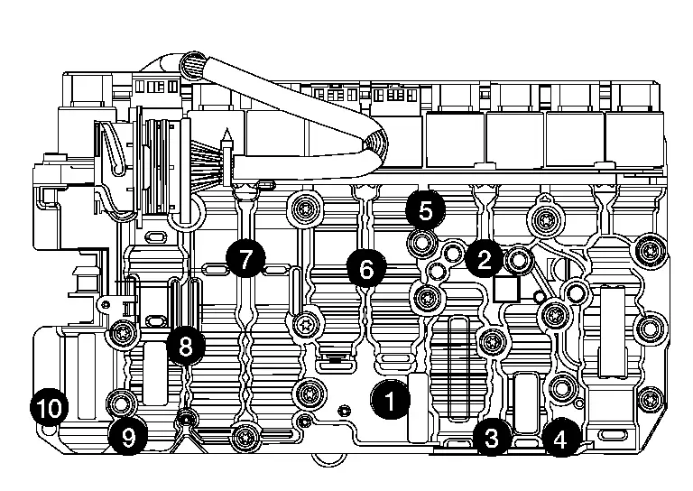
Control valve bolts : 8 N·m (0.8 kg-m, 71 in-lb)
CAUTION:
When replacing control valve, perform "ADDITIONAL SERVICE WHEN REPLACING CONTROL VALVE". Refer to Description.
Inspection and Adjustment
INSPECTION AFTER REMOVAL
-
Check oil pan for foreign material.
-
If a large amount of worn material is found, clutch plate may be worn.
-
If iron powder is found, bearings, gears, or clutch plates may be worn.
-
If aluminum powder is found, bushing may be worn, or chips or burrs of aluminum casting parts may enter.
-
Check points where wear is found in all cases.
INSPECTION AFTER INSTALLATION
Check the A/T fluid level and leakage. Refer to Inspection.
ADJUSTMENT AFTER INSTALLATION
Perform "ADDITIONAL SERVICE WHEN REPLACING CONTROL VALVE." Refer to Description.
A/t Sensor Unit Nissan Pathfinder 5th Gen
Removal and Installation
REMOVAL
CAUTION:
When replacing A/T sensor unit, perform "ADDITIONAL SERVICE WHEN REPLACING SENSOR UNIT". Refer to Description.
| Never Reuse These Parts | Part # Prefix | For additional information: |
|---|---|---|
| Hose clamp | 31088F | WATER HOSE EXPLODED VIEW |
| O-ring | — | CONTROL VALVE EXPLODED VIEW |
| Wheel hub lock nut | 40262 | FRONT WHEEL HUB EXPLODED VIEW |
| Nut | 40040B | FRONT WHEEL HUB EXPLODED VIEW |
Remove control valve. Refer to Removal and Installation.
Remove bolts (A) and remove harness assembly (1).
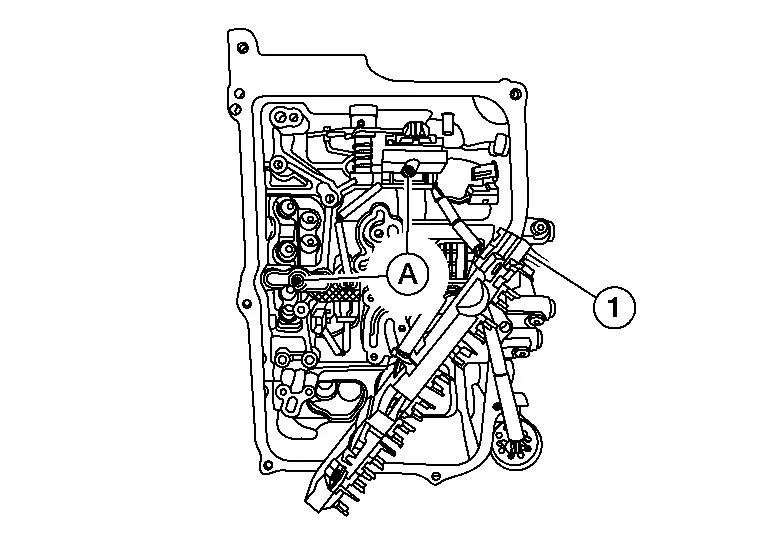
Remove sensor assembly.
INSTALLATION
Installation is in the reverse order of removal.
CAUTION:
When replacing A/T sensor unit, perform "ADDITIONAL SERVICE WHEN REPLACING SENSOR UNIT". Refer to Description.
Differential Side Oil Seal Nissan Pathfinder
Exploded View
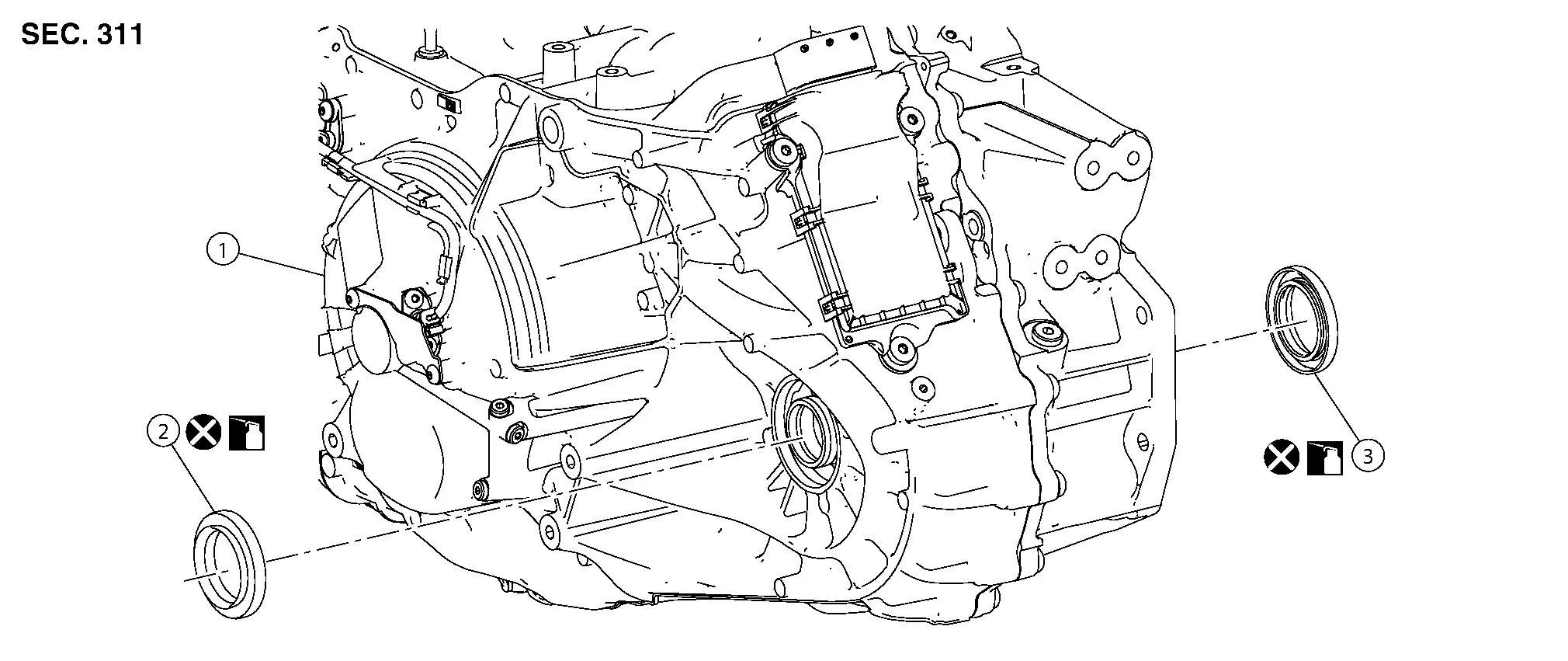
| 1. | Transaxle assembly | 2. | Differential side oil seal (left side) | 3. | Differential side oil seal (right side) (2WD models only) |
Removal and Installation (LH)
REMOVAL
| Never Reuse These Parts | Part # Prefix | For additional information: |
|---|---|---|
| Differential side oil seal | 38342P | DIFFERENTIAL SIDE OIL SEAL EXPLODED VIEW |
| Wheel hub lock nut | 40262 | FRONT WHEEL HUB EXPLODED VIEW |
| Nut | 40040B | FRONT WHEEL HUB EXPLODED VIEW |
Remove front drive shaft. Refer to Removal and Installation (LH).
Use oil seal remover or a similar means and remove the differential side oil seal.
CAUTION:
When removing the differential side oil seal, be careful not to scratch the oil seal mounting surfaces of the transaxle case and converter housing.
INSTALLATION
Install differential side oil seal (LH) using Tool (A) to transaxle assembly (1).
| Tool (A) | : — (NI-53124) |
Installation of remaining components are in the reverse order of removal.
Removal and Installation (RH)
REMOVAL
| Never Reuse These Parts | Part # Prefix | For additional information: |
|---|---|---|
| Differential side oil seal | 38342P | DIFFERENTIAL SIDE OIL SEAL EXPLODED VIEW |
| Wheel hub lock nut | 40262 | FRONT WHEEL HUB EXPLODED VIEW |
| Nut | 40040B | FRONT WHEEL HUB EXPLODED VIEW |
Remove front drive shaft. Refer to Removal and Installation (RH).
Use oil seal remover or a similar means and remove the differential side oil seal.
CAUTION:
When removing the differential side oil seal, be careful not to scratch the oil seal mounting surfaces of the transaxle case and converter housing.
INSTALLATION
Install differential side oil seal (RH) using Tool (A) to transaxle assembly (1).
| Tool (A) | : — (NI-53125) |
Installation of remaining components are in the reverse order of removal.
Inspection and Adjustment
INSPECTION AFTER INSTALLATION
Check for A/T fluid leakage. Refer to Inspection.
ADJUSTMENT AFTER INSTALLATION
Adjust A/T fluid level. Refer to Adjustment.
Water Hose Nissan Pathfinder 2022
Exploded View
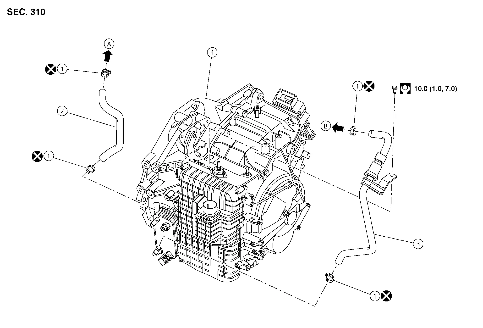
| 1. | Hose clamp | 2. | A/T water hose A | 3. | A/T water hose B |
| 4. | Transaxle assembly | A. | Water outlet | B. | Water outlet |
Removal and Installation
REMOVAL
WARNING:
Do not remove the radiator cap when the engine is hot. Serious burns could occur from high pressure engine coolant escaping from the radiator. Wrap a thick cloth around the cap. Slowly turn it a quarter turn to allow built-up pressure to escape. Carefully remove the cap by turning it all the way.
CAUTION:
Perform this step engine is cold.
 NOTE:
NOTE:
When removing components such as hoses, tubes/lines, etc., cap or plug openings to prevent fluid from spilling.
| Never Reuse These Parts | Part # Prefix | For additional information: |
|---|---|---|
| Hose clamp | 31088F | WATER HOSE EXPLODED VIEW |
Drain engine coolant. Refer to Draining.
Remove engine undercover (LH). Refer to Removal and Installation.
Remove hose clamp, and remove A/T water hose A from A/T fluid warmer.
CAUTION:
Do not reuse hose clamp.
Remove hose clamp, and remove A/T water hose B from A/T fluid warmer.
CAUTION:
Do not reuse hose clamp.
Remove air cleaner and air duct. Refer to Removal and Installation.
Remove hose clamp, and remove A/T water hose A.
CAUTION:
Do not reuse hose clamp.
Remove bolt from A/T water hose B.
Remove hose clamp, and remove A/T water hose B.
CAUTION:
Do not reuse hose clamp.
INSTALLATION
Installation is in the reverse order of removal.
CAUTION:
-
Do not reuse hose clamp.
-
Hose clamp should not interfere with the spool or bulge.
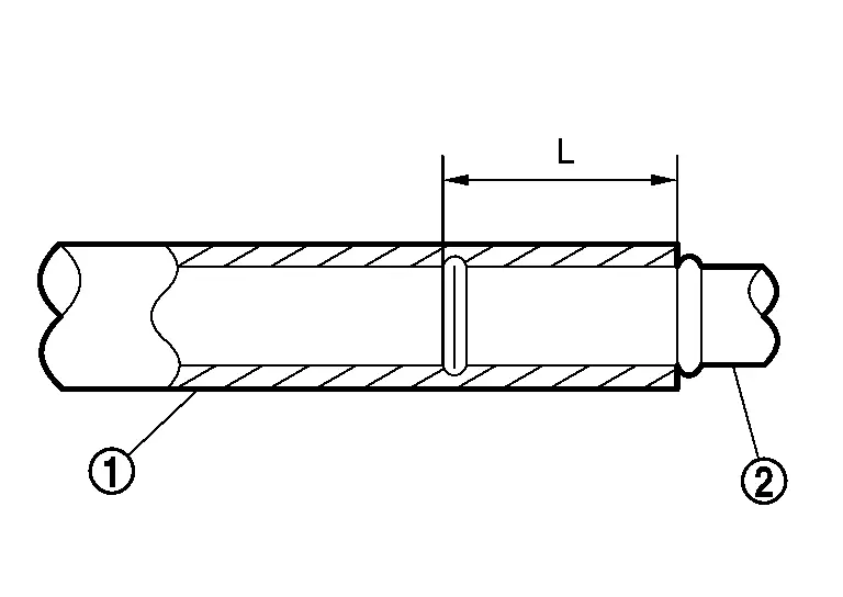
*Refer to the following when installing water hose.
| Water hose (1) | Installation side tube (2) | Direction of paint mark | Hose insertion depth |
|---|---|---|---|
| A/T water hose A | Water outlet | Upward | End reaches the 2-stage bulge. |
| A/T oil warmer | Frontward | ||
| A/T water hose B | A/T oil warmer | Frontward | |
| Water outlet | Upward |

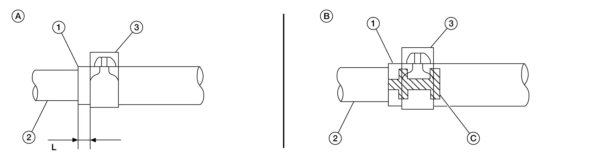
*Refer to the following when installing hose clamps.
| Water hose (1) | Installation side tube (2) | Hose clamp (3) | |
|---|---|---|---|
| Direction of tab | Clamping position* | ||
| Water hose A | Water outlet | Upward and 45° rightward | A: 5-7 mm (0.20 - 0.28 in) (L) from hose end. |
| A/T fluid warmer | Frontward | ||
| Water hose B | A/T fluid warmer | Forward and 45° downward | B: Align with the paint mark (C) as shown. |
| Water outlet | Downward | ||

Inspection
INSPECTION AFTER INSTALLATION
Start and warm up the engine. Visually check that there is no leakage of engine coolant and A/T fluid.
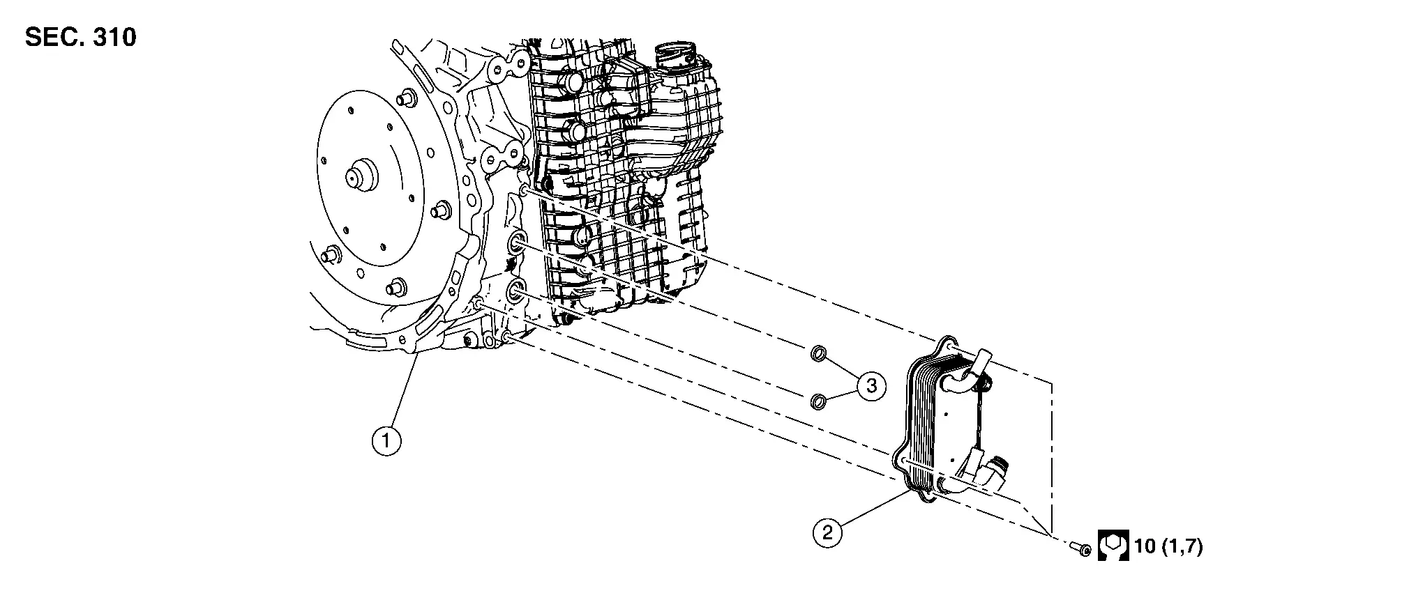
Fluid Cooler System Nissan Pathfinder Fifth generation
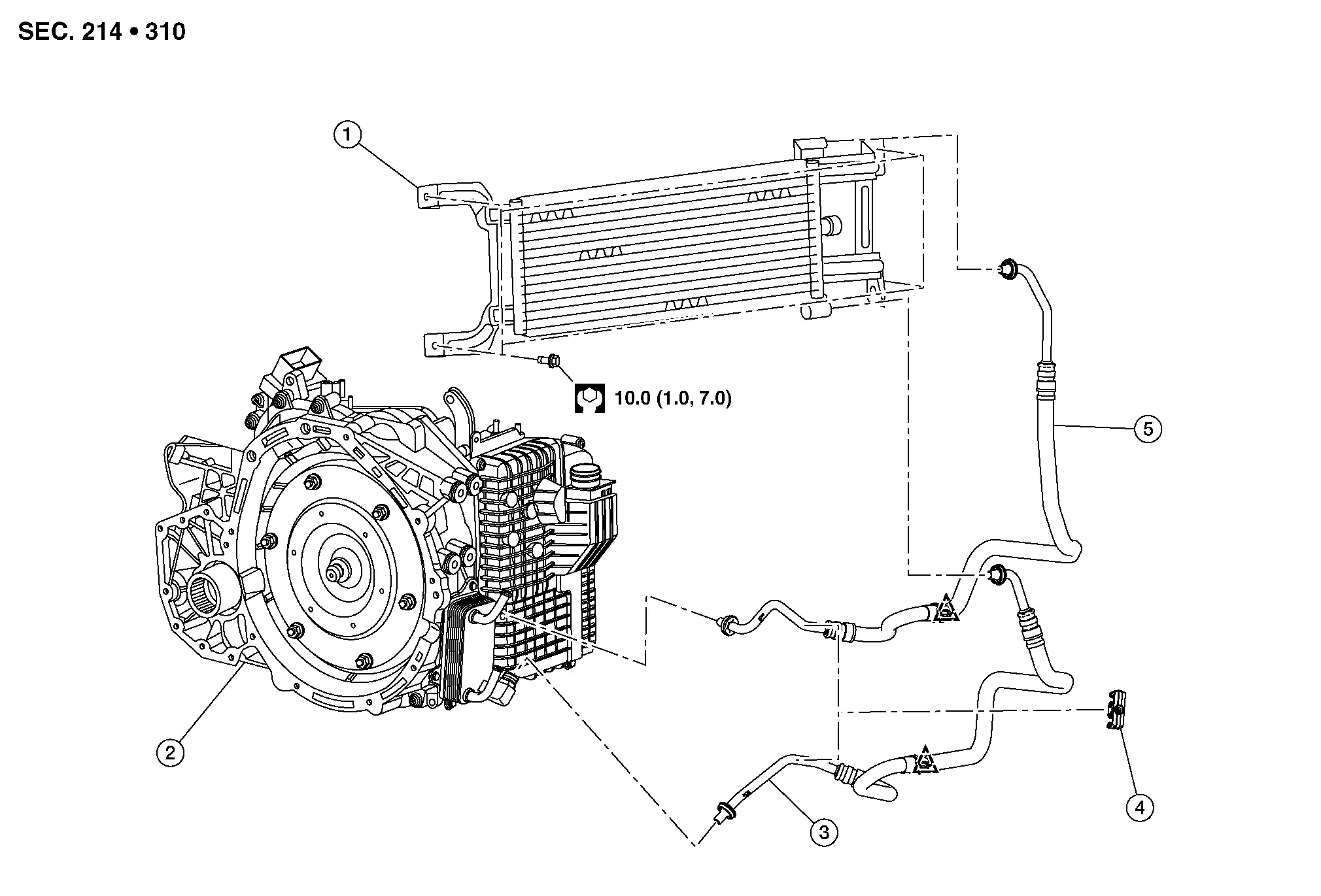
Exploded View
WITH TOW PACKAGE
 NOTE:
NOTE:
4WD shown, 2WD similar.
| 1. | A/T fluid cooler | 2. | Transaxle assembly | 3. | A/T fluid cooler hose A |
| 4. | Clamp | 5. | A/T fluid cooler hose B |
 |
Clip |
WITHOUT TOW PACKAGE
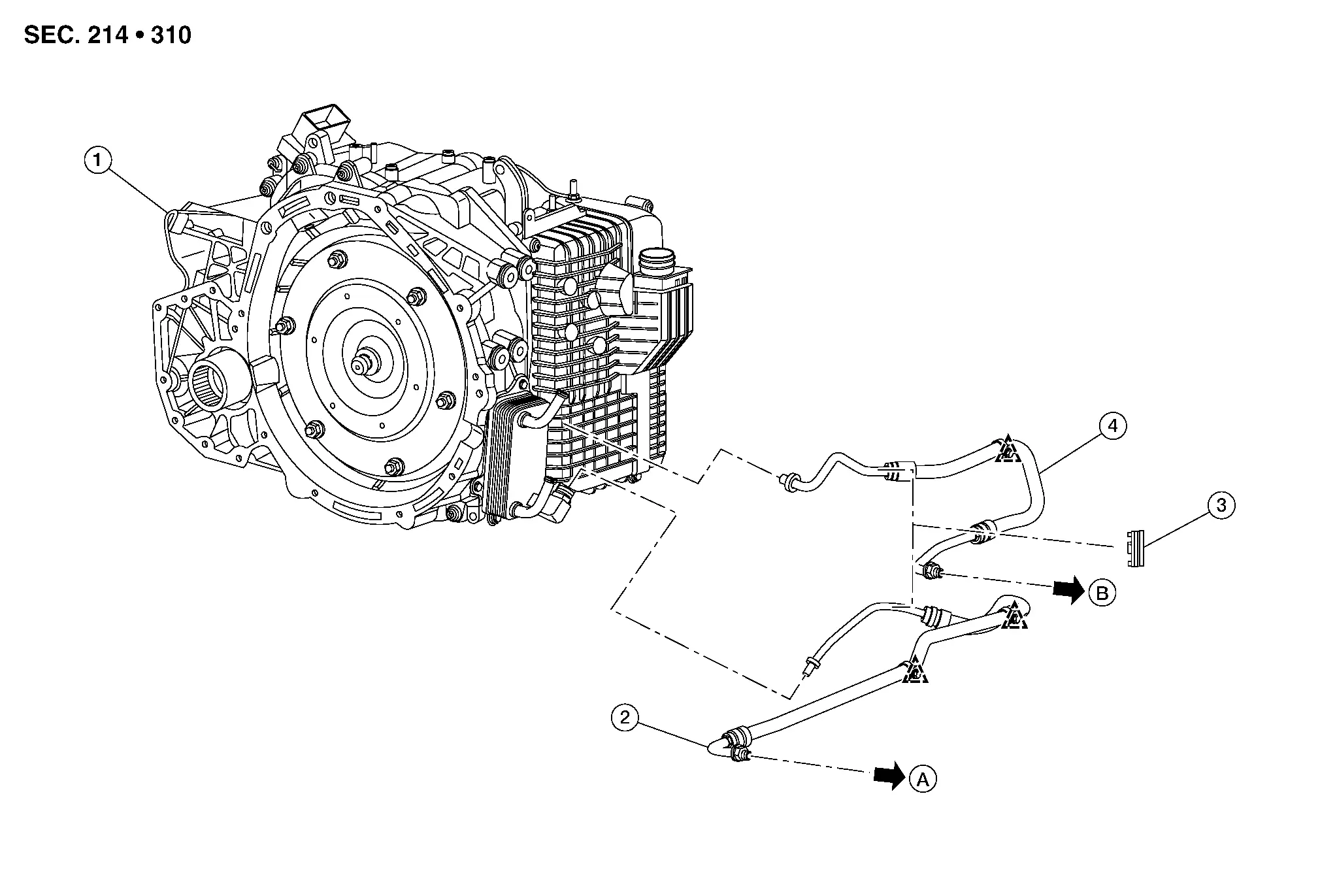
 NOTE:
NOTE:
4WD shown, 2WD similar.
| 1. | Transaxle assembly | 2. | A/T fluid cooler hose A | 3. | Clamp |
| 4. | A/T fluid cooler hose B |
 |
Clip | A. | To radiator. Refer to Exploded View. |
| B. | To radiator. Refer to Exploded View. |
Removal and Installation
WITH TOW PACKAGE
REMOVAL
 NOTE:
NOTE:
When removing components such as hoses, tubes/lines, etc., cap or plug openings to prevent fluid from spilling.
Remove front under cover (LH). Refer to Exploded View.
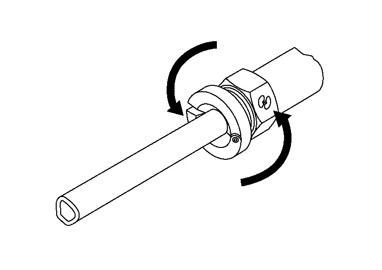
Remove the A/T fluid cooler hoses from the A/T fluid warmer using the following procedure:Remove the A/T fluid cooler hose cap (1) from the A/T fluid cooler hose (2).
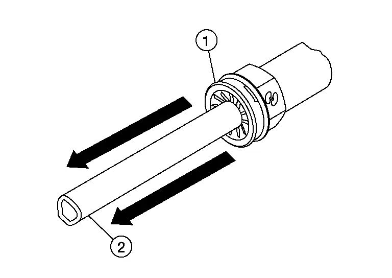
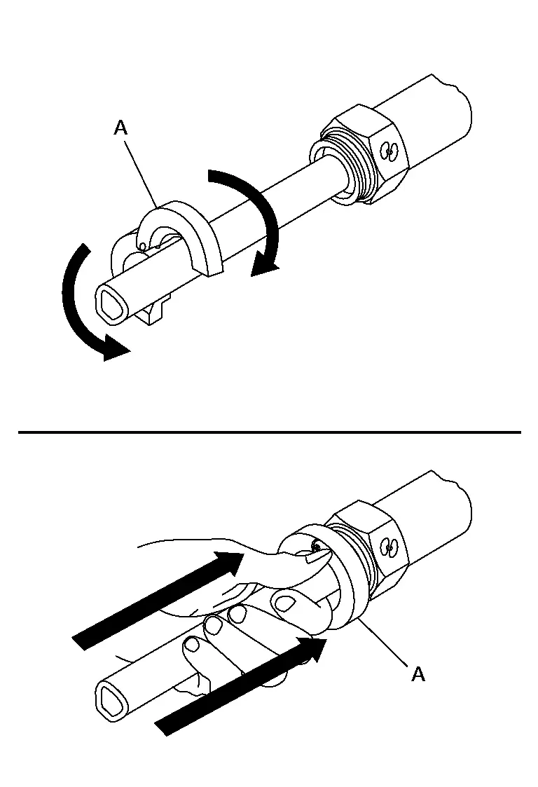

| (A) | : Suitable tool |
Using a suitable tool, release clip and separate A/T fluid cooler hose A from radiator core support.
Using a suitable tool, release clip and separate A/T fluid cooler hose B from radiator core support.
Remove front grille. Refer to Removal and Installation.
Disconnect harness connector from horn (HIGH).
Remove front bumper retainer. Refer to Exploded View.
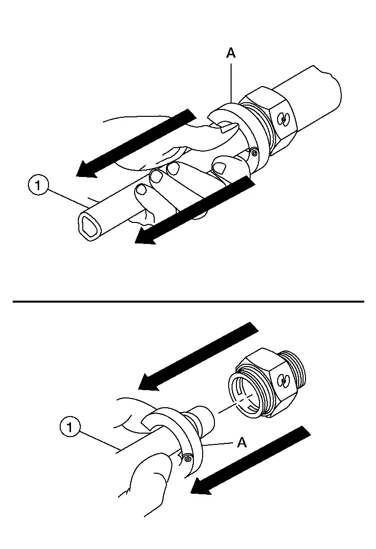
Remove the A/T fluid cooler tube from the A/T fluid cooler using the following procedure:Remove the A/T fluid cooler hose cap (1) from the A/T fluid cooler tube (2).


| (A) | : Suitable tool |
Remove bolts and remove A/T fluid cooler.
INSTALLATION
Installation is in the reverse order of removal.
WITHOUT TOW PACKAGE
REMOVAL
When removing components such as hoses, tubes/lines, etc., cap or plug openings to prevent fluid from spilling.
Remove front under cover (LH). Refer to Exploded View.
Remove the A/T fluid cooler hoses from the A/T fluid warmer using the following procedure:Remove the A/T fluid cooler hose cap (1) from the A/T fluid cooler hose (2).


| (A) | : Suitable tool |
Using a suitable tool, release clips and separate A/T fluid cooler hose A from radiator core support.
Using a suitable tool, release clip and separate A/T fluid cooler hose B from radiator core support.
Using a suitable tool, disconnect A/T fluid cooler hose A from radiator.
Using a suitable tool, disconnect A/T fluid cooler hose B from radiator.
INSTALLATION
Installation is in the reverse order of removal.
Inspection
INSPECTION AFTER INSTALLATION
Check for A/T fluid leakage. Refer to Inspection.
ADJUSTMENT AFTER INSTALLATION
Adjust A/T fluid level. Refer to Adjustment.
A/t Fluid Warmer Nissan Pathfinder
Exploded View
| 1. | Transaxle assembly | 2. | A/T fluid warmer | 3. | Seal |
Removal and Installation
REMOVAL
WARNING:
Do not remove the radiator cap when the engine is hot. Serious burns could occur from high pressure coolant escaping from the radiator. Wrap a thick cloth around the cap. Slowly turn it a quarter turn to allow built-up pressure to escape. Carefully remove the cap by turning it all the way.
CAUTION:
Perform this step engine is cold.
 NOTE:
NOTE:
When removing components such as hoses, tubes/lines, etc., cap or plug openings to prevent fluid from spilling.
| Never Reuse These Parts | Part # Prefix | For additional information: |
|---|---|---|
| Hose clamp | 31088F | WATER HOSE EXPLODED VIEW |
Drain engine coolant. Refer to Draining.
Remove the front under cover (RH/LH). Refer to Removal and Installation.
Remove hose clamp, and remove A/T water hose A from A/T fluid warmer.
CAUTION:
Do not reuse hose clamp.
Remove hose clamp, and remove A/T water hose B from A/T fluid warmer.
CAUTION:
Do not reuse hose clamp.
Remove A/T fluid cooler hose A from A/T fluid warmer.
Remove A/T fluid cooler hose B from A/T fluid warmer.
Remove A/T fluid warmer bolts and remove A/T fluid warmer.
CAUTION:
Do not reuse O-rings.
INSTALLATION
Installation is in the reverse order of removal.
CAUTION:
-
Do not reuse hose clamp or O-rings.
-
Hose clamp should not interfere with the spool or bulge.
*Refer to the following when installing water hose.
| Water hose (1) | Installation side tube (2) | Direction of paint mark | Hose insertion depth |
|---|---|---|---|
| A/T water hose A | A/T fluid warmer | Frontward | End reaches the 2-stage bulge. |
| A/T water hose B | A/T fluid warmer | Frontward |
*Refer to the following when installing hose clamps.
| Water hose (1) | Installation side tube (2) | Hose clamp (3) | |
|---|---|---|---|
| Direction of tab | Clamping position* | ||
| Water hose A | A/T fluid warmer | Frontward | A: 5-7 mm (0.20 - 0.28 in) (L) from hose end. |
| Water hose B | A/T fluid warmer | Forward and 45° downward | B: Align with the paint mark (C) as shown. |
Inspection
INSPECTION AFTER INSTALLATION
-
Check for A/T fluid leakage. Refer to Inspection.
-
Start and warm up the engine. Visually check that there is no leakage of engine coolant and A/T fluid.
ADJUSTMENT AFTER INSTALLATION
Adjust A/T fluid level. Refer to Adjustment.
Plug Nissan Pathfinder SUV
Exploded View
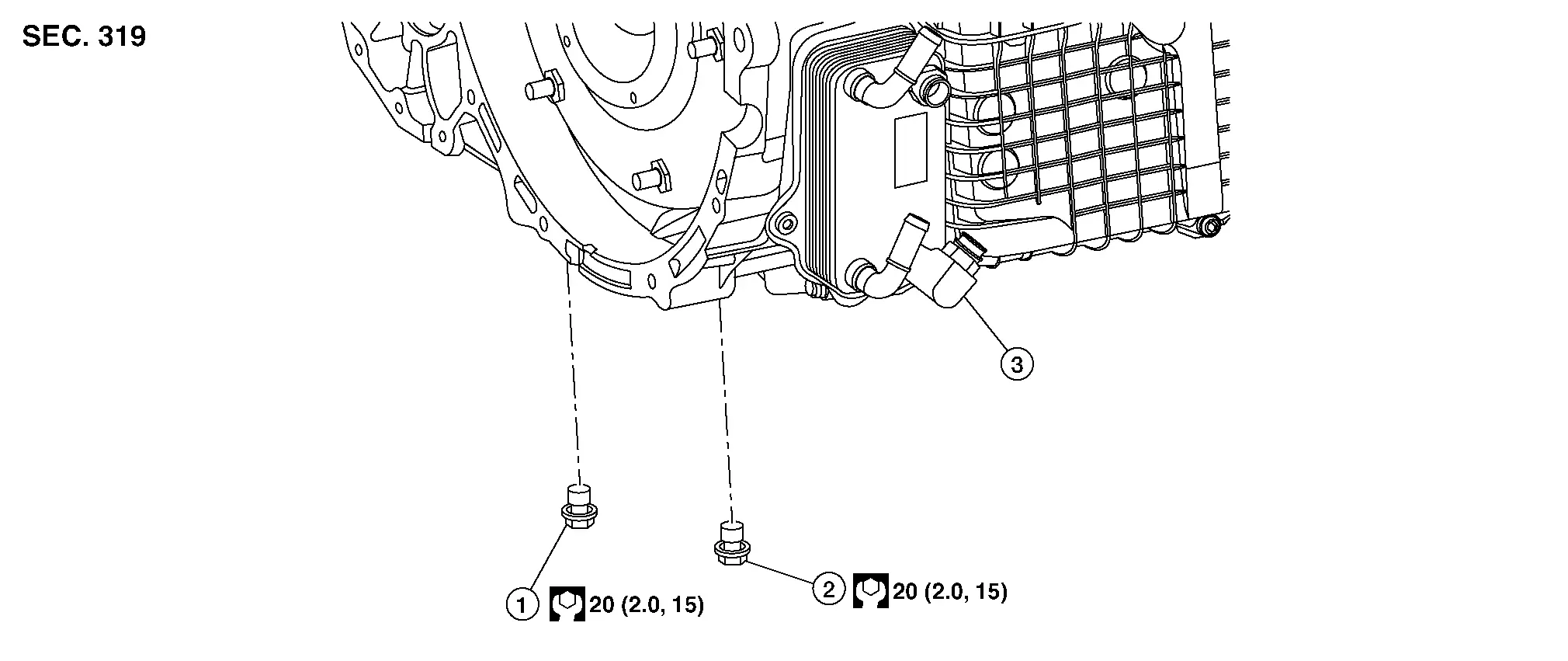
| 1. | Filler plug | 2. | Drain plug | 3. | Transaxle assembly |
Removal and Installation
REMOVAL
Remove the plugs.
INSTALLATION
Installation is in the reverse order of removal.
Inspection
INSPECTION AFTER INSTALLATION
Check for A/T fluid leakage. Refer to Inspection.
Adjustment
ADJUSTMENT AFTER INSTALLATION
Adjust A/T fluid level. Refer to Adjustment.

Nissan Pathfinder (R53) 2022-2026 Service Manual
Removal and Installation
- Electric Shift Selector
- Electric Shift Control Module
- Paddle Shifter
- Dog Clutch a Position Sensor
- Tcm
- Idle Stop Sensor
- Air Breather Hose
- Oil Pan ➤
- Control Valve
- A/t Sensor Unit
- Differential Side Oil Seal
- Water Hose
- Fluid Cooler System
- A/t Fluid Warmer
- Plug
Contact Us
Nissan Pathfinder Info Center
Email: info@nipathfinder.com
Phone: +1 (800) 123-4567
Address: 123 Pathfinder Blvd, Nashville, TN 37214, USA
Working Hours: Mon–Fri, 9:00 AM – 5:00 PM (EST)
