Nissan Pathfinder: Transaxle & Transmission - 9at: Ge9f01a
- Precautions ➤
- Preparation
- Symptom Diagnosis. System Symptom
- Periodic Maintenance. A/t Fluid
- Unit Removal and Installation. Transaxle Assembly ➤
- Unit Disassembly and Assembly. Torque Converter and Converter Housing Oil Seal
- Service Data and Specifications (SDS)
Precautions ➤ Nissan Pathfinder 2022
Preparation Nissan Pathfinder SUV
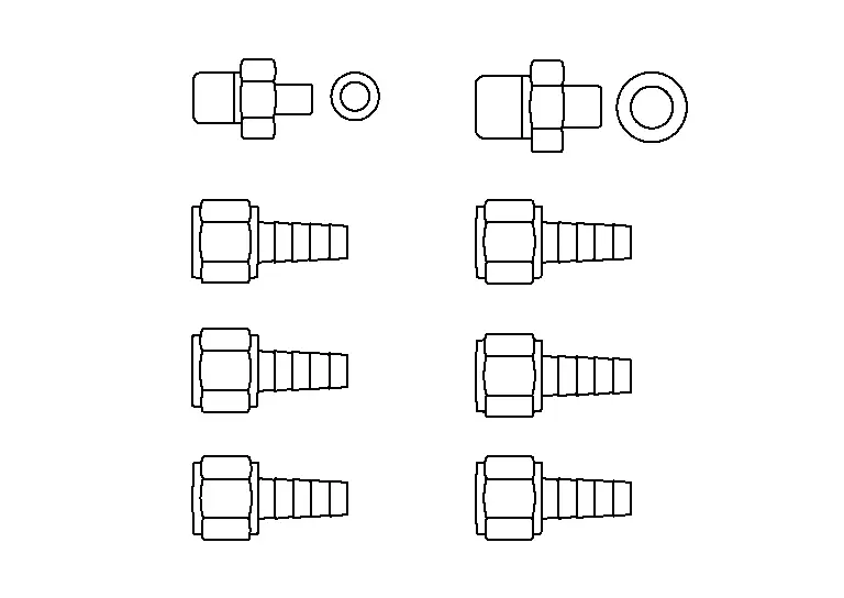
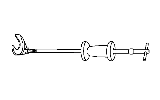
Special Service Tools
The actual shape of the tools may differ from those illustrated here.
|
Tool number (TechMate No.) Tool name | Description | |
|---|---|---|
|
|
A/T fluid changing and adjustment |
|
( — ) (NI-52584) A/T stand pipe adapter kit |
|
A/T fluid changing and adjustment |
|
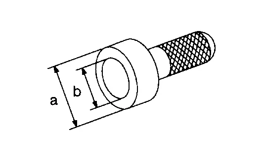
KV38107900 (NI-52469–1) Differential side oil seal protector |
|
Installing drive shaft A: 32 mm (1.26 in) dia B: Minimum 23 mm (0.91 in) |
|
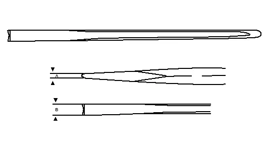
— (NI-52982) Lock nut chisel (Cape chisel) |
|
Removing wheel hub lock nut |
|
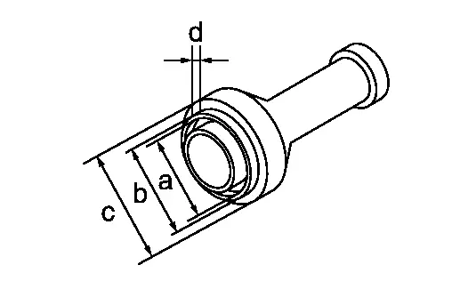
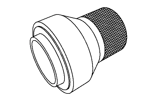
KV31103700 ( — ) Drift |
|
Differential side oil seal (Transaxle case side) a: 53 mm (2.09 in) dia. b: 57 mm (2.24 in) dia. c: 70 mm (2.76 in) dia. d: 8 mm (0.31 in) dia. |
|
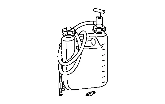
(NI-51001) Transmission fill pump |
|
Oil fill kit |
|
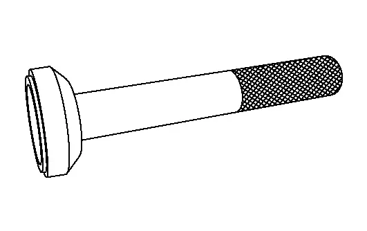
— (NI-53124) Output seal installer |
|
Installing differential side oil seal (LH) |
|
— (NI-53125) Output seal installer |
|
Installing differential side oil seal (RH) |
|
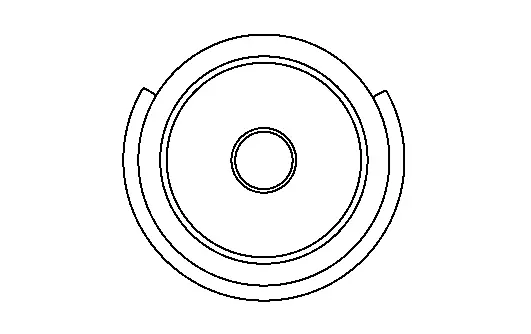
— (NI-53126) Input seal installer |
|
Installing converter housing oil seal |
*: The O-ring as a unit part is set as a SST.
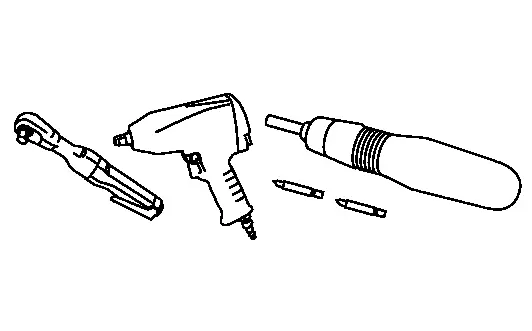
Commercial Service Tools
| Tool name | Description | |
|---|---|---|
| Power tool |
|
Loosening nuts, screws and bolts |
| Drift |
|
Installing differential side oil seal (Converter housing side) a: 47mm (1.85 in) dia. b: 51 mm (2.01 in) dia. c: 70 mm (2.76 in) dia. d: 8 mm (0.31 in) dia. |
| Drift |
|
Installing converter housing oil seal a: 65 mm (2.56 in) dia. b: 60 mm (2.36 in) dia. |
| Lock nut crimp punch (Cold chisel) |
|
Installing wheel hub lock nut a: 5 mm (0.20 in) b: 7 mm (0.28 in) |
| Drive shaft joint puller |
|
Removing drive shaft |
| 5/8" Disconnect tool |
|
For removal of the A/T fluid cooler hoses. |

Always Replace with New Parts
| Never Reuse These Parts | Part # Prefix | For additional information: |
|---|---|---|
| Hose clamp | 31088F | WATER HOSE EXPLODED VIEW |
| Differential side oil seal | 38342P | WATER OUTLET AND WATER PIPING EXPLODED VIEW |
| Converter housing oil seal | 31110 | TORQUE CONVERTER AND CONVERTER HOUSING OIL SEAL EXPLODED VIEW |
| O-ring | — | CONTROL VALVE EXPLODED VIEW |
| Wheel hub lock nut | 40262 | FRONT WHEEL HUB EXPLODED VIEW |
| Nut | 40040B | FRONT WHEEL HUB EXPLODED VIEW |
| O-ring | 92471 | COOLER PIPE AND HOSE EXPLODED VIEW |
| Gasket | 20691 | EXHAUST SYSTEM EXPLODED VIEW |
| Seal bearing | 20695 | EXHAUST SYSTEM EXPLODED VIEW |
| Bolt | 20020B | EXHAUST SYSTEM EXPLODED VIEW |
| Nut | 20020A | EXHAUST SYSTEM EXPLODED VIEW |
| Bolt | 37010AA | REAR PROPELLER SHAFT EXPLODED VIEW |
| Nut | 37050B | REAR PROPELLER SHAFT EXPLODED VIEW |
| Nut | 54040B | FRONT COIL SPRING AND STRUT EXPLODED VIEW |
| Nut | 54060B | FRONT STABILIZER EXPLODED VIEW |
| Bolt | 14002B | EXHAUST MANIFOLD AND THREE WAY CATALYST EXPLODED VIEW |
| Gasket | 14036M | EXHAUST MANIFOLD AND THREE WAY CATALYST EXPLODED VIEW |
Symptom Diagnosis. System Symptom Nissan Pathfinder SUV
Symptom Table
The diagnostics item numbers show the sequence for inspection. Inspect in order from item 1.
| Diagnostic item | Reference | Symptom | |||||||||||||||||
|---|---|---|---|---|---|---|---|---|---|---|---|---|---|---|---|---|---|---|---|
| Poor performance | Function trouble | ||||||||||||||||||
| Driving performance | Strange noise | Gear does no change | Poor shifting | Poor power transmission | |||||||||||||||
| Shift point is high in “D” position. | Shift point is low in “D” position. | Large shock | Judder | Slip | Slip | ||||||||||||||
| When shifting gears | |||||||||||||||||||
| →“D” position | →“R” position | Downshift when accelerator pedal is depressed | Upshift when accelerator pedal is released | Lock-up | In “R” position | In “N” position | In “D” position | Engine at idle | In “D” position | In “M” position | When shifting gears | With selector lever in “D” position, acceleration is extremely poor. | With selector lever in “R” position, acceleration is extremely poor. | No creep at all. | Extremely large creep. | ||||
| Nissan Pathfinder Vehicle speed signal | Diagnosis Procedure | 2 | 2 | 2 | 2 | 1 | 1 | 1 | 1 | 2 | 1 | 1 | 1 | 1 | 2 | 3 | 3 | 3 | 3 |
| Accelerator pedal position signal | DTC Index | 1 | 1 | 2 | 2 | 1 | 1 | 2 | 2 | 2 | 2 | 2 | 1 | 1 | 1 | 2 | 2 | 2 | 2 |
| Engine speed signal | DTC Index | 1 | 1 | 1 | 1 | 1 | 1 | 1 | 1 | 1 | 1 | 1 | 1 | 1 | 1 | 1 | 1 | 1 | 1 |
| Battery voltage | Diagnosis Procedure | 3 | 3 | 3 | 3 | ||||||||||||||
| Electric shift selector | DTC Index | 1 | 1 | 1 | 1 | 2 | 3 | 3 | 3 | 3 | 1 | 1 | 1 | 1 | 1 | 1 | |||
| Paddle shifters | Diagnosis Procedure | 1 | 1 | 1 | 1 | 3 | 3 | 3 | 3 | 3 | 1 | 1 | 3 | ||||||
| Stop lamp switch | Diagnosis Procedure | 1 | 1 | 1 | 1 | 1 | 1 | 2 | 2 | 2 | 2 | 2 | 1 | 1 | 1 | 1 | 1 | 1 | 1 |
| CAN communication | Trouble Diagnosis Flow Chart | 1 | 1 | 1 | 1 | 1 | 1 | 1 | 1 | 1 | 1 | 1 | 1 | 1 | 1 | 1 | 1 | 1 | 1 |
| TCM | Removal and Installation | 2 | 2 | 2 | 2 | 2 | 2 | 2 | 3 | 3 | 3 | 3 | 1 | 1 | 1 | 1 | 1 | ||
|
|
1 | 1 | 1 | 1 | 1 | 1 | 1 | 1 | 1 | 1 | 1 | 1 | 1 | 1 | 1 | 1 | 1 | 1 |
| Control valve (Each pressure regulator, parking lock valve, parking lock actuator) | Removal and Installation | 1 | 1 | 1 | 1 | 1 | 1 | 1 | 1 | 1 | 1 | 1 | 1 | 1 | 1 | 1 | 1 | 1 | 1 |
| Transaxle assembly (Dog clutch F position sensor, Oil pump, Each clutch/brake, Planetary gear, Parking component) | Removal and Installation | 3 | 3 | 3 | 3 | 3 | 3 | 3 | 3 | 3 | 3 | 3 | 2 | 2 | 3 | 3 | 3 | 3 | 3 |
| Torque converter | Disassembly | 3 | 3 | 3 | 3 | 3 | 3 | 3 | 3 | 3 | 3 | 3 | 2 | 2 | 3 | 3 | 3 | 3 | 3 |
| Insufficient shift control learning | Refer to following. | 3 | 3 | 1 | 1 | 1 | 1 | 1 | 2 | 2 | 1 | 3 | 3 | 3 | 3 | ||||
Shifting control learning
This transmission learns to achieve optimum shifting by repeatedly shifting gears up and down while driving.
When a shift shock or lag occurs during driving, the following driving is performed to make the transmission learn shift control.
-
Reproduce the phenomenon complained by the customer.
-
The same conditions as the complaint phenomenon (gear position / engine speed / accelerator opening angle) are repeated about 10 times.
Periodic Maintenance. A/t Fluid Nissan Pathfinder R53
Inspection
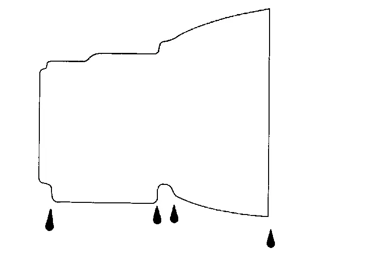
FLUID LEAKAGE
-
Check transaxle surrounding area (oil seal and plug etc.) for fluid leakage.
-
If anything is found, repair or replace damaged parts and adjust A/T fluid level. Refer to Adjustment.
Replacement
| A/T fluid | : Refer to General Specification. |
| Fluid capacity | : Refer to General Specification. |
CAUTION:
-
Always use shop paper. Never use shop cloth.
-
Use caution when looking into the drain hole as there is a risk of dripping fluid entering the eye.
-
After replacement, always perform A/T fluid leak check.
Select “Data Monitor” in “TRANSMISSION” using CONSULT.
Select “FLUID TEMP” and confirm that the A/T fluid temperature is between 35°C and 45°C (95°F to 113°F).
Check that the selector lever is in the “P” position, then completely engage the parking brake.
Lift up the Nissan Pathfinder vehicle.
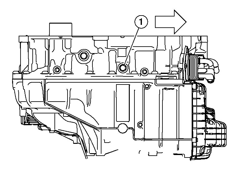
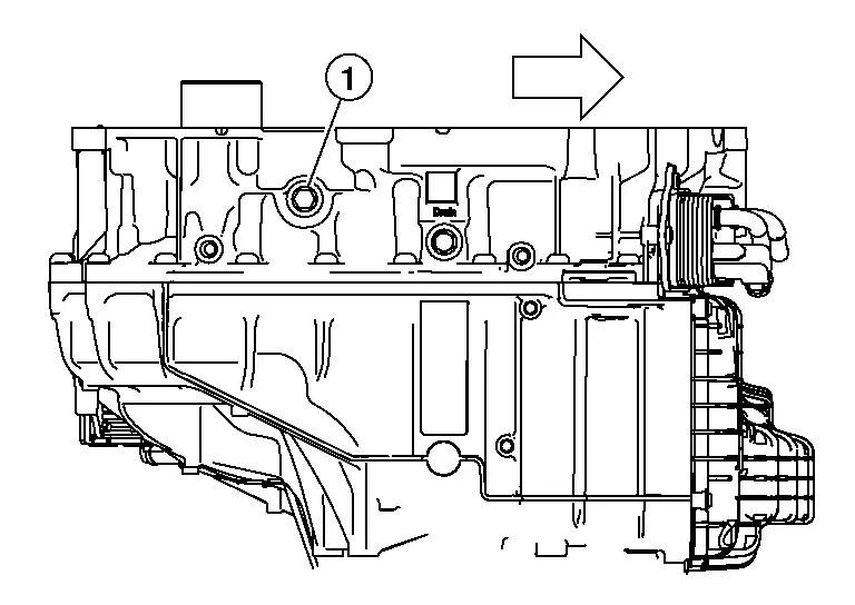
Remove the drain plug (1) and drain the A/T fluid from A/T case.
 |
: Nissan Pathfinder Vehicle front |
Install the drain plug to specified torque. Refer to Exploded View.
Remove the fill plug (1).

 |
: Nissan Pathfinder Vehicle front |
Install the charging pipe set (A/T stand pipe adapter kit) KV311039S0 (NI-52584) into the overflow plug hole.
CAUTION:
Tighten the charging pipe by hand.
Install the ATF changer hose to the charging pipe.
CAUTION:
Press the ATF changer hose all the way onto the charging pipe until it stops.
Fill approximately 7 liter (7-1/2 US qt, 6-1/4 lmp qt) of the A/T fluid.
Remove the ATF changer hose and charging pipe, then install and finger tighten the fill plug.
 NOTE:
NOTE:
Perform this work quickly because A/T fluid leaks.
Start the engine.
Park the Nissan Pathfinder vehicle on a level surface with the engine running and parking brake set.
Using CONSULT-III plus, ensure that the A/T fluid temperature is between 95°F to 113°F (35°C to 45°C).
With Nissan Pathfinder vehicle in PARK and A/T fluid temperature in correct range, let engine run at 2000 rpm for about 10 seconds.
Shift the transmission into REVERSE for 10 seconds.
Shift the transmission into DRIVE for 10 seconds.
Shift the transmission into 1st for 10 seconds.
Shift the transmission into 2nd for 10 seconds.
Shift the transmission into 3rd for 10 seconds.
Shift the transmission into 4th for 10 seconds.
CAUTION:
Do not exceed 4th gear or transmission damage can occur.
Shift the transmission into NEUTRAL until wheels come to a complete stop.
Shift the transmission into PARK.
Lift up the Nissan Pathfinder vehicle.
Remove the fill plug (1).

 |
: Nissan Pathfinder Vehicle front |
If A/T fluid flows out of fill hole, let A/T fluid flow out until flow is reduced to a thin stream and then install fill plug and tighten to specification. If A/T fluid does not run out of fill hole repeat steps 1–18 adding small quantities of A/T fluid at a time.
Adjustment
| A/T fluid | : Refer to General Specification. |
| Fluid capacity | : Refer to General Specification. |
CAUTION:
-
During adjustment of the A/T fluid level, check CONSULT so that the oil temperature may be maintained from 35°C to 45°C (95°F to 113°F)
-
Use caution when looking into the drain hole as there is a risk of dripping fluid entering the eye.
-
After replacement, always perform A/T fluid leak check.
Remove the fill plug (1).

 |
: Nissan Pathfinder Vehicle front |
Install the charging pipe set (A/T stand pipe adapter kit) KV311039S0 (NI-52584) into the overflow plug hole.
CAUTION:
Tighten the charging pipe by hand.
Install the ATF changer hose to the charging pipe.
CAUTION:
Press the ATF changer hose all the way onto the charging pipe until it stops.
Fill A/T with small amount of the A/T fluid.
Remove the ATF changer hose and charging pipe, then install and finger tighten the fill plug.
 NOTE:
NOTE:
Perform this work quickly because A/T fluid leaks.
Start the engine.
Park the Nissan Pathfinder vehicle on a level surface with the engine running and parking brake set.
Using CONSULT-III plus, ensure that the A/T fluid temperature is between 95°F to 113°F (35°C to 45°C).
With Nissan Pathfinder vehicle in PARK and A/T fluid temperature in correct range, let engine run at 2000 rpm for about 10 seconds.
Shift the transmission into REVERSE for 10 seconds.
Shift the transmission into DRIVE for 10 seconds.
Shift the transmission into 1st for 10 seconds.
Shift the transmission into 2nd for 10 seconds.
Shift the transmission into 3rd for 10 seconds.
Shift the transmission into 4th for 10 seconds.
CAUTION:
Do not exceed 4th gear or transmission damage can occur.
Shift the transmission into NEUTRAL until wheels come to a complete stop.
Shift the transmission into PARK.
Lift up the Nissan Pathfinder vehicle.
Remove the fill plug (1).
 |
: Nissan Pathfinder Vehicle front |
If A/T fluid flows out of fill hole, let A/T fluid flow out until flow is reduced to a thin stream and then install fill plug and tighten to specification. If A/T fluid does not run out of fill hole repeat steps 1–18 adding small quantities of A/T fluid at a time.
Unit Removal and Installation. Transaxle Assembly ➤ Nissan Pathfinder 5th Gen
Unit Disassembly and Assembly. Torque Converter and Converter Housing Oil Seal Nissan Pathfinder Fifth generation
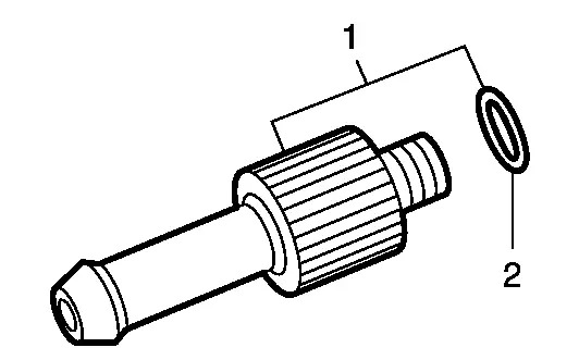
Exploded View
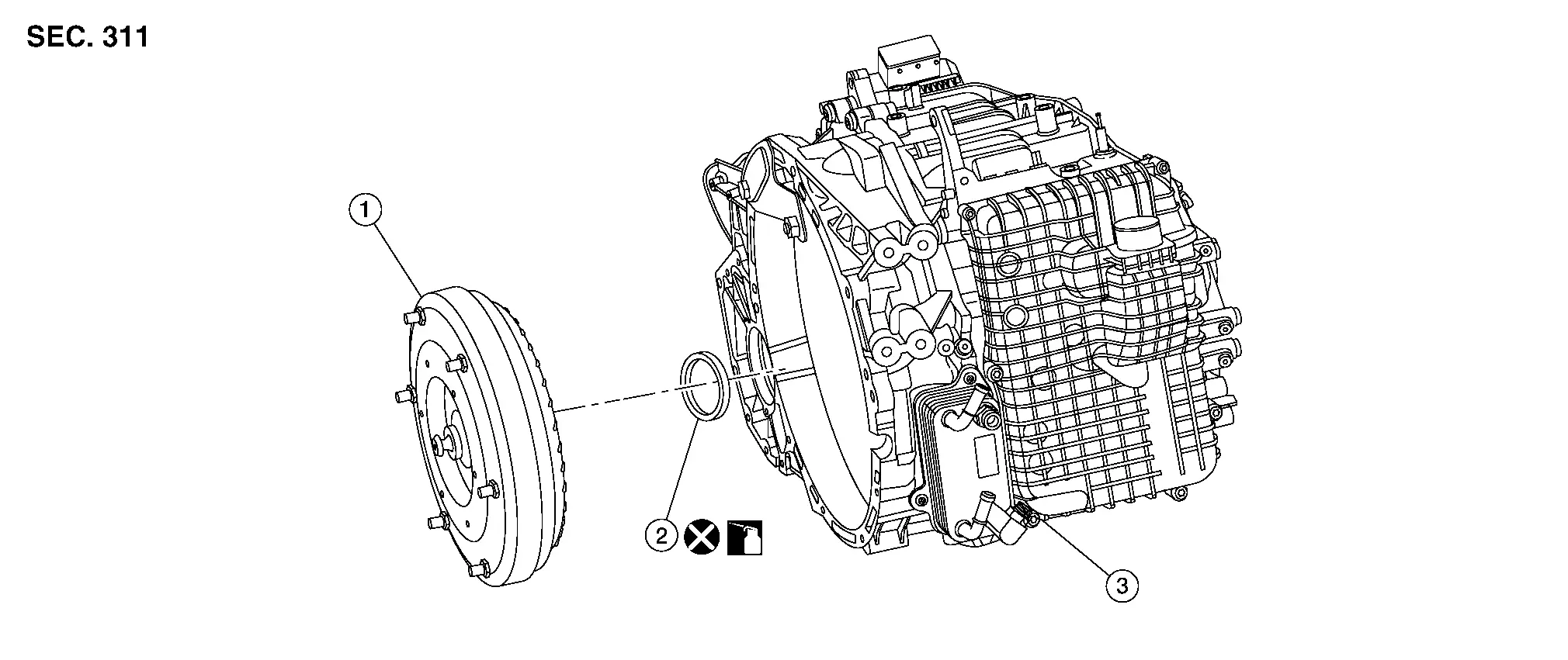
| 1. | Torque converter | 2. | Converter housing oil seal | 3. | Transaxle assembly |
Disassembly
| Never Reuse These Parts | Part # Prefix | For additional information: |
|---|---|---|
| Converter housing oil seal | 31110 | Exploded View |
Remove transaxle assembly. Refer to Removal and Installation.
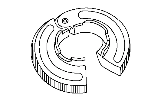
Remove torque converter from transaxle assembly.
CAUTION:
Do not damage the bushing on the inside of torque converter sleeve when removing torque converter.
Remove converter housing oil seal using suitable tool.
CAUTION:
Be careful not to scratch converter housing.
Assembly
Assembly is in the reverse order of disassembly.
CAUTION:
Do not reuse converter housing oil seal.
 NOTE:
NOTE:
Lubricate converter housing oil seal prior to installation.
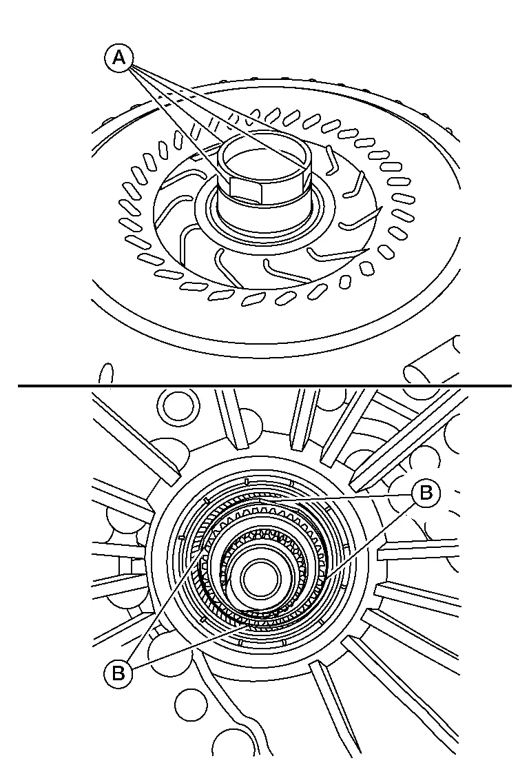
-
Drive converter housing oil seal (1) evenly using Tool (A) until converter housing oil seal is flush with transaxle assembly (2).
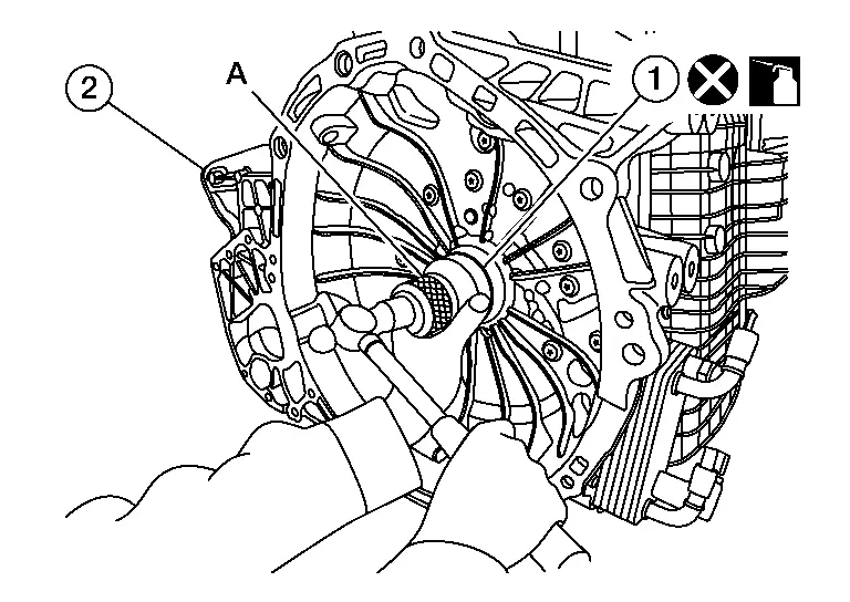
Tool (A) : — (J-53126) Unit: mm (in)
Dimension (B) 1.0 ± 0.5 (0.039 ± 0.020) 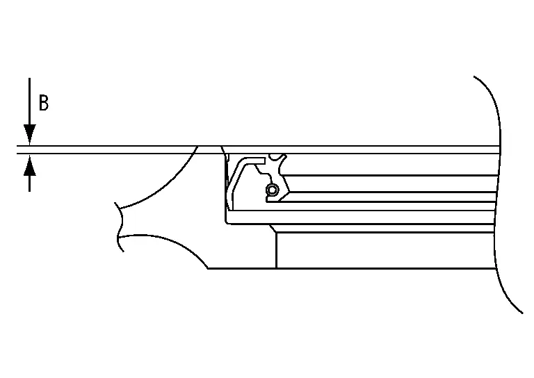
 NOTE:
NOTE:
Converter housing oil seal pulling direction is used as the reference.
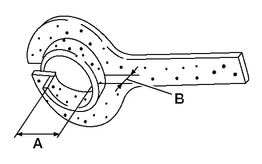
-
Align grooves (A) of the torque converter to the drive sprocket hole gooves (B) on the transaxle assembly side.
CAUTION:
-
Rotate the torque converter for installing torque converter.
-
Do not damage the bushing inside the torque converter sleeve when installing the converter housing oil seal.
-
Inspection
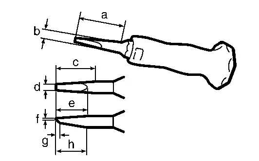
INSPECTION AFTER INSTALLATION
-
After inserting torque converter to the A/T, check dimension (A) within the reference value limit.
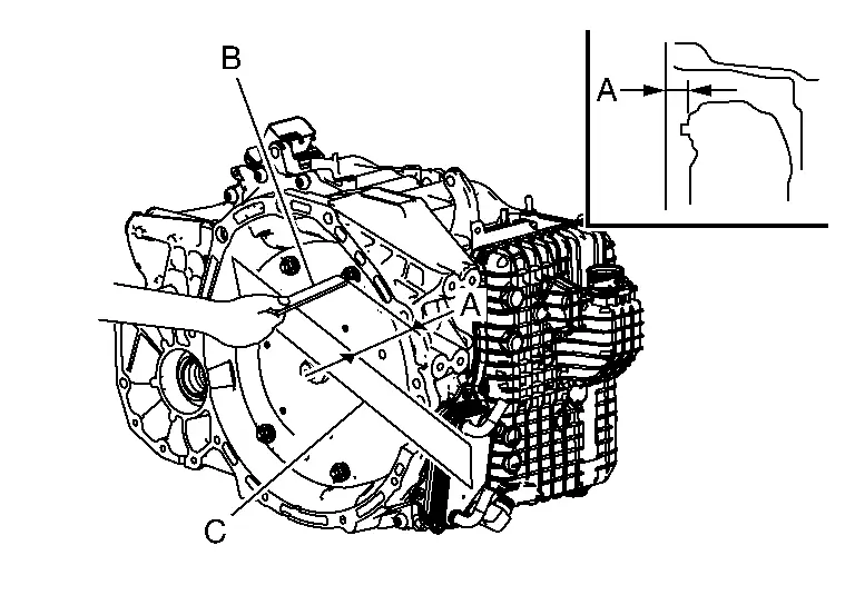
B : Scale C : Straightedge Dimension (A) : Refer to Torque Converter.
Service Data and Specifications (SDS) Nissan Pathfinder Fifth generation
General Specification
| Applied model | Engine | VQ35DD | |
| Axle | 2WD/4WD | ||
| Transmission model | GE9F01A | ||
| Transmission gear ratio | 1st | 4.713 | |
| 2nd | 2.842 | ||
| 3rd | 1.909 | ||
| 4th | 1.382 | ||
| 5th | 1.000 | ||
| 6th | 0.808 | ||
| 7th | 0.699 | ||
| 8th | 0.580 | ||
| 9th | 0.480 | ||
| Reverse | 3.830 | ||
| Final gear | 4.334 | ||
| A/T fluid | Recommended fluid | Nissan Matic R*1 | |
| Capacity (Approx.) | Without Tow Package | With Tow Package | |
| 7.2 L (7-5/8 US qt, 6-3/8 lmp qt)*2 | 7.5 L (7-7/8 US qt, 6-5/8 lmp qt)*2 | ||
*1: Always use the designated stock of A/T fluid. Using or mixing A/T fluid other than the designated stock or using it incorrectly could result in an inability to achieve original performance, or may cause a serious accident.
*2: The A/T fluid amount is only a guide.
Vehicle Speed at Which Gear Shifting Occurs
STANDARD/SPORT/ECO
Unit: km/h (MPH)
| Gear position | Accelerator pedal | |
|---|---|---|
| 100% | 50% | |
| D1 → D2 | 41 – 46 (25 – 29) | 26 – 36 (16 – 22) |
| D2 → D3 | 70– 75 (43– 47) | 45 – 66 (28 – 41) |
| D3 → D4 | 103– 108 (64– 67) | 70 – 108 (43 – 67) |
| D4 → D5 | 143– 148 (89– 92) | 97 – 148 (60 – 92) |
| D5 → D6 | 187– 192 (116– 119) | 127 – 193 (79 – 120) |
| D6 → D7 | 232– 237 (144– 147) | 151 – 237 (94 – 147) |
| D7 → D8 | 262 – 267 (163 – 166) | 171 – 267 (106 – 166) |
| D8 → D9 | 262 – 267 (163– 166) | 198 – 267 (123 – 166) |
| D9 → D8 | 234 – 307 (145 – 191) | 178 – 248 (111 – 154) |
| D8 → D7 | 243 – 255 (151 – 158) | 155 – 248 (96 – 154) |
| D7 → D6 | 209 – 221 (130 – 137) | 133 – 184 (83 – 114) |
| D6 → D5 | 168 – 179 (104 – 111) | 108 – 148 (67 – 92) |
| D5 → D4 | 121 – 130 (75 – 81) | 71 – 109 (44 – 68) |
| D4 → D3 | 93 – 97 (58 – 60) | 53 – 73 (33 – 45) |
| D3 → D2 | 53 – 64 (33 – 40) | 36 – 46 (22 – 29) |
| D2 → D1 | 16 – 35 (10 – 22) | 1 – 20 (1 – 12) |
Torque Converter
Unit: mm (in)
| Distance between the converter housing and torque | 17.4 - 17.9 (0.685 - 0.705) |

Nissan Pathfinder (R53) 2022-2026 Service Manual
9at: Ge9f01a
- Precautions ➤
- Preparation
- Symptom Diagnosis. System Symptom
- Periodic Maintenance. A/t Fluid
- Unit Removal and Installation. Transaxle Assembly ➤
- Unit Disassembly and Assembly. Torque Converter and Converter Housing Oil Seal
- Service Data and Specifications (SDS)
Contact Us
Nissan Pathfinder Info Center
Email: info@nipathfinder.com
Phone: +1 (800) 123-4567
Address: 123 Pathfinder Blvd, Nashville, TN 37214, USA
Working Hours: Mon–Fri, 9:00 AM – 5:00 PM (EST)
