Nissan Pathfinder: Engine Mechanical - Basic Inspection
Camshaft Valve Clearance Nissan Pathfinder Fifth generation
Valve Clearance
CHECKING
CAUTION:
Check valve clearance while engine is cold and not running.
![]() NOTE:
NOTE:
Perform valve clearance inspection after removal, installation or replacement of camshaft or valve parts, or as necessary.
-
Remove the rocker cover (bank 1) and rocker cover (bank 2). Refer to Removal and Installation (Bank 1) (Bank 1) and Removal and Installation (Bank 2) (Bank 2).
-
Set No.1 cylinder at TDC on its compression stroke.

: Engine front -
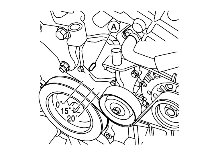
Align pointer (A) with TDC mark (0°) on crankshaft pulley.
-
Check that the valve lifters on No.1 cylinder are loose and valve lifters on No.4 are tight. If not, turn the crankshaft one full revolution (360°) and align as shown.
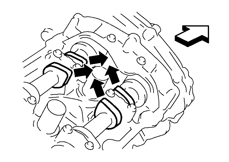

: Engine front
-
-
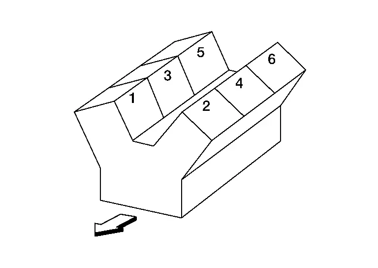
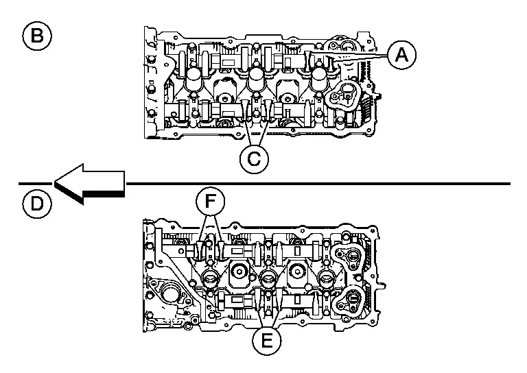
Check only the valves as shown.
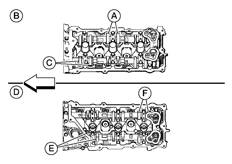
Crank Position Valve No. 1 Valve No. 2 Valve No. 3 Valve No. 6 No. 1 TDC Intake (C) Exhaust (E) Exhaust (A) Intake (F) (B) : Bank 1 (D) : Bank 2 
: Engine front -
Using suitable tool, measure the clearance between the valve lifter and camshaft.
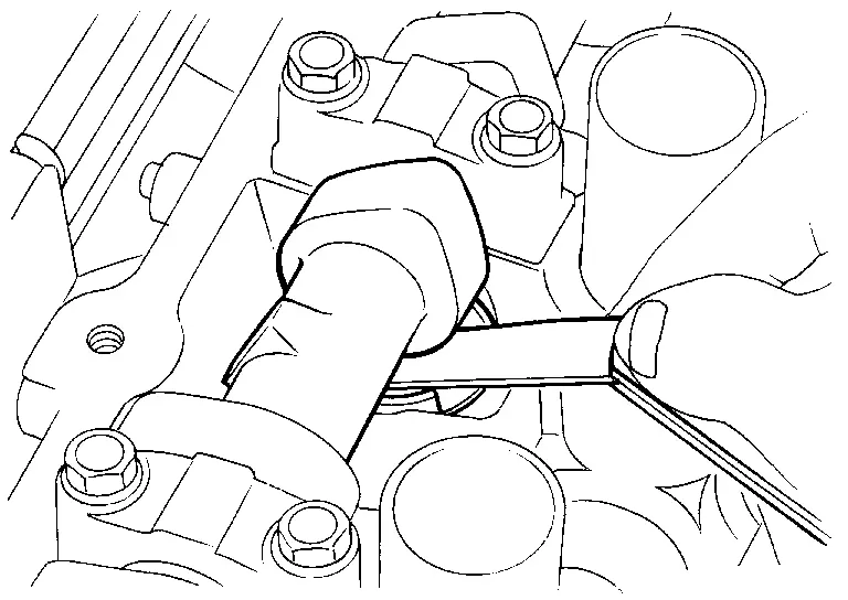
Valve clearance : Refer to Camshaft. -
Record any valve clearance measurements which are out of specification. They will be used later to determine the required replacement lifter size.
-
-
Turn crankshaft 240°.
-
Set No.3 cylinder at TDC on its compression stroke.
-
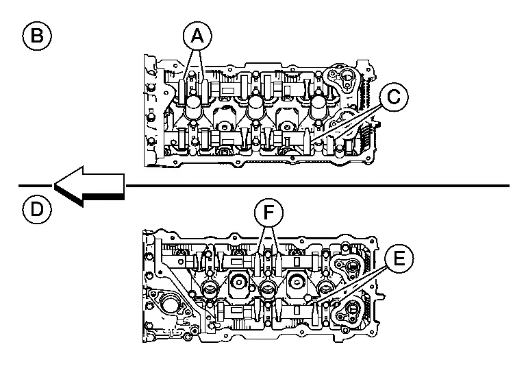
Check only those valves as shown.
Crank Position Valve No. 2 Valve No. 3 Valve No. 4 Valve No. 5 No. 3 TDC Intake (F) Intake (C) Exhaust (E) Exhaust (A) (B) : Bank 1 (D) : Bank 2 
: Engine front -
Turn the crankshaft 240° and align as above.
-
Set No.5 cylinder at TDC on its compression stroke.
-
Check only those valves as shown.
Crank Position Valve No. 1 Valve No. 4 Valve No. 5 Valve No. 6 No. 5 TDC Exhaust (A) Intake (F) Intake (C) Exhaust (E) (B) : Bank 1 (D) : Bank 2 
: Engine front -
Perform adjustment if the measured values are out of the specification range.
-
Installation of components is in the reverse order of removal.
VALVE ADJUSTING
CAUTION:
Adjust valve clearance while engine is cold.
![]() NOTE:
NOTE:
-
Perform adjustment by selecting the correct head thickness of the valve lifter (adjusting shims are not used).
-
The specified valve lifter thickness dimension is measured at room temperature.
-
Use specifications for hot engine for hot engine condition to confirm valve clearances.
-
Remove the camshaft. Refer to Removal and Installation.
-
Remove the valve lifter that was measured as being outside the standard specifications.
-
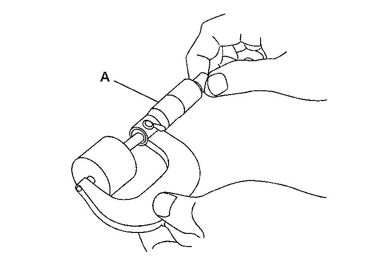
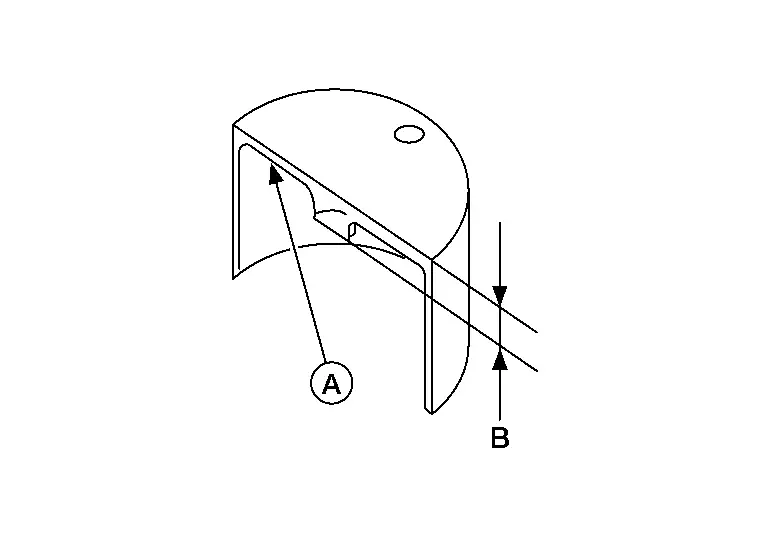
Measure the center thickness of the removed valve lifter using suitable tool (A) as shown.
-
Use the equation below to calculate the replacement valve lifter thickness.
Valve lifter thickness calculation: (C1 – C2) + t1=t C1 = measured valve clearance C2 = standard valve clearance t1 = thickness of the removed valve lifter t = thickness of the replacement valve lifter -
The thickness of the new valve lifter can be identified by the stamp mark (A) on the reverse side (inside the valve lifter).
 NOTE:
NOTE:
Available thicknesses of the valve lifters (B) are: 3.00 - 3.50 mm (0.1181 - 0.1378 in), in 0.02 mm (0.0008 in) increments. Refer to Camshaft.
-
-
Install the selected replacement valve lifter.
-
Install the camshaft. Refer to Removal and Installation.
-
Rotate the crankshaft a few turns by hand.
-
Confirm that the valve clearances are within specification.
-
After the engine has been run to full operating temperature, confirm that the valve clearances are within specification.
Standard : Refer to Camshaft.
Compression Pressure Nissan Pathfinder
On-Vehicle Service
-
Warm up engine to full operating temperature. Stop engine.
-
Release the fuel pressure. Refer to Work Procedure.
-
Remove the fuel pump fuse from IPDM E/R to avoid fuel injection during measurement.
-
Remove ignition coil and spark plug for each cylinder. Refer to Removal and Installation.
-
Install compression tester with adapter into spark plug hole.
 NOTE:
NOTE:
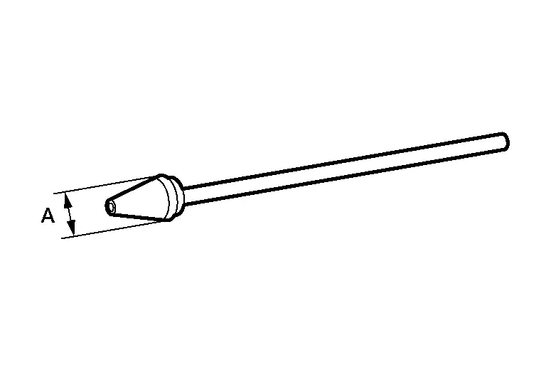
Use compression tester whose end (A) (rubber portion) is smaller than 20 mm (0.79 in) in diameter. Otherwise, it may be caught by cylinder head during removal.
-
With accelerator pedal fully depressed, crank engine. When the gauge pointer stabilizes, read the compression pressure andthe engine rpm. Perform these steps to check each cylinder.
CAUTION:
Always use a fully charged battery to obtain specified engine speed.
Compression pressure : Refer to General Specification. -
If the engine speed is out of the specified rpm range, check the battery. Check the engine speed again with a fully charged battery.
-
If some cylinders have low compression pressure, pour a small amount of engine oil into the spark plug hole of the cylinder to re-check it for compression.
-
If the added engine oil improves the compression, piston rings may be worn out or damaged. Check the piston rings and replace if necessary.
-
If the compression pressure remains at low level despite the addition of engine oil, the valves may be malfunctioning. Check the valves for damage. Replace the valve or valve seat accordingly.
-
-
If two adjacent cylinders have respectively low compression pressure and their compression remains low even after the addition of engine oil, cylinder head gaskets may be leaking, or a valve in adjacent cylinders may be damaged. Inspect and repair as required.
-
If the compression pressure is below the minimum value, check the valve clearances and parts associated with the combustion chamber (valve, valve seat, piston, piston ring, cylinder bore, cylinder head, cylinder head gasket). After the checking, measure the compression pressure again.
-
-
After inspection is completed, installation of the components is in the reverse order of removal.
-
Start the engine and check that engine runs smoothly.
-
Perform trouble diagnosis. If DTC appears, erase it. Refer to Description.

Nissan Pathfinder (R53) 2022-2026 Service Manual
Basic Inspection
Contact Us
Nissan Pathfinder Info Center
Email: info@nipathfinder.com
Phone: +1 (800) 123-4567
Address: 123 Pathfinder Blvd, Nashville, TN 37214, USA
Working Hours: Mon–Fri, 9:00 AM – 5:00 PM (EST)
