Nissan Pathfinder: Steering System - Steering Gear and Linkage
Exploded View
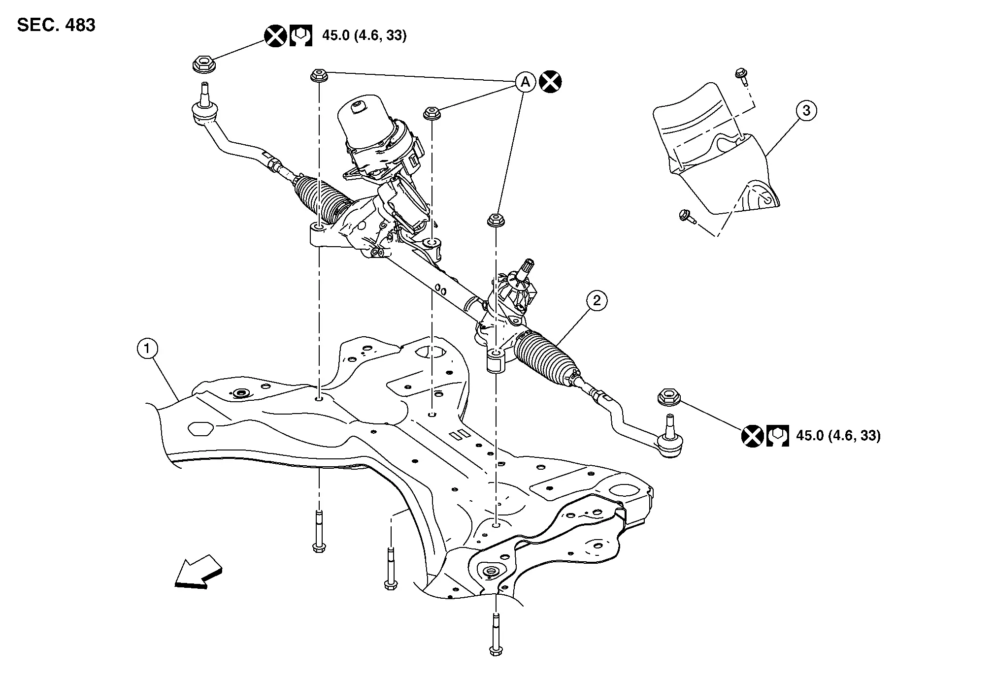
| 1. | Front suspension member | 2. | Steering gear and linkage assembly | 3. | Heat shield |
| A. | Refer to Installation. |
 |
Front |
Removal and Installation
WARNING:
-
Situate the vehicle on a flat and solid surface.
-
Place chocks at front and back of rear wheels.
-
For engines not equipped with engine slingers, attach proper slingers and bolts described in PARTS CATALOG.
CAUTION:
-
Always work safely.
-
Do not start work until the engine and exhaust system are cooled completely.
-
Refer to the applicable sections for warnings, cautions, notes, and instructions if necessary procedures are not included in the engine section.
-
For supporting, lifting and jacking points, refer to Garage Jack and Safety Stand and 2-Pole Lift.
-
Always use the support point specified for lifting.
-
Support the Nissan Pathfinder vehicle at the rear axle jacking point with transmission jack or similar tool before removing the engine in preparation for the backward shift of the center of gravity.
 NOTE:
NOTE:
-
When removing components such as hoses, tubes/lines, etc., cap or plug openings to prevent fluid from spilling.
-
Remove the engine and transaxle with the front suspension member as a unit. Separate the engine from the transaxle and remove from the front suspension member.
REMOVAL
Release fuel pressure. Refer to Work Procedure.
Drain engine coolant. Refer to Draining.
CAUTION:
-
Perform this step when the engine is cold.
-
Do not allow the engine coolant to contact the drive belts.
Recycle the refrigerant. Refer to Recycle Refrigerant.
Remove the cowl top and cowl top extension. Refer to Removal and Installation.
Remove the core support cover. Refer to Exploded View.
Remove the front air duct. Refer to Exploded View.
Remove the air cleaner assembly. Refer to Removal and Installation.
Remove the battery and battery tray. Refer to Removal and Installation.
Disconnect the harness connectors from the ECM. Refer to Harness Connector (LEVER LOCKING TYPE).
Remove the ECM and ECM bracket. Refer to Exploded View.
Remove the front wheels and tires using power tool. Refer to Removal and Installation.
Partially remove the front fender protectors. Refer to Exploded View.
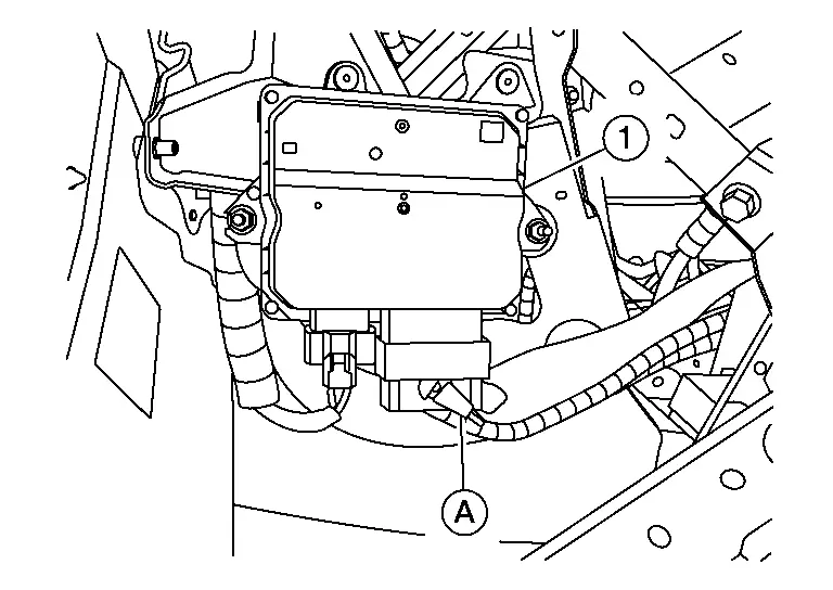
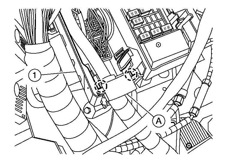
Disconnect the harness connector (A) from the electric intake valve timing control module (1).
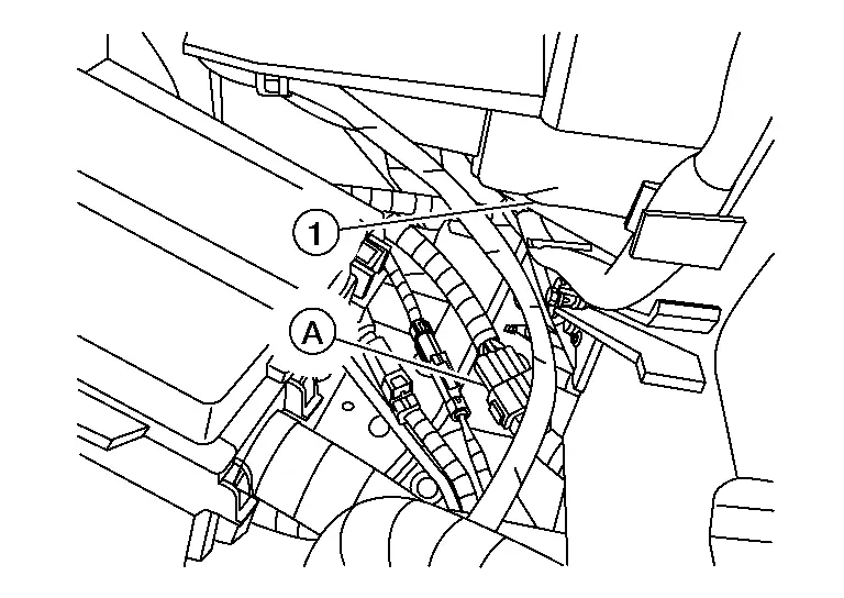
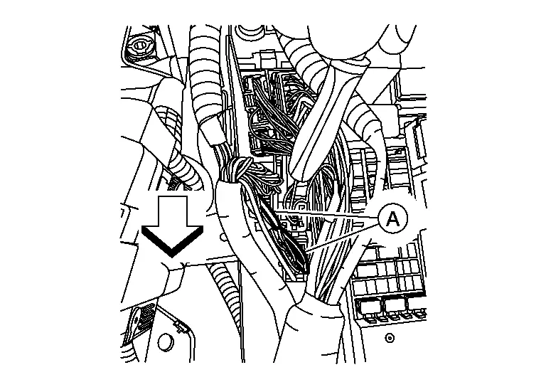
Release harness retainer and reposition engine harness into engine room.
Disconnect harness connector (A).
| (1) | : Front combination lamp (LH) |
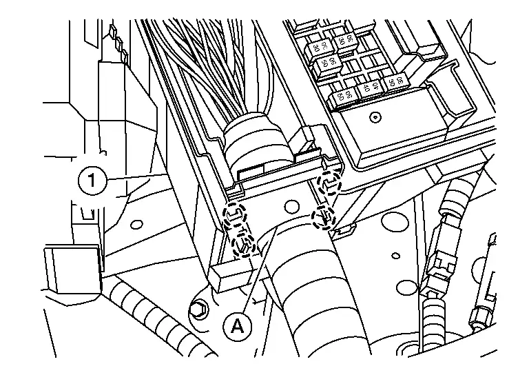
Remove the fuse block cover.
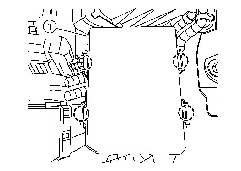
Release fuse block cover A (A) pawls from the fuse block (1) and remove the fuse block cover A.
 |
: Pawl |
Reposition engine harness.
Release fuse block cover B (A) pawls from the fuse block (1) and remove the fuse block cover B.
 |
: Pawl |
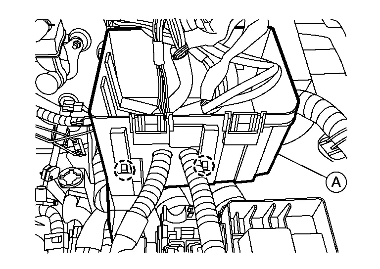
Disconnect the harness connectors (A) from the fuse block.
 |
: Front |
Release the pawls and separate the IPDM E/R (1) from the IPDM E/R case.
 |
: Pawl |
Release pawls and remove the IPDM E/R cover (A) from the IPDM E/R housing.
 |
: Pawl |
Disconnect the harness connector (A) from the IPDM E/R.
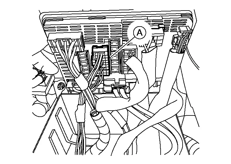
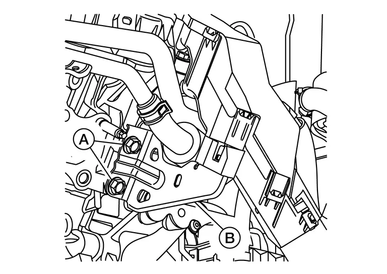
Remove bolt (A) and nut (B) and reposition engine harness.
Remove the radiator hose (upper) from the water outlet pipe. Refer to Exploded View.
Remove the fuel line protector and disconnect the fuel feed using suitable tool. Refer to Exploded View.
Remove the EVAP hose from the vacuum delay valve. Refer to Exploded View.
Remove the vacuum hose from the intake manifold. Refer to Exploded View.
Remove the high-pressure flexible hose from the high-pressure pipe. Refer to Exploded View.
Remove the low-pressure flexible hose from the low-pressure pipe. Refer to Exploded View.
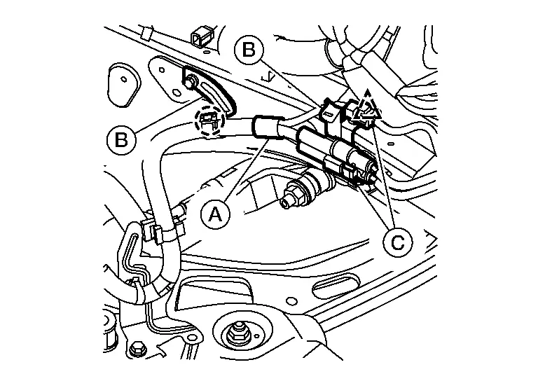
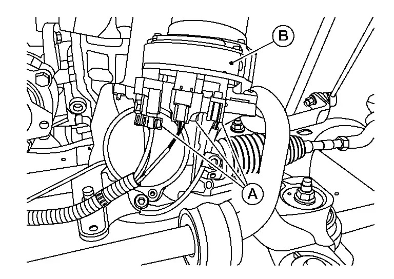
Disconnect the harness connectors (C) for the steering gear and linkage assembly harness (A) and remove the harness from brackets (B).
 |
: Clip |
 |
: Pawl |
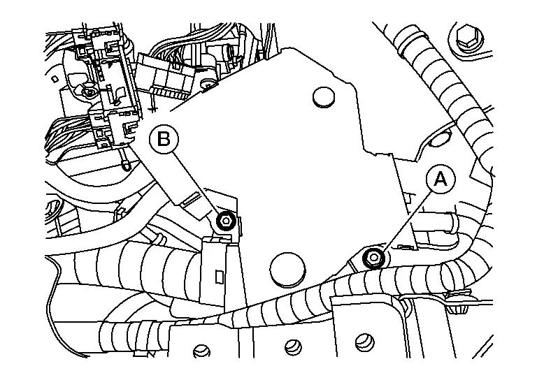
Remove bolt (A) and remove the ground cable from the front cover and release harness retainer (B) from bracket.
| (1) | : Valve timing control cover (bank 2) |
Remove the engine mounting insulator (RH).
Remove the ground cable from the transaxle assembly.
Remove the A/T fluid cooler hoses from the A/T fluid warmer using the following procedure:Remove the A/T fluid cooler hose cap (1) from the A/T fluid cooler hose (2).
| (A) | : Suitable tool |
Remove the front exhaust tube. Refer to Exploded View.
Remove the propeller shaft assembly. Refer to Removal and Installation (4WD models only).
Remove the rear plate cover. Refer to Exploded View.
Rotate engine and remove the torque converter nuts. Refer to Exploded View.
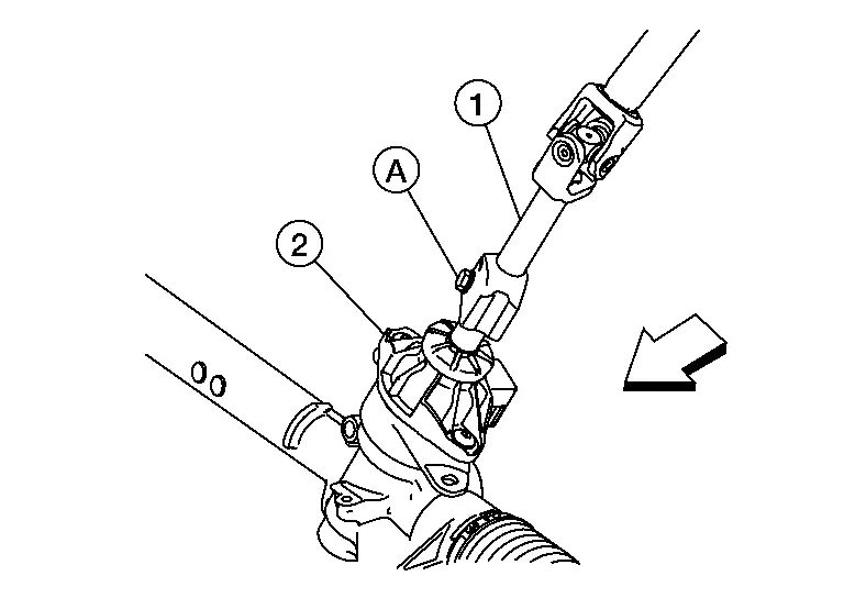
Remove steering pinch bolt and separate the lower joint from steering gear and linkage. Refer to Exploded View.
CAUTION:
With the steering linkage disconnected, the spiral cable may snap by turning the steering wheel beyond the limited number of turns. Secure the steering wheel during removal of the steering gear.
Remove the front disc brake rotor (RH/LH). Refer to Removal and Installation.
Remove wheel sensor bolt and position wheel sensor aside. Refer to Removal and Installation.
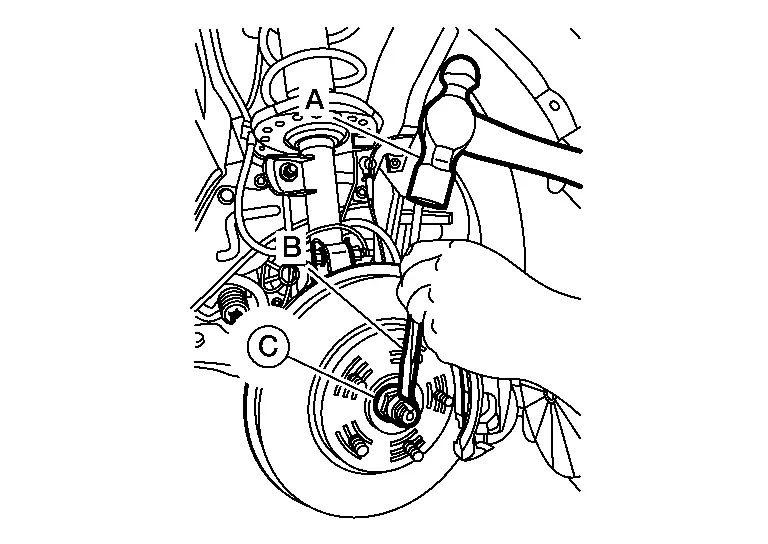
Using suitable tool (A) and Tool (B), release staked area (C) of wheel hub lock nut (D).
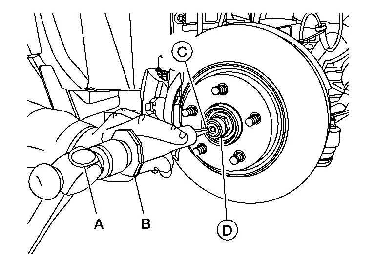
| Tool (B) | : — (J-52982) |
Visually verify that staked area (A) of wheel hub lock nut (B) is completely released from front drive shaft (1) or damage to drive shaft can occur.
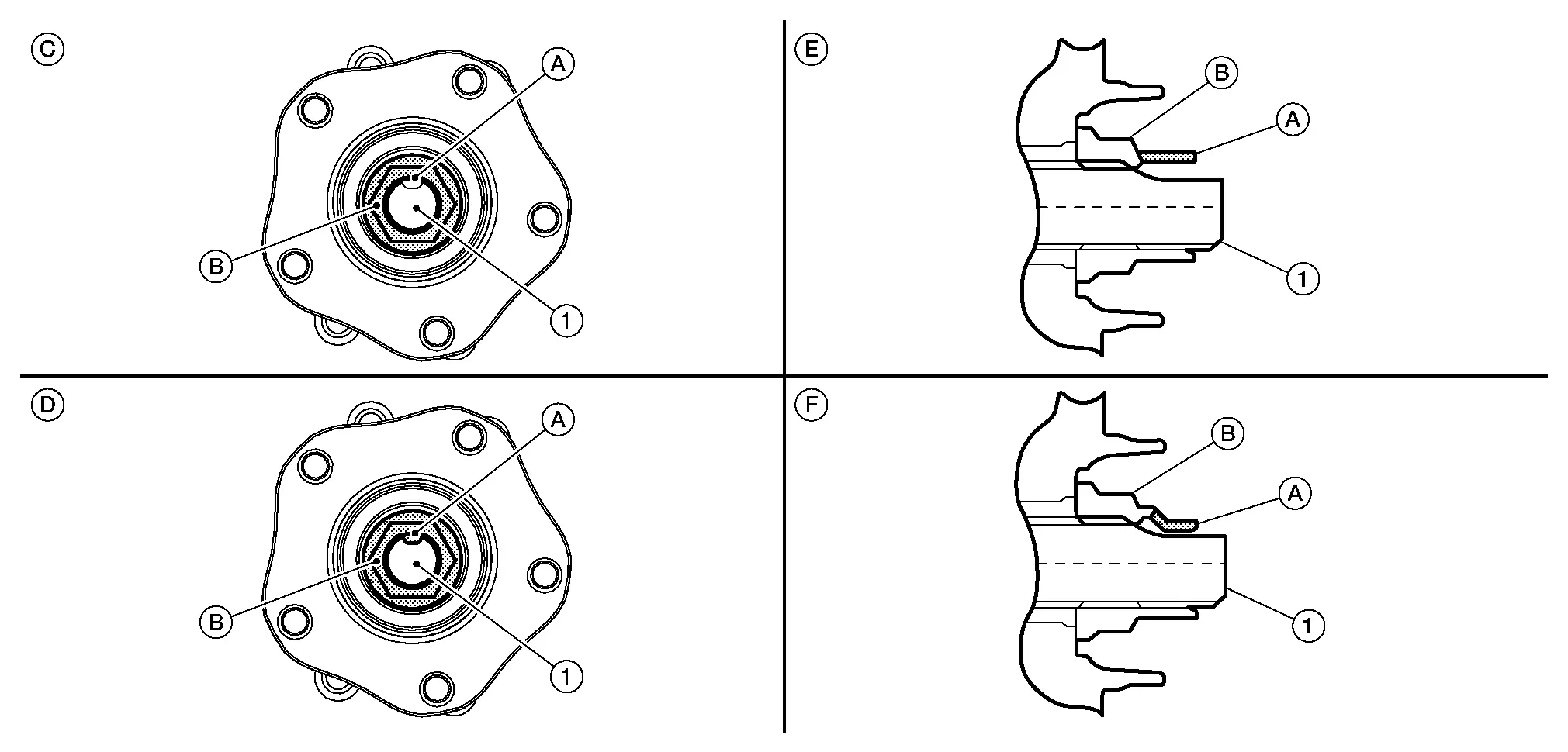
| (C) | : Fully released |
| (D) | : Not fully released |
| (E) | : Fully released (sectional view) |
| (F) | : Not fully released (sectional view) |
WARNING:
To avoid risk of death or severe personal injury:
-
Be sure that staked area of wheel hub lock nut is fully released or damage to drive shaft can occur.
-
Do not damage front drive shaft threads.
Loosen lock nut from drive shaft.
WARNING:
To avoid risk of death or severe personal injury:
-
Do not use power tools.
-
Do not damage front drive shaft threads.
-
Do not reuse drive shaft lock nut.
-
When loosening lock nut, if it does not turn smoothly, verify that staked area is completely released.
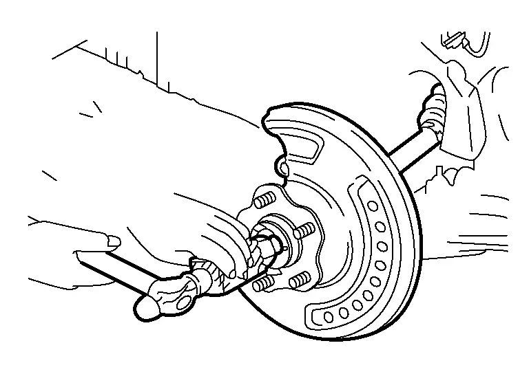
Using a piece of wood and a suitable tool, tap on the lock nut to disengage drive shaft from wheel hub and bearing.
WARNING:
To avoid risk of death or severe personal injury:
-
Do not place drive shaft joint at an extreme angle. Be careful not to over extend slide joint.
-
Do not allow drive shaft to hang without support.
 NOTE:
NOTE:
Use suitable puller if drive shaft cannot be separated from wheel hub and bearing assembly.
Remove wheel hub lock nut.
WARNING:
To avoid risk of death or severe personal injury:
-
Do not reuse wheel hub lock nut.
Loosen outer socket nut and separate outer socket from steering knuckle using suitable tool.
CAUTION:
Leave the outer socket nut half threaded on the outer socket to prevent damage to threads and to prevent the suitable tool from coming off suddenly.
Remove outer socket nut and outer socket.
Remove nuts and bolts and separate the steering knuckle from the strut. Refer to Exploded View.
CAUTION:
Do not reuse nuts.
Remove nuts and separate the stabilizer connecting rod from the strut. Refer to Exploded View.
Remove the bearing retainer bolts and remove the bearing retainer. Refer to Exploded View (RH).
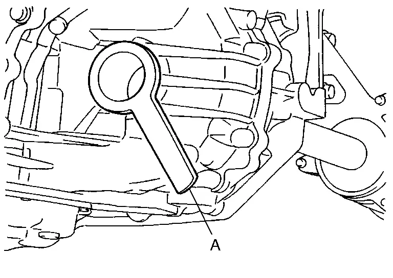
Insert suitable tool (A) between the drive shaft and the transaxle. Remove the drive shaft from the transaxle (LH/RH).
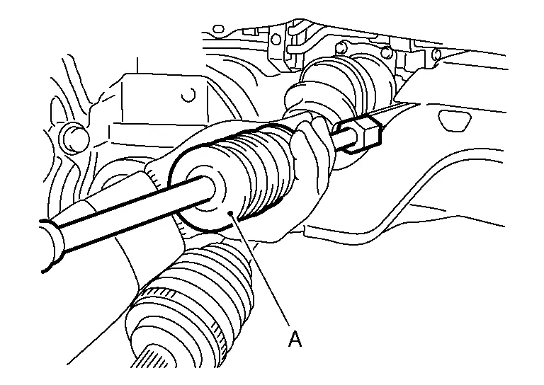
CAUTION:
-
Confirm that the circular clip is attached to the drive shaft
-
Do not place the drive shaft joint at an extreme angle when removing the drive shaft. Also be careful not to overextend the slide joint.
For 2WD models, remove the differential side oil seal (RH/LH). Refer to Exploded View.
CAUTION:
Do not reuse differential side oil seal.
For 4WD models, remove the differential side oil seal (LH). Refer to Exploded View.
CAUTION:
Do not reuse differential side oil seal.
Using a suitable tool, remove suspension member bolts and remove suspension member, engine, and transmission assembly. Refer to Exploded View.
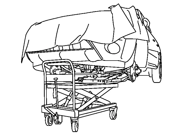
CAUTION:
-
Put a piece of wood or something similar as the supporting surface to secure a completely stable condition.
-
Confirm there is no interference with the Nissan Pathfinder vehicle.
-
Repeatedly check to ensure all harnesses are disconnected before and during engine removal.
-
Check all connection points have been disconnected.
-
Keep in mind the center of Nissan Pathfinder vehicle gravity changes. If necessary, use jack(s) to support the vehicle at rear jacking point(s) to prevent it from falling off the lift.
Remove vacuum hoses from vacuum tube (front). Refer to Exploded View.
Remove bolts and remove the vacuum tube (front). Refer to Exploded View.
Remove bolts (A) and reposition bracket (B) and engine harness.
 NOTE:
NOTE:
Exhaust manifold (bank 2) is removed for clarity.
Install engine slingers into the front of cylinder head (bank 1) and rear of cylinder head (bank 2).
-
Cylinder head (bank 1)
Bolts (A) : Refer to Removal and Installation. -
Cylinder head (bank 2)
Bolts (A) : Refer to Removal and Installation.
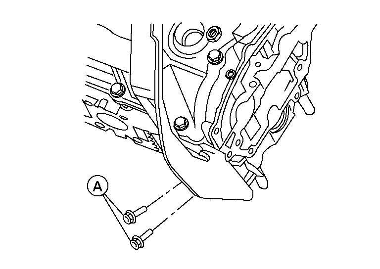
Remove the nut securing the engine mounting bracket (front) to the engine mounting insulator (front). Refer to Exploded View.
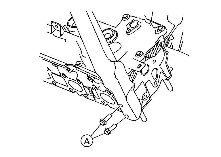
Remove bolts securing engine mounting insulator (LH) to front suspension member. Refer to Exploded View.
Remove the nut securing the engine mounting bracket (rear) to the engine mounting insulator (rear). Refer to Exploded View.
Remove the engine and transaxle assembly from the front suspension member.
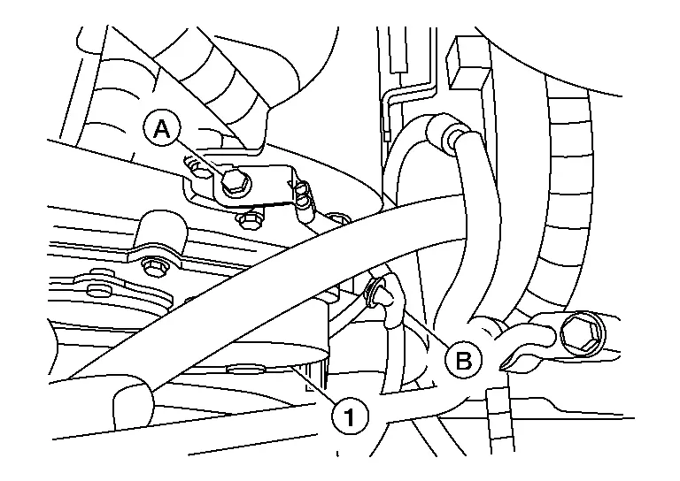
Disconnect harness connectors (A) from EPS motor (B).
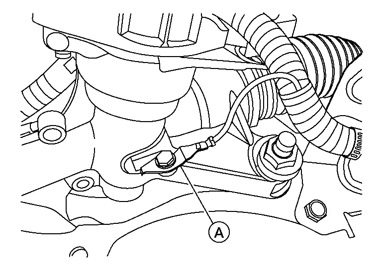
Disconnect ground wire (A) from steering gear housing.
Remove steering gear nuts and bolts, and remove steering gear from front suspension member.
INSTALLATION
Install steering gear to front suspension member with nuts and bolts finger tight, then tighten nuts to specification in the sequence shown.
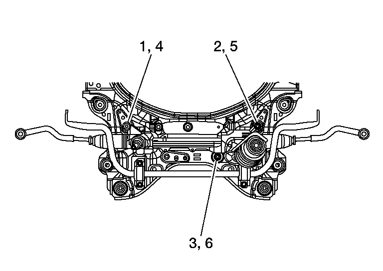
| Nuts | : 145 N·m (15 kg-m, 107 ft-lb) |
Connect harness connectors (A) to EPS motor (B).

Install ground wire (A) to steering gear housing.

CAUTION:
-
When installing lower joint to steering gear, align lower joint yoke bolt hole (B) to steering gear pinion shaft groove (A).
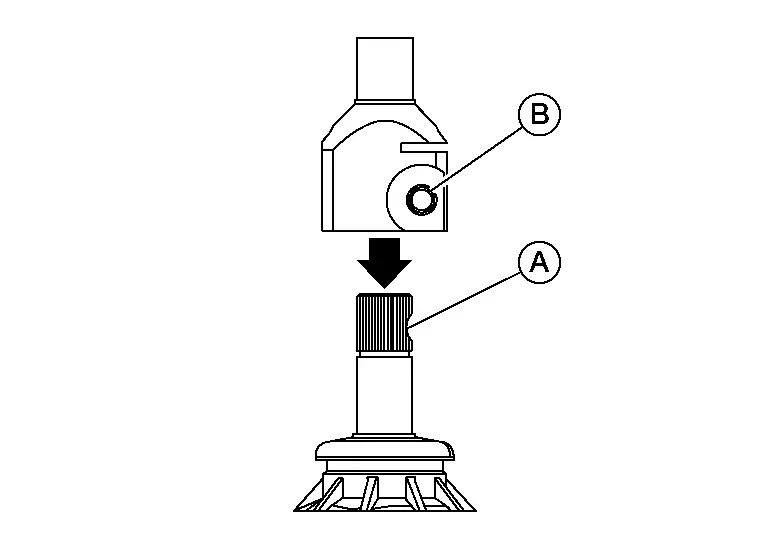
-
Install lower joint (1) pinch bolt (A) finger tight. Verify pinch bolt is properly seated in steering gear (2) pinion shaft groove.
CAUTION:
Bolt (A) is directional.
-
Tighten pinch bolt to specification:
Pinch bolt : 26.5 N·m (2.7 kg-m, 20 ft-lb) -
Check wheel alignment. Refer to Inspection.
-
Perform ADJUSTMENT OF STEERING ANGLE SENSOR NEUTRAL POSITION. Refer to Description.
-
Perform ADDITIONAL SERVICE WHEN REPLACING EPS CONTROL UNIT. Refer to Work Procedure.
Installation of remaining components is in the reverse order of removal.
-
If engine mounting insulator (LH) is removed from transaxle assembly, install and tighten bolts to the specified torque.
Engine mounting insulator (LH) bolt : Refer to Exploded View. -
After installation of engine and transaxle assembly, refer to Inspection.
-
Refill the engine coolant. Refer to Refilling.
-
Recharge refrigerant. Refer to Charge Refrigerant.
CAUTION:
After charging refrigerant, check for leaks. Refer to Leak Test.
-
When installing the drive shaft (RH/LH), note the following:
-
Install a new differential side oil seal. Refer to Removal and Installation (LH) or Removal and Installation (RH).
-
In order to prevent damage to differential side oil seal, place Tool (A) onto oil seal before inserting drive shaft as shown. Slide drive shaft into slide joint and tap with a suitable tool to install securely.
Tool number : KV38107900 (J-52469-1) -
Install new circlip on drive shaft in the circular clip groove on transaxle side. Refer to Disassembly and Assembly (LH).
WARNING:
Ensure that circular clip is properly engaged, otherwise the joint subassembly could pull away from transaxle during Nissan Pathfinder vehicle operation resulting in loss of drive force and possible drive shaft damage, which may cause a crash and serious injury or damage the drive shaft.
 NOTE:
NOTE:
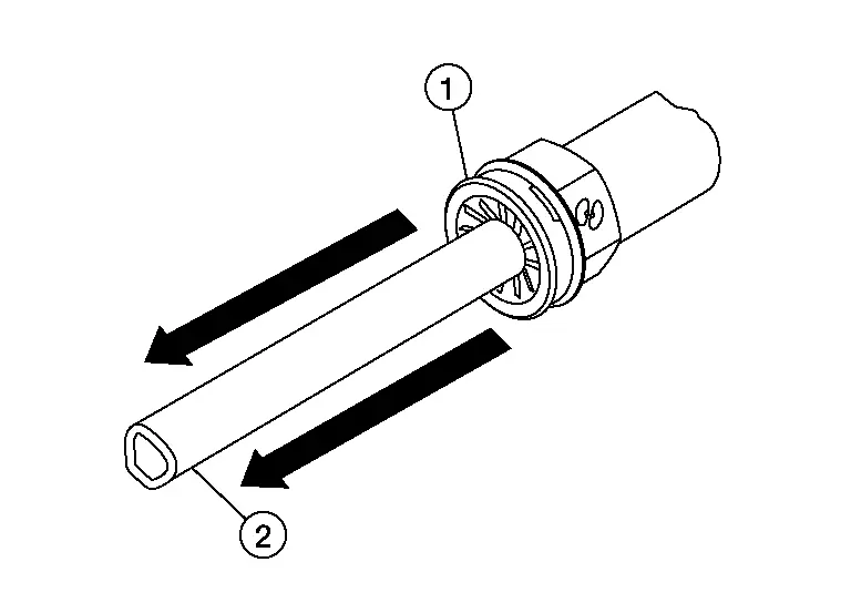
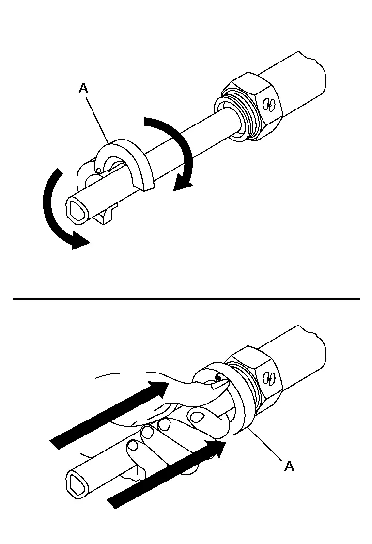
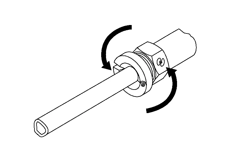
To ensure the circular clip is properly engaged, grasp the housing (1) and pull back and forth in axial direction while listening for clicking sounds.
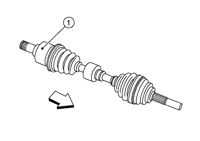
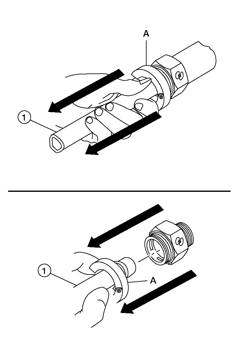
Pull the joint sub-assembly in the axial direction away from transaxle assembly (
 ). Confirm that the joint sub assembly cannot be pulled out.
 -
Clean the matching surface of drive shaft and wheel hub assembly. Apply a moderate coat of paste [service parts (440037S000)] to surface (A) of joint sub-assembly of drive shaft.
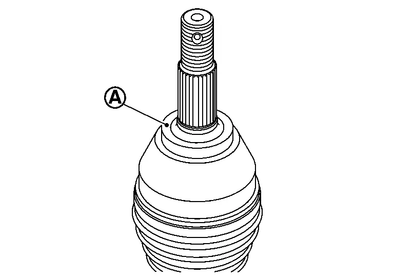
 NOTE:
NOTE:
To avoid damage to the Nissan Pathfinder vehicle:
-
Apply paste to cover entire flat surface of joint sub-assembly of drive shaft.
Paste amount : 1.0 - 3.0 g (0.04 - 0.10 oz) -
Always check with the Parts Department for the latest parts information.
-
-
Hold wheel hub and bearing using a suitable tool. Tighten wheel hub lock nut.
Wheel hub lock nut : Refer to Exploded View (LH) or Exploded View (RH). WARNING:
To avoid risk of death or severe personal injury:
-
Since drive shaft is assembled by press-fitting, use a torque wrench to tighten wheel hub lock nut. Do not use a power tool.
-
Too much torque causes axle noise. Too little torque causes wheel bearing looseness.
-
Do not reuse the wheel hub lock nut.
-
-
Using suitable tool (A) and cold chisel (B) stake the wheel hub lock nut (C) as shown.
WARNING:
To avoid the risk of death or severe personal injury:
-
Use the following range when staking the wheel hub lock nut.
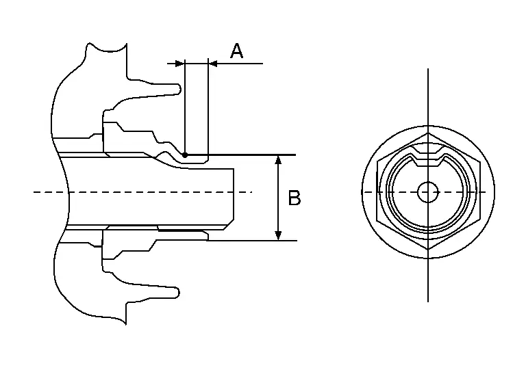
(A) : 6.2 mm (0.244 in) (B) : 26.4 - 27.8 mm (1.039 - 1.094 in) -
-
Tighten the bearing retainer bolts to the specified torque in the sequence shown.
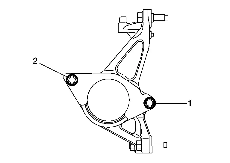
Bearing retainer bolts : Refer to Exploded View (RH).
-
-
Install the exhaust manifold and three way catalyst (bank 1) assembly using the following procedure:
-
Install the exhaust manifold gasket in the direction shown.
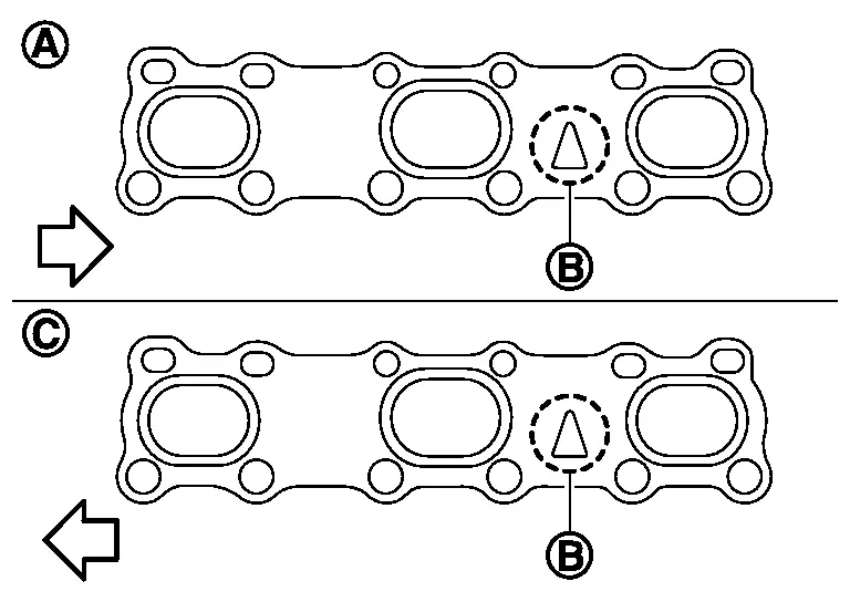
CAUTION:
Do not reuse gasket.
(A) : Bank 1 (B) : Triangle press (C) : Bank 2 
: Engine front -
Install the exhaust manifold (bank 1) nuts and tighten to the specified torque in the sequence shown.
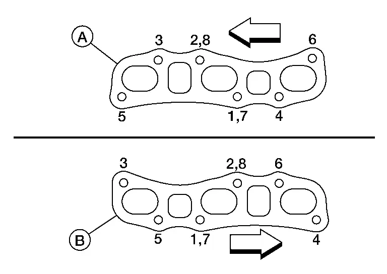
 NOTE:
NOTE:
Number 7 and 8 are tightened a second time.
Exhaust manifold and three way catalyst (bank 1) nuts : Refer to Removal and Installation (bank 1). 
: Engine front (A) : Bank 2 (B) : Bank 1
-

Nissan Pathfinder (R53) 2022-2026 Service Manual
Contact Us
Nissan Pathfinder Info Center
Email: info@nipathfinder.com
Phone: +1 (800) 123-4567
Address: 123 Pathfinder Blvd, Nashville, TN 37214, USA
Working Hours: Mon–Fri, 9:00 AM – 5:00 PM (EST)
