Nissan Pathfinder: Driveline - System Description
Component Parts Nissan Pathfinder R53
4wd System
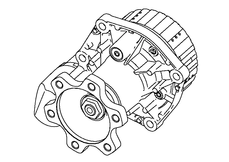
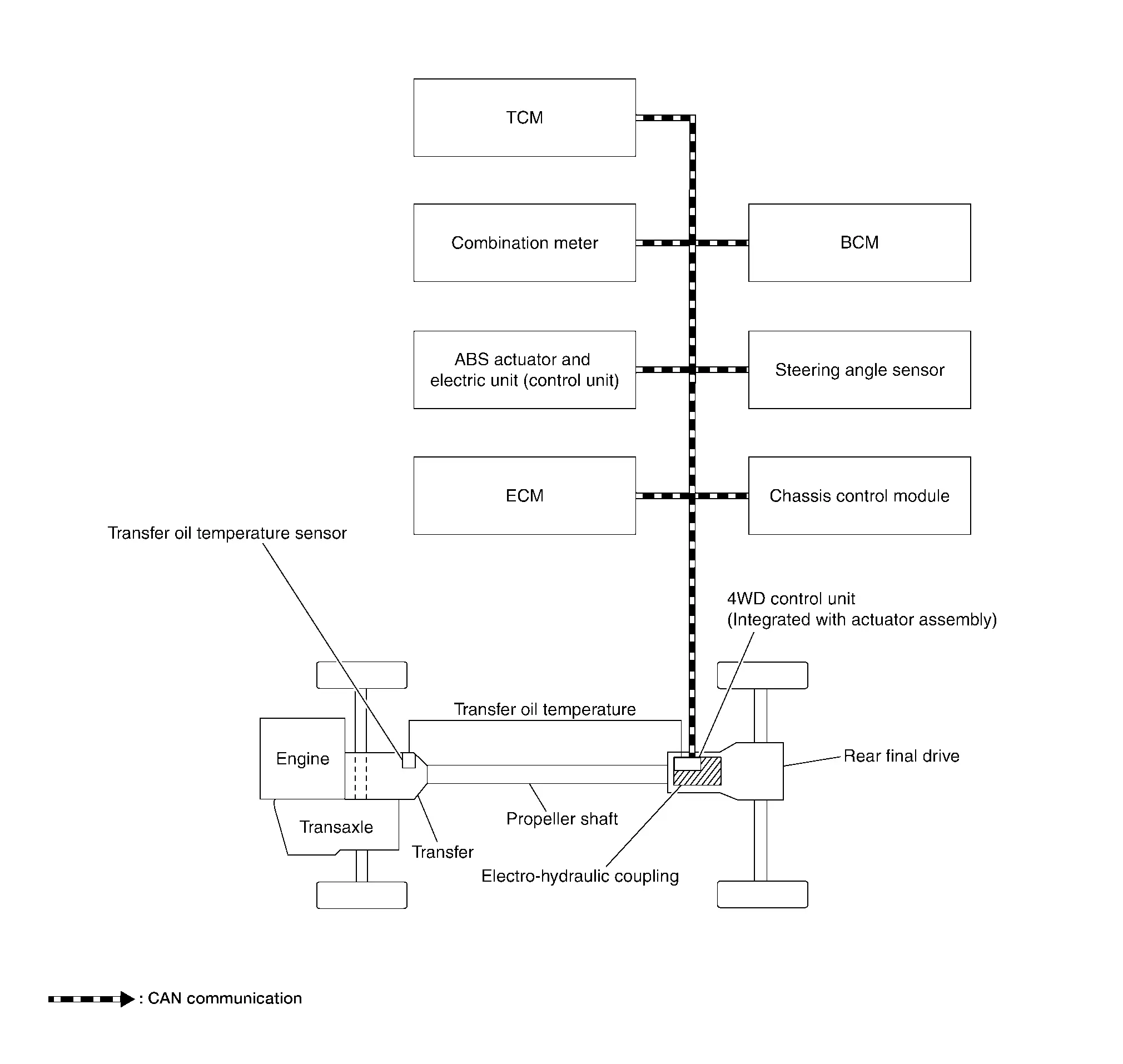
Component Parts Location
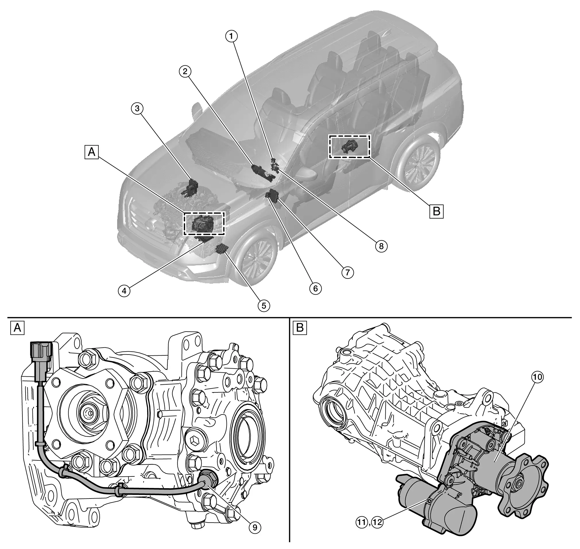
| A. | Transfer case assembly | B. | Rear final drive assembly |
| No. | Component | Function |
|---|---|---|
| 1. | Drive mode switch | Refer to Drive Mode Select Switch for detailed component location. |
| 2. |
Combination meter [4WD (four wheel drive) warning icon/display] |
Transmits/receives the signals for control of 4WD system via CAN communication line to/from 4WD control unit. For transmitting/receiving mainly signals, refer to System Description. Refer to Combination Meter (Full TFT meter) or Combination Meter (7 inch information display) for detailed component location. |
| 3. |
ABS actuator and electric unit (control unit) [Anti-lock Braking System actuator and electric unit (control unit)] |
Transmits/receives the signals for control of 4WD system via CAN communication line to/from 4WD control unit. For transmitting/receiving mainly signals, refer to System Description. Refer to ABS Actuator and Electric Unit (Control Unit) for detailed component location. |
| 4. |
ECM (Engine Control Module) |
Transmits/receives the signals for control of 4WD system via CAN communication line to/from 4WD control unit. For transmitting/receiving mainly signals, refer to System Description. Refer to Component Parts Location for detailed component location. |
| 5. |
TCM (Transmission Control Module) |
Transmits/receives the signals for control of 4WD system via CAN communication line to/from 4WD control unit. For transmitting/receiving mainly signals, refer to System Description. Refer to Component Parts Location for detailed component location. |
| 6. | Chassis control module |
Chassis control module transmits the drive mode signal to ADAS control unit 2 via CAN communication. Refer to Component Parts Location for detailed component location. |
| 7. | BCM (Body Control Module) | Refer to System Description. |
| 8. | Steering angle sensor |
Transmits/receives the signals for control of 4WD system via CAN communication line to/from 4WD control unit. For transmitting/receiving mainly signals, refer to System Description. Refer to Steering Angle Sensor for detailed component location. |
| 9. | Transfer oil temperature sensor |
Transmits transfer oil temperature to the 4WD control unit. Refer to Transfer Oil Temperature Sensor. |
| 10. | Electro-hydraulic coupling | Refer toElectro-hydraulic Coupling. |
| 11. |
4WD control unit (Integrated with actuator assembly) |
Refer to 4WD Control Unit. |
| 12. | Actuator assembly | Integrated into the 4WD control unit and engages rear differential. |
4WD Control Unit
-
4WD control unit is integrated with actuator assembly of electro-hydraulic coupling assembly. For installation location of actuator assembly, refer to Component Parts Location.
-
Controls driving force distribution by signals from each sensor from front wheel driving mode (100:0) to 4-wheel driving mode (50:50).
-
Fail-safe mode is available if malfunction is detected in 4WD system. For fail-safe, refer to Fail-Safe.
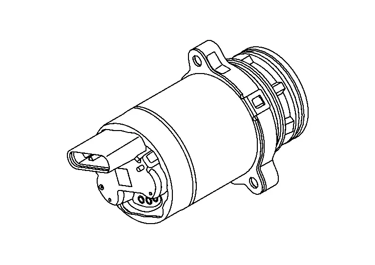
Transfer Oil Temperature Sensor
-
Transfer oil temperature sensor is installed on transfer case.
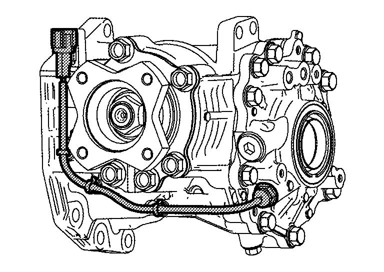
-
Transfer oil temperature sensor detects the transfer oil temperature and transmits a signal to 4WD control unit.
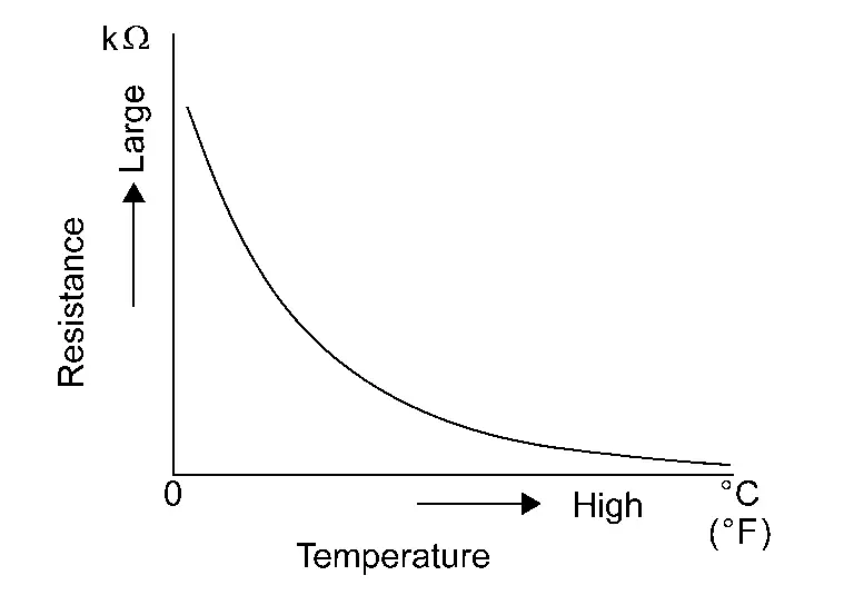
-
The electrical resistance of the sensor decreases as temperature increases.
Electro-hydraulic Coupling
-
Electro-hydraulic coupling is installed on front of rear final drive and transmits driving force to rear final drive.
-
Electro-hydraulic coupling assembly include actuator assembly.
-
For operation, refer to Operation Description.
-
For detailed component location, refer to Component Parts Location.
Structure and Operation Nissan Pathfinder SUV
Sectional View
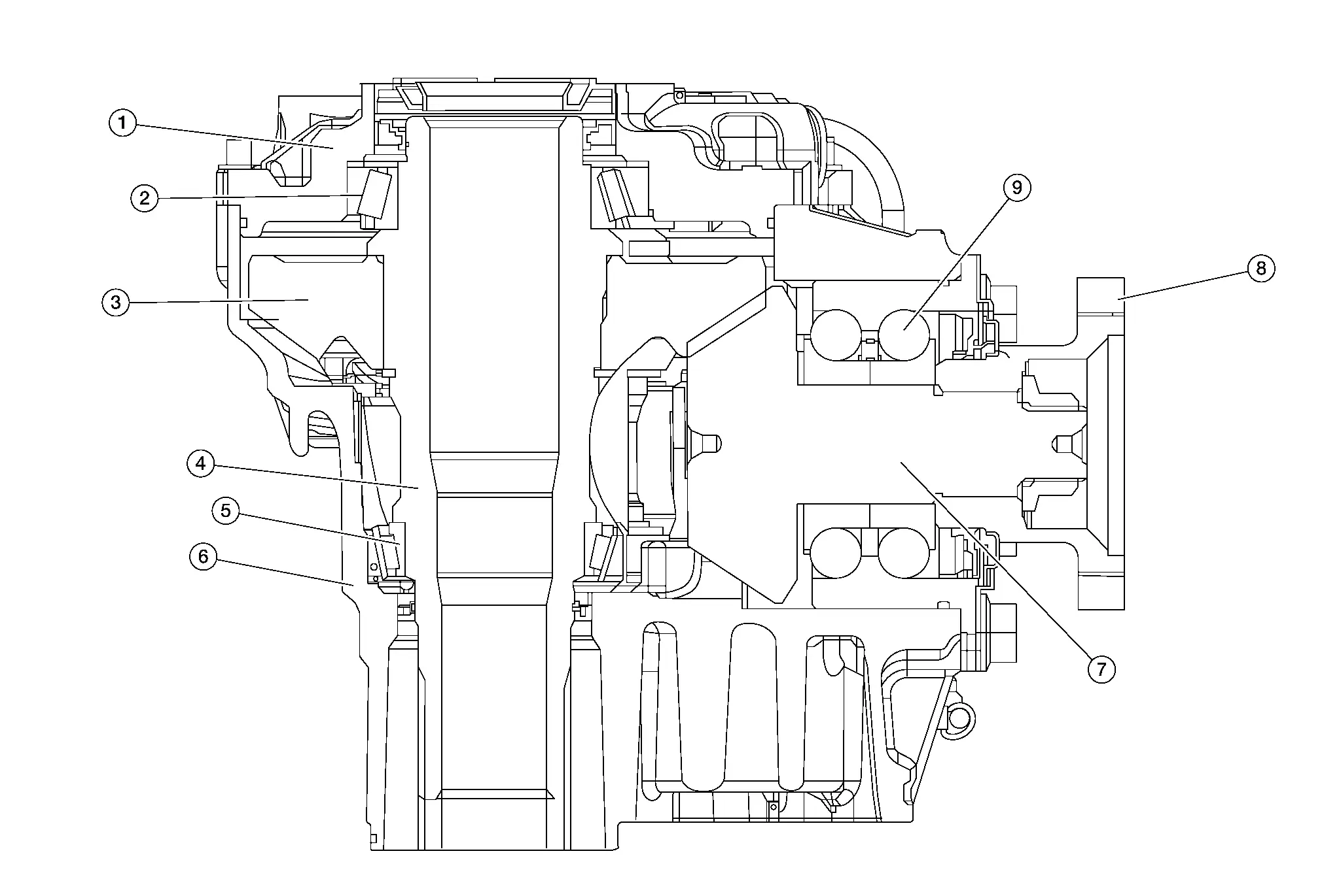
| 1. | Transfer cover | 2. | Ring gear bearing (transfer cover side) | 3. | Ring gear |
| 4. | Ring gear shaft | 5. | Ring gear bearing (transfer case side) | 6. | Transfer case |
| 7. | Drive pinion | 8. | Companion flange | 9. | Pinion bearing |
Operation Description
POWER TRANSFER DIAGRAM
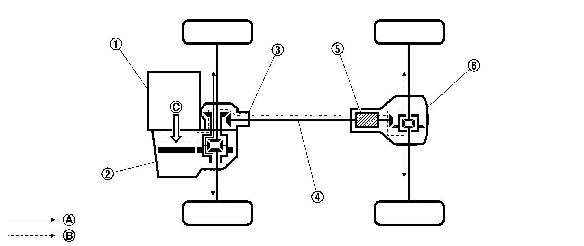
| 1. | Engine | 2. | Transaxle | 3. | Transfer |
| 4. | Propeller shaft | 5. | Electro-hydraulic coupling | 6. | Rear final drive |
| A. | Power transmission to front wheels | B. | Power transmission to rear wheels | C. | Power from engine |
ELECTRO-HYDRAULIC COUPLING
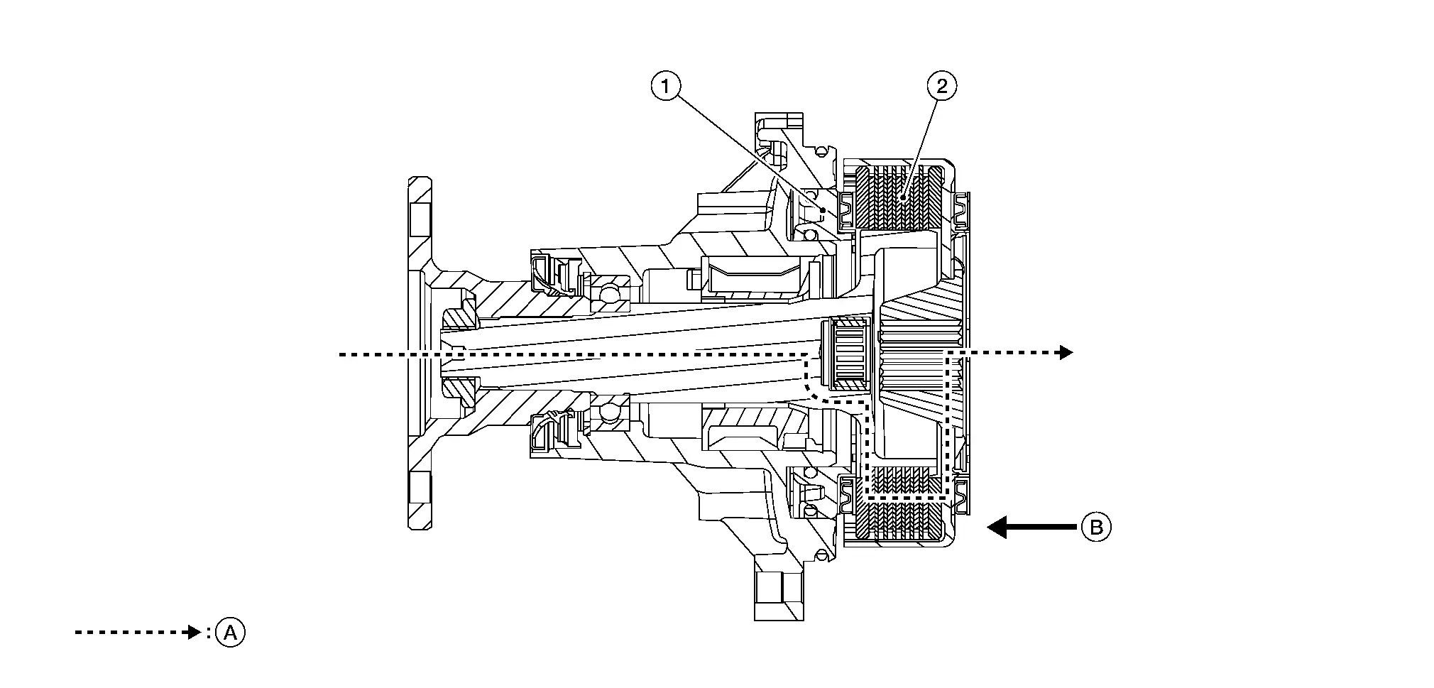
| 1. | Hydraulic piston | 2. | Main clutch | A. | Power transmission to final drive assembly |
| B. | Power supply and CAN communication signal | ||||
-
4WD control unit (integrated with actuator assembly) receives the CAN communication signal from the Nissan Pathfinder vehicle and judges the vehicle condition.
-
The actuator operates according to the command from the 4WD control unit, and the hydraulic piston generates hydraulic pressure according to the Nissan Pathfinder vehicle condition.
-
The main clutch is pressed by the hydraulic pressure generated by the hydraulic piston, and clutch plates (inner side and outer side) are engaged
-
The main clutch transmits torque to rear wheels according to the hydraulic pressure from actuator.
System Nissan Pathfinder 5th Gen
Part Time 4wd System
System Description
SYSTEM DIAGRAM
INPUT/OUTPUT SIGNAL
It transmits/receives each signal from the following 4WD control unit via CAN communication line:
| Component parts | Function |
|---|---|
| ABS actuator and electric unit (control unit) |
Transmits the following signals via CAN communication to 4WD control unit:
|
| ECM |
Transmits the following signals via CAN communication to 4WD control unit:
|
| TCM |
Transmits the following signals via CAN communication to 4WD control unit:
|
| Combination meter |
Receives the following signal via CAN communication from 4WD control unit:
|
| Steering angle sensor | Transmits conditions of steering angle sensor signal via CAN communication to 4WD control unit. |
| Chassis control module |
Mainly transmits the following signal to the 4WD control unit via CAN communication:
|
| BCM |
Mainly transmits the following signal to the 4WD control unit via CAN communication:
|
DESCRIPTION
-
4WD controls distribution of drive power between front-wheel drive (100:0) and 4-wheel drive (50:50) conditions according to signals from sensors.
-
By receiving the steering angle sensor signal, yaw rate sensor signal, side G sensor signal and decel G sensor signal, Nissan Pathfinder vehicle with VDC corrects a torque distribution for front and rear wheels according to a driving operation and a behavior of the Nissan Pathfinder vehicle during cornering and improves drivability and safety on a slippery road surface.
-
Electronic control allows optimal distribution of torque to front/rear wheels to match road conditions.
-
4WD mode makes possible stable driving possible with no wheel spin, on snowy roads or other slippery surfaces.
-
On roads which do not require 4-wheel drive, it contributes to improved fuel economy by driving in conditions close to front-wheel drive.
-
Sensor inputs determine the Nissan Pathfinder vehicle's turning condition, and tight cornering/braking are controlled by distributing optimum torque to rear wheels.
 NOTE:
NOTE:
Light tight-corner braking symptom may occur depending on driving condition. This is not malfunction.
Diagnosis System (awd Control Unit) Nissan Pathfinder 2022
CONSULT Function
CAUTION:
After disconnecting the CONSULT vehicle interface (VI) from the data link connector, the ignition must be cycled OFF —> ON (for at least 5 seconds) —>OFF. If this step is not performed, the BCM may not go to ”sleep mode”, potentially causing a discharged battery and no-start condition.
APPLICATION ITEMS
CONSULT can display each diagnostic item using the diagnostic test modes as follows:
| Diagnostic test mode | Function |
|---|---|
| ECU Identification | 4WD control unit part number can be read. |
| Self Diagnostic Result | Self-diagnostic results and freeze frame data can be read and erased quickly.* |
| Data Monitor | Input/Output data in the 4WD control unit can be read. |
| Work support | This mode enable a technican to adjust some devices faster and more accurately by following the indication on the CONSULT. |
*: The following diagnosis information is erased by erasing:
-
DTC
-
Freeze frame data (FFD)
ECU IDENTIFICATION
4WD control unit part number can be read.
SELF DIAGNOSTIC RESULT
Refer to DTC Index.
When “PRSNT” is displayed on self-diagnosis result.
-
The system is presently malfunctioning.
When “PAST” is displayed on self-diagnosis result.
-
System malfunction in the past is detected, but the system is presently normal.
FREEZE FRAME DATA (FFD)
The following vehicle status is recorded when DTC is detected and is displayed:
| Freeze Frame Data Item | Description |
|---|---|
| IGN COUNTER [0 - 39] |
The number of times that ignition switch is placed ON after the DTC is detected is displayed.
|
 NOTE:
NOTE:
DATA MONITOR
 NOTE:
NOTE:
The following table includes information (items) inapplicable to this Nissan Pathfinder vehicle: For information (items) applicable to this vehicle, refer to CONSULT display items.
| Monitor item (Unit) | Remarks | ||
|---|---|---|---|
| Battery voltage (V) | Power supply voltage value of 4WD control unit is displayed. | ||
| Front RH wheel speed (mph or km/h) | Wheel speed calculated by front RH wheel sensor signal is displayed. | ||
| Front LH wheel speed (mph or km/h) | Wheel speed calculated by front LH wheel sensor signal is displayed. | ||
| Rear RH wheel speed (mph or km/h) | Wheel speed calculated by rear RH wheel sensor signal is displayed. | ||
| Rear LH wheel speed (mph or km/h) | Wheel speed calculated by rear LH wheel sensor signal is displayed. | ||
| Warning lamp (On/Off) | Control status of 4WD warning (on information display) is displayed. | ||
| Different diameter tire monitor (mm) | Improper size tire installed condition is displayed. | ||
WORK SUPPORT
| Item | Usage |
|---|---|
| BLEED AIR & INITIALIZE OIL DETERIORATION LEVEL | Air bleeding in oil passage and initialize oil deterioration level of electro-hydraulic coupling oil of 4WD control unit. |

Nissan Pathfinder (R53) 2022-2026 Service Manual
System Description
Contact Us
Nissan Pathfinder Info Center
Email: info@nipathfinder.com
Phone: +1 (800) 123-4567
Address: 123 Pathfinder Blvd, Nashville, TN 37214, USA
Working Hours: Mon–Fri, 9:00 AM – 5:00 PM (EST)
