Nissan Pathfinder: Wiper & Washer - System
Front Wiper and Washer System Nissan Pathfinder 2022
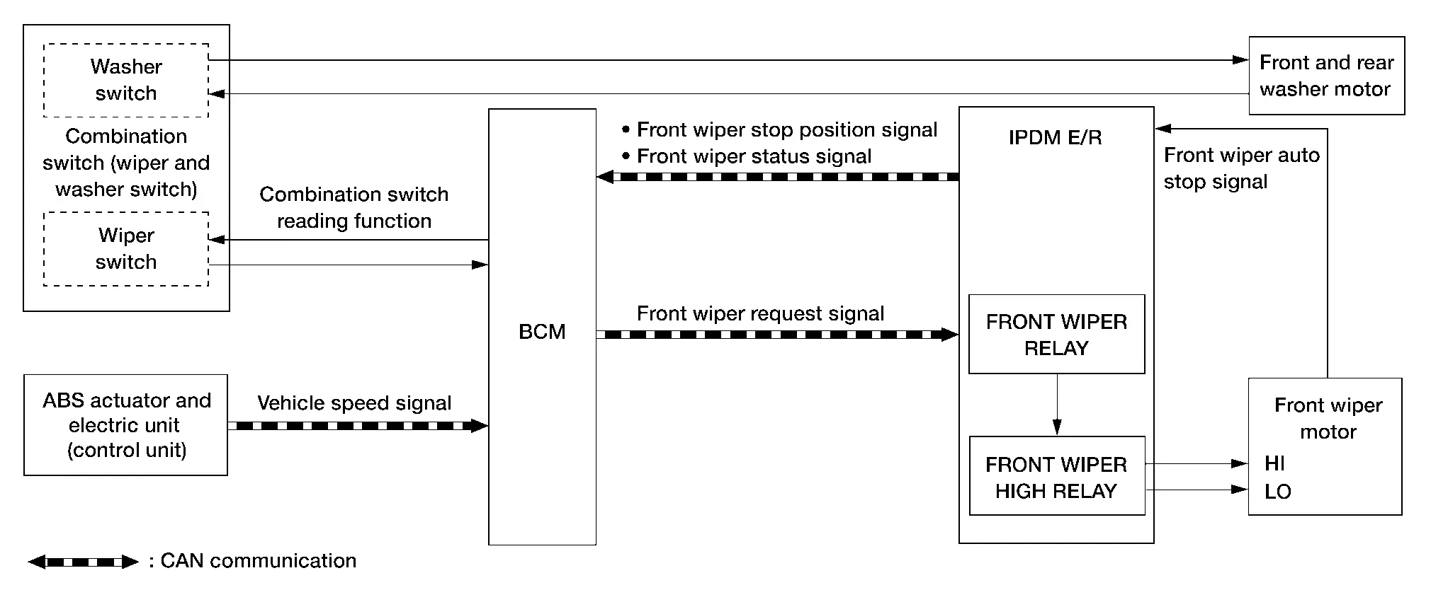
System Description (Without Rain Sensing Front Wipers)
SYSTEM DIAGRAM
| Component | Function |
|---|---|
| Front wiper motor | Refer to Front Wiper Motor. |
| IPDM E/R | Controls integrated relays according to the request from the BCM via CAN communication. |
| BCM |
|
| Combination switch (wiper and washer switch) | Transmits the status of the combination switch (wiper and washer) to the BCM. |
| ABS actuator and electric unit (control unit) | Transmits Nissan Pathfinder vehicle speed signal to the BCM via CAN communication. |
| Front and rear washer motor | Refer to Front and Rear Washer Motor. |
OUTLINE
The front wiper is controlled by each function of BCM and IPDM E/R.
Control by BCM:
-
Combination switch reading function
-
Front wiper control function
Control by IPDM E/R:
-
Front wiper control function
-
Relay control function
Combination meter indicates low washer fluid warning judged with the signal from the washer fluid level switch. For details of low washer fluid warning, refer to System Description.
Signal transmission function list
| Signal name | Input | Output | Description |
|---|---|---|---|
| Combination switch signal | Combination switch (wiper and washer switch) | BCM | Inputs the combination switch signal to the BCM. |
| Nissan Pathfinder Vehicle speed signal | ABS actuator and electric unit (control unit) | BCM (CAN) | Transmits the Nissan Pathfinder vehicle speed signal via CAN communication. |
| Front wiper request signal | BCM | IPDM E/R (CAN) | Transmits the front wiper request signal via CAN communication. |
| Front wiper stop position signal | IPDM E/R | BCM (CAN) | Transmits the front wiper stop position signal via CAN communication. |
| Front wiper status signal | IPDM E/R | BCM (CAN) | Transmits the front wiper status signal via CAN communication. |
| Front wiper auto stop signal | Front wiper motor | IPDM E/R | Transmits the front wiper auto stop signal to the IPDM E/R. |
FRONT WIPER BASIC OPERATION
-
BCM detects the combination switch (wiper and washer switch) condition by the combination switch reading function.
-
BCM transmits the front wiper request signal to the IPDM E/R via CAN communication depending on each operating condition of the front wiper.
-
IPDM E/R turns ON/OFF the integrated front wiper relay and the front wiper HIGH relay according to the front wiper request signal. IPDM E/R provides the power supply to operate the front wiper HI/LO operation.
FRONT WIPER LO OPERATION
-
BCM transmits the front wiper request signal (LOW) to the IPDM E/R via CAN communication according to the front wiper LO operating condition.
Front wiper LO operating condition:
-
Ignition switch ON
-
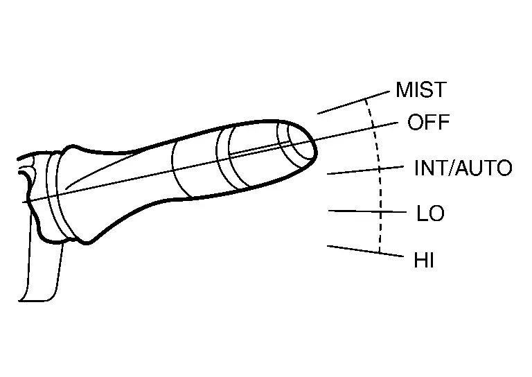
Front wiper switch LO or front wiper switch MIST (while pressing)
-
-
IPDM E/R turns ON the integrated front wiper relay according to the front wiper request signal (LOW).
FRONT WIPER HI OPERATION
-
BCM transmits the front wiper request signal (HIGH) to the IPDM E/R via CAN communication according to the front wiper HI operating condition.
Front wiper HI operating condition:
-
Ignition switch ON
-
Front wiper switch HI
-
-
IPDM E/R turns ON the integrated front wiper relay and the front wiper HIGH relay according to the front wiper request signal (HIGH).
FRONT WIPER INT OPERATION
-
BCM transmits the front wiper request signal (LOW) to the IPDM E/R via CAN communication depending on the front wiper INT operating condition and intermittent operation delay interval according to the wiper volume dial position.
Front wiper INT operating condition:
-
Ignition switch ON
-
Front wiper switch INT
-
-
IPDM E/R turns ON the integrated front wiper relay so that the front wiper is operated only once according to the front wiper request signal (LOW) and front wiper request signal (RETURN).
-
BCM detects stop position/except stop position of the front wiper motor according to the front wiper stop position signal received from the IPDM E/R via CAN communication.
-
BCM transmits the front wiper request signal (LOW) again after the intermittent operation delay interval.
 NOTE:
NOTE:
The front wiper INT operation setting of the linked or not linked with Nissan Pathfinder vehicle speed can be changed by combination meter setting.
Front wiper intermittent operation with vehicle speed:
-
BCM calculates the intermittent operation delay interval from the following:
-
Nissan Pathfinder Vehicle speed signal
-
Wiper volume dial position
-
Unit: Second
| Intermittent operation interval | Nissan Pathfinder Vehicle speed | |||||
| Accelerating |
0 – 18.6 MPH (0 – 30 km/h) |
18.7 – 37.3 MPH (31 – 60 km/h) |
37.4 – 65.2 MPH (61 – 105 km/h) |
65.3 MPH or more (106 km/h) |
||
| Decelerating |
0 – 16.5 MPH (0 – 25 km/h) |
16.6 – 34.2 MPH (26 – 55 km/h) |
34.3 – 62.1 MPH (56 – 100 km/h) |
62.2 MPH or more (101 km/h) |
||
|
Long ↑ ↓ Short |
Wiper volume dial position | 1 | 21.0* | 18.9 | 15.8 | 12.6 |
| 2 | 11.2* | 10.1 | 8.4 | 6.7 | ||
| 3 | 5.6* | 5.0 | 4.2 | 3.4 | ||
| 4 | 2.8* | 2.5 | 2.1 | 1.7 | ||
| 5 | 1.4* | 1.3 | 1.1 | 0.8 | ||
*: When operation setting is not linked with vehicle speed.
FRONT WIPER AUTO STOP OPERATION
-
BCM transmits the front wiper request signal (RETURN) to the IPDM E/R via CAN communication when the front wiper switch is turned OFF.
-
IPDM E/R detects the front wiper auto stop position signal from the front wiper motor to find out the front wiper motor position (stop position/except stop position).
-
When the IPDM E/R receives the front wiper request signal (RETURN) from the BCM and the front wiper motor position is not in the stop position, the IPDM E/R turns ON the front wiper relay until the front wiper motor returns to the stop position.
-
When the front wiper motor returns to the stop position, the IPDM E/R transmits front wiper status signal to the BCM via CAN communication.
-
When the BCM receives front wiper status signal from the IPDM E/R, the BCM transmits the front wiper request signal (STOP) to the IPDM E/R via CAN communication.
FRONT WIPER OPERATION LINKED WITH WASHER
-
BCM transmits the front wiper request signal (LO) to the IPDM E/R via CAN communication according to the washer linked operating condition of the front wiper.
-
BCM transmits the front wiper request signal (LO) so that the front wiper operates approximately two times when the front washer switch OFF signal is detected.
Washer linked operating condition of front wiper:
-
Ignition switch ON
-
Front washer switch ON (0.4 seconds or more)
-
-
IPDM E/R turns ON the integrated front wiper relay according to the front wiper request signal (LO).
-
The washer pump is supplied power and ground through the combination switch (wiper and washer switch) with the front washer switch ON.
WIPER LINKED AUTO LIGHTING FUNCTION
When lighting switch is in the AUTO position, front wiper operates, and then headlamp ON. Refer to System Description.
FRONT WIPER SERVICE POSITION OPERATION
When this operation is activated, front wiper operates at LO speed and stops in the service position so that front wiper arms can pulled up without contacting the hood.
Following 2 methods are the operation procedures.
Method A: With Ignition Switch ON
-
Ignition switch ON.
-
Confirm the vehicle is stopped.
-
Confirm front wiper is in stop position.
-
Quickly (within 0.5 seconds) move wiper switch lever to MIST position twice, wiper will move to service position.
-
To exit service position, operate front wiper switch.
Method B: With Ignition Switch OFF
-
Ignition switch OFF.
-
Confirm front wiper is in stop position.
-
Within 1 minute after placing ignition switch OFF, quickly (within 0.5 seconds) move wiper switch lever to MIST position twice, wiper will move to service position.

-
To exit service position, place ignition switch ON and operate front wiper switch.
 NOTE:
NOTE:
Front wiper arms can exit from service position without placing ignition switch ON if front wiper switch is operated within 1 minute after placing ignition switch OFF.
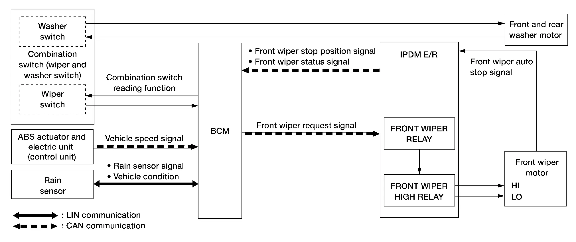
System Description (With Rain Sensing Front Wipers)
SYSTEM DIAGRAM
| Component | Function |
|---|---|
| Front wiper motor | Refer to Front Wiper Motor. |
| IPDM E/R | Controls integrated relays according to the request from the BCM via CAN communication. |
| BCM |
|
| Combination switch (wiper and washer switch) | Transmits the status of the combination switch (wiper and washer) to the BCM. |
| ABS actuator and electric unit (control unit) | Transmits Nissan Pathfinder vehicle speed signal to the BCM via CAN communication. |
| Front and rear washer motor | Refer to Front and Rear Washer Motor. |
| Rain sensor | Transmits the rain sensor signal to the BCM via LIN communication. |
OUTLINE
The front wiper is controlled by each function of BCM and IPDM E/R.
Control by BCM:
-
Combination switch reading function
-
Front wiper control function
-
Rain sensing wiper function
Control by IPDM E/R:
-
Front wiper control function
-
Relay control function
Combination meter indicates low washer fluid warning judged with the signal from the washer fluid level switch. For details of low washer fluid warning, refer to System Description.
Signal transmission function list
| Signal name | Input | Output | Description |
|---|---|---|---|
| Combination switch signal | Combination switch (wiper and washer switch) | BCM | Inputs the combination switch signal to the BCM. |
| Nissan Pathfinder Vehicle speed signal | ABS actuator and electric unit (control unit) | BCM (CAN) | Transmits the Nissan Pathfinder vehicle speed signal via CAN communication. |
| Front wiper request signal | BCM | IPDM E/R (CAN) | Transmits the front wiper request signal via CAN communication. |
| Front wiper stop position signal | IPDM E/R | BCM (CAN) | Transmits the front wiper stop position signal via CAN communication. |
| Front wiper status signal | IPDM E/R | BCM (CAN) | Transmits the front wiper status signal via CAN communication. |
| Front wiper auto stop signal | Front wiper motor | IPDM E/R | Transmits the front wiper auto stop signal to the IPDM E/R. |
| Rain sensor signal | Rain sensor | BCM (LIN) | Transmits the rain sensor signal to the BCM via LIN communication. |
| Nissan Pathfinder Vehicle condition | BCM | Rain sensor (LIN) | Transmits the Nissan Pathfinder vehicle condition to the rain sensor via LIN communication. |
FRONT WIPER BASIC OPERATION
-
BCM detects the combination switch (wiper and washer switch) condition by the combination switch reading function.
-
BCM transmits the front wiper request signal to the IPDM E/R via CAN communication depending on each operating condition of the front wiper.
-
IPDM E/R turns ON/OFF the integrated front wiper relay and the front wiper HIGH relay according to the front wiper request signal. IPDM E/R provides the power supply to operate the front wiper HI/LO operation.
FRONT WIPER LO OPERATION
-
BCM transmits the front wiper request signal (LOW) to the IPDM E/R via CAN communication according to the front wiper LO operating condition.
Front wiper LO operating condition:
-
Ignition switch ON
-
Front wiper switch LO or front wiper switch MIST (while pressing)
-
-
IPDM E/R turns ON the integrated front wiper relay according to the front wiper request signal (LOW).
FRONT WIPER HI OPERATION
-
BCM transmits the front wiper request signal (HIGH) to the IPDM E/R via CAN communication according to the front wiper HI operating condition.
Front wiper HI operating condition:
-
Ignition switch ON
-
Front wiper switch HI
-
-
IPDM E/R turns ON the integrated front wiper relay and the front wiper HIGH relay according to the front wiper request signal (HIGH).
FRONT WIPER INT OPERATION
-
BCM transmits the front wiper request signal (LOW) to the IPDM E/R via CAN communication depending on the front wiper INT operating condition and intermittent operation delay interval according to the wiper volume dial position.
Front wiper INT operating condition:
-
Ignition switch ON
-
Front wiper switch INT
-
-
IPDM E/R turns ON the integrated front wiper relay so that the front wiper is operated only once according to the front wiper request signal (LOW) and front wiper request signal (RETURN).
-
BCM detects stop position/except stop position of the front wiper motor according to the front wiper stop position signal received from the IPDM E/R via CAN communication.
-
BCM transmits the front wiper request signal (LOW) again after the intermittent operation delay interval.
 NOTE:
NOTE:
The front wiper INT operation setting of the linked or not linked with Nissan Pathfinder vehicle speed can be changed by combination meter setting.
Front wiper intermittent operation with vehicle speed:
-
BCM calculates the intermittent operation delay interval from the following:
-
Nissan Pathfinder Vehicle speed signal
-
Wiper volume dial position
-
Unit: Second
| Intermittent operation interval | Nissan Pathfinder Vehicle speed | |||||
| Accelerating |
0 – 18.6 MPH (0 – 30 km/h) |
18.7 – 37.3 MPH (31 – 60 km/h) |
37.4 – 65.2 MPH (61 – 105 km/h) |
65.3 MPH or more (106 km/h) |
||
| Decelerating |
0 – 16.5 MPH (0 – 25 km/h) |
16.6 – 34.2 MPH (26 – 55 km/h) |
34.3 – 62.1 MPH (56 – 100 km/h) |
62.2 MPH or more (101 km/h) |
||
|
Long ↑ ↓ Short |
Wiper volume dial position | 1 | 21.0* | 18.9 | 15.8 | 12.6 |
| 2 | 11.2* | 10.1 | 8.4 | 6.7 | ||
| 3 | 5.6* | 5.0 | 4.2 | 3.4 | ||
| 4 | 2.8* | 2.5 | 2.1 | 1.7 | ||
| 5 | 1.4* | 1.3 | 1.1 | 0.8 | ||
*: When operation setting is not linked with vehicle speed.
FRONT WIPER AUTO OPERATION
Rain Detection
Rain level and sensor conditions are detected by rain sensor.
-
BCM transmits the vehicle conditions (vehicle speed, front wiper condition, rain sensor sensitivity setting, etc.) to the rain sensor via LIN communication.
-
Rain sensor judges a wiping speed for front wiper by rain condition and the Nissan Pathfinder vehicle conditions. It transmits the wiping speed request signal to the BCM via LIN communication.
Auto Wiping Operation
-
BCM receives the wiping speed request signal from the rain sensor via LIN communication.
-
BCM controls front wiper operation according to the wiping speed request signals. It transmits the front wiper request signals (LO or HI) to the IPDM E/R via CAN communication.
Front wiper AUTO operating condition:
-
Ignition switch ON
-
Front wiper switch AUTO
-
 NOTE:
NOTE:
-
When the front wiper switch is turned to AUTO position, the front wiper operates once regardless of rainy conditions.
-
Factory setting of the front wiper AUTO operation is operation linked with rain sensor. Front wiper AUTO operation can be set to operation linked or not linked with rain sensor using CONSULT. Refer to CONSULT Function (BCM - WIPER).
Rain Sensor Sensitivity Setting
BCM determines rain sensor sensitivity according to wiper volume dial position.
| Wiper volume dial position | Sensitivity |
|---|---|
| 1 | High sensitivity |
| 2 | Medium−high sensitivity |
| 3 | Low−medium sensitivity |
| 4 | Low sensitivity |
 NOTE:
NOTE:
When the wiper volume dial position is turned up by 1 level under front wiper AUTO operating condition, the front wiper operates once.
Splash mode operation
The front wiper is operated at HI regardless of the wiper volume adjustment position when water drops are instantaneously sprayed over the windshield glass due to water splash from oncoming Nissan Pathfinder vehicles or other causes. After that, AUTO operation is performed depending on the amount of water drops.
SPLASH MODE OPERATION CONDITIONS:
-
Front wiper switch AUTO
-
Ignition switch ON
 NOTE:
NOTE:
Splash mode is not operated and auto wiping operation is performed while the Nissan Pathfinder vehicle is stopped.
FRONT WIPER AUTO STOP OPERATION
-
BCM transmits the front wiper request signal (RETURN) to the IPDM E/R via CAN communication when the front wiper switch is turned OFF.
-
IPDM E/R detects the front wiper auto stop position signal from the front wiper motor to find out the front wiper motor position (stop position/except stop position).
-
When the IPDM E/R receives the front wiper request signal (RETURN) from the BCM and the front wiper motor position is not in the stop position, the IPDM E/R turns ON the front wiper relay until the front wiper motor returns to the stop position.
-
When the front wiper motor returns to the stop position, the IPDM E/R transmits front wiper status signal to the BCM via CAN communication.
-
When the BCM receives front wiper status signal from the IPDM E/R, the BCM transmits the front wiper request signal (STOP) to the IPDM E/R via CAN communication.
FRONT WIPER OPERATION LINKED WITH WASHER
-
BCM transmits the front wiper request signal (LO) to the IPDM E/R via CAN communication according to the washer linked operating condition of the front wiper.
-
BCM transmits the front wiper request signal (LO) so that the front wiper operates approximately two times when the front washer switch OFF signal is detected.
Washer linked operating condition of front wiper:
-
Ignition switch ON
-
Front washer switch ON (0.4 seconds or more)
-
-
IPDM E/R turns ON the integrated front wiper relay according to the front wiper request signal (LO).
-
The washer pump is supplied power and ground through the combination switch (wiper and washer switch) with the front washer switch ON.
WIPER LINKED AUTO LIGHTING FUNCTION
When lighting switch is in the AUTO position, front wiper operates, and then headlamp ON. Refer to System Description.
FRONT WIPER SERVICE POSITION OPERATION
When this operation is activated, front wiper operates at LO speed and stops in the service position so that front wiper arms can pulled up without contacting the hood.
Following 2 methods are the operation procedures.
Method A: With Ignition Switch ON
-
Ignition switch ON.
-
Confirm the vehicle is stopped.
-
Confirm front wiper is in stop position.
-
Quickly (within 0.5 seconds) move wiper switch lever to MIST position twice, wiper will move to service position.

-
To exit service position, operate front wiper switch.
Method B: With Ignition Switch OFF
-
Ignition switch OFF.
-
Confirm front wiper is in stop position.
-
Within 1 minute after placing ignition switch OFF, quickly (within 0.5 seconds) move wiper switch lever to MIST position twice, wiper will move to service position.

-
To exit service position, place ignition switch ON and operate front wiper switch.
 NOTE:
NOTE:
Front wiper arms can exit from service position without placing ignition switch ON if front wiper switch is operated within 1 minute after placing ignition switch OFF.
Rear Wiper and Washer System Nissan Pathfinder 5th Gen
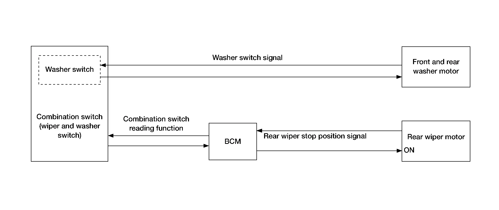
System Description
SYSTEM DIAGRAM
| Component | Function |
|---|---|
| Rear wiper motor | Refer to Rear Wiper Motor. |
| BCM | Supplies power to the rear wiper motor |
| Combination switch (wiper and washer switch) | Transmits the status of the combination switch (wiper and washer) to the BCM. |
| Front and rear washer motor | Refer to Front and Rear Washer Motor. |
OUTLINE
The rear wiper is controlled by each function of BCM.
Control by BCM:
-
Combination switch reading function
-
Rear wiper control function
Signal transmission function list
| Signal name | Input | Output | Description |
|---|---|---|---|
| Washer switch signal | Combination switch (wiper and washer switch) | Front and rear washer motor | Washer switch signal activates/deactivates the front and rear washer motor. |
| Combination switch signal | Combination switch (wiper and washer switch) | BCM | Transmits the combination switch signal to the BCM. |
| Rear wiper stop position signal | Rear wiper motor | BCM | Transmits the rear wiper stop position signal to the BCM. |
REAR WIPER BASIC OPERATION
-
BCM detects the combination switch (wiper and washer switch) condition by the combination switch reading function.
-
BCM controls the rear wiper to start or stop.
REAR WIPER ON OPERATION
-
BCM supplies power to the rear wiper motor according to the rear wiper ON operating condition.
Rear wiper ON operating condition:
-
Ignition switch ON
-
Rear wiper switch ON
-
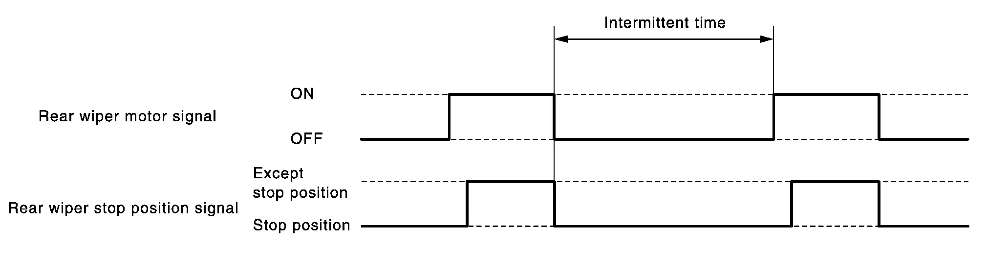
REAR WIPER INT OPERATION
-
BCM supplies power to the rear wiper motor according to the INT operating condition.
Rear wiper INT operating condition:
-
Ignition switch ON
-
Rear wiper switch INT
-
-
BCM controls the rear wiper to operate once.
-
BCM detects the rear wiper motor stop position.
-
BCM supplies power to the rear wiper motor after an intermittent from the stop of the rear wiper motor.
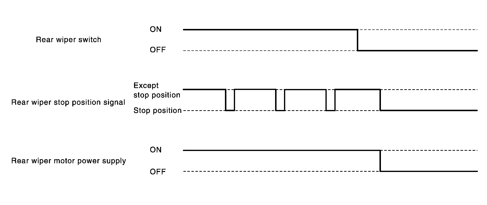
REAR WIPER AUTO STOP OPERATION
-
BCM stops supplying power to the rear wiper motor when the rear wiper switch is turned OFF.
-
BCM reads a rear wiper stop position signal from the rear wiper motor to detect a rear wiper motor position.
-
When the rear wiper motor is at other than the stopping position, BCM continues to supply power to the rear wiper motor until it returns to the stop position.
 NOTE:
NOTE:
BCM stops supplying power to the rear wiper motor when the ignition switch is placed OFF.
REAR WIPER OPERATION LINKED WITH WASHER
-
BCM supplies power to the rear wiper motor according to the washer linked operating condition of rear wiper. When the rear washer switch is turned OFF, BCM controls rear wiper to operate approximately 3 times.
Washer linked operating condition of rear wiper:
-
Ignition switch ON
-
Rear washer switch ON
-
-
The front and rear washer motor is supplied power and ground through the combination switch (wiper and washer switch) with the rear washer switch ON.
REAR WIPER OPERATION LINKED WITH REVERSE
-
BCM controls rear wiper to INT operating according to the conditions of rear wiper operation linked with reverse.
Condition of rear wiper operation linked with reverse:
-
Ignition switch ON
-
Front wiper switch: LO, HI, INT or AUTO
-
Rear wiper switch OFF
-
Shift lever “R”
-
-
When shift lever is shifted to “R”, TCM transmits reverse switch signal to BCM via CAN communication, and then operates rear wiper motor.
 NOTE:
NOTE:
Rear wiper operation linked with reverse can be set to ON or OFF changed by combination meter setting.
Washer Fluid Warning System Nissan Pathfinder SUV
System Description
SYSTEM DIAGRAM
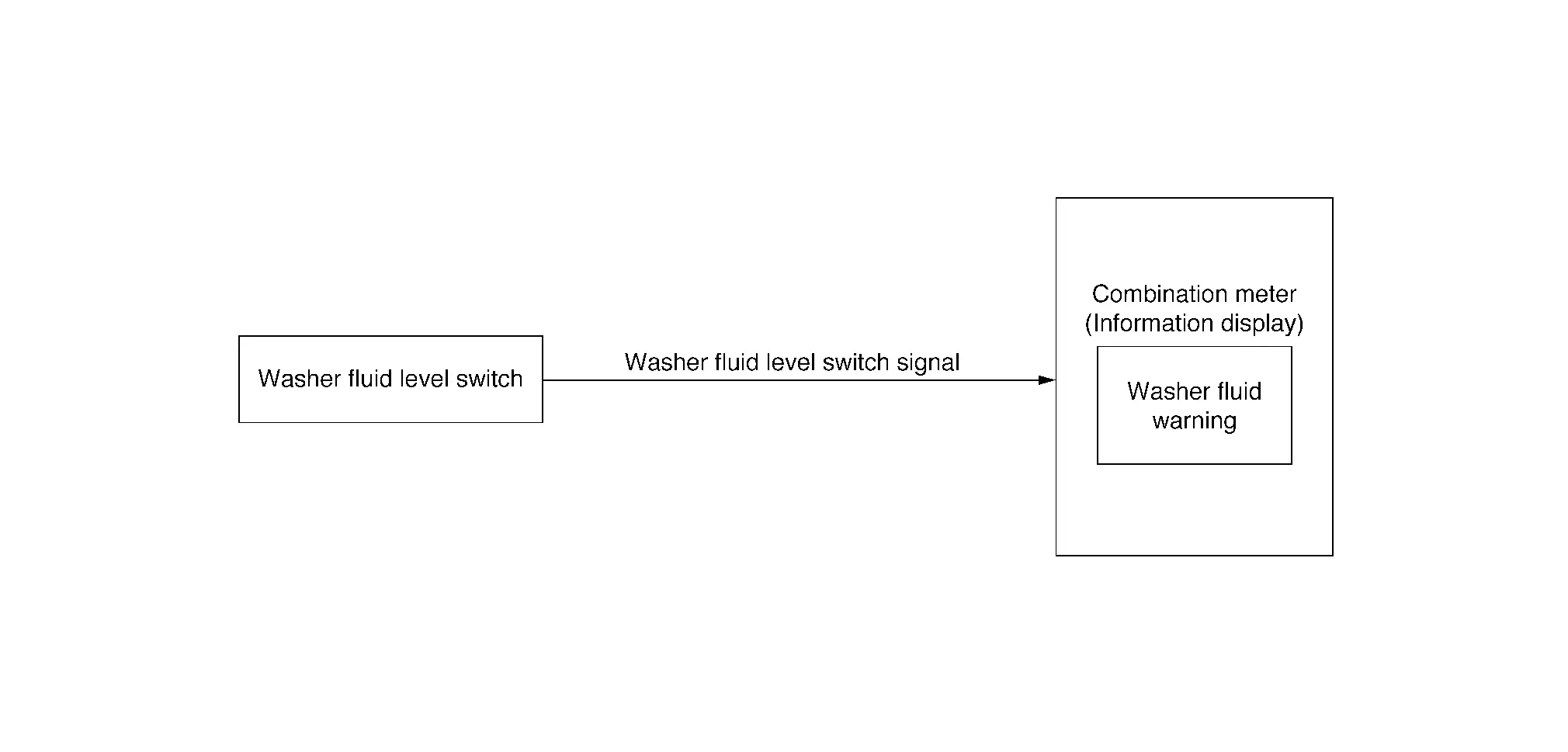
| Component | Function |
|---|---|
| Washer fluid level switch | Refer to Washer Fluid Level Switch. |
| Combination meter | The combination meter displays the washer fluid warning according to the washer fluid level switch input. |
Signal transmission function list
| Signal name | Input | Output | Description |
|---|---|---|---|
| Washer fluid level switch signal | Washer fluid level switch | Combination meter | Transmits the washer fluid level switch signal to the combination meter. |
DESIGN/PURPOSE
Washer fluid warning reminds the driver that the washer fluid level is insufficient.
| Symbol | Message |
|---|---|
|
|
Low Washer Fluid |

SYNCHRONIZATION WITH MASTER WARNING LAMP
Not applicable
SIGNAL PATH
-
When washer fluid level is low, the washer fluid level switch turns ON and transmits the washer fluid level switch signal to the combination meter.
-
The combination meter displays washer fluid warning according to washer fluid level switch signal.
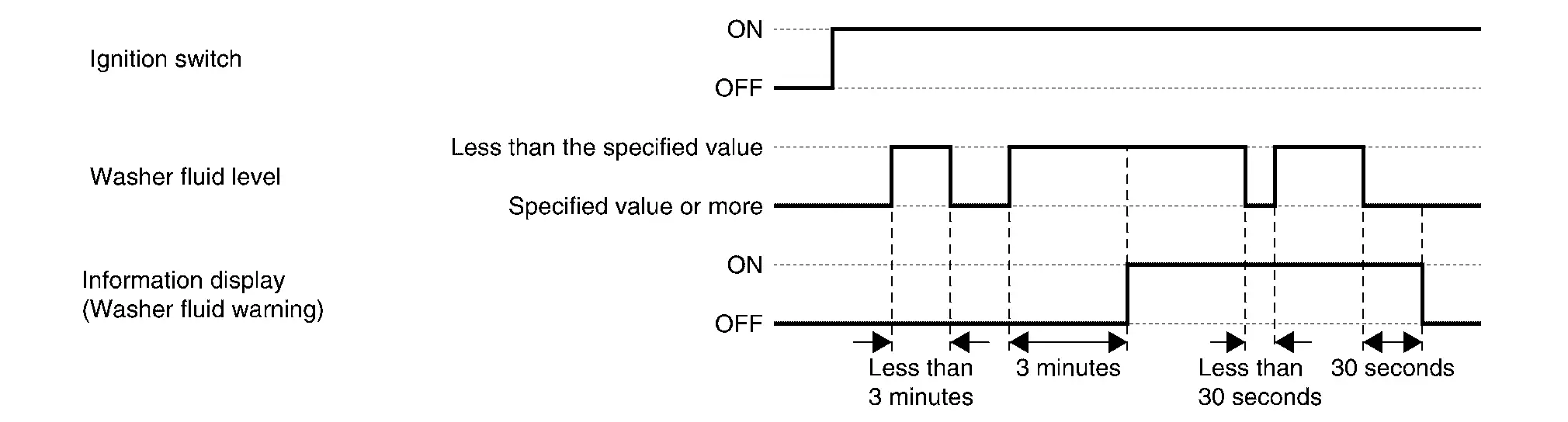
WARNING/INDICATOR OPERATING CONDITION
When all of the conditions listed below are satisfied:
-
Ignition switch is ON.
-
Washer fluid level is insufficient. (Washer fluid level switch is ON and 3 minutes have passed.)
WARNING/INDICATOR CANCEL CONDITION
When any of the conditions listed below are satisfied:
-
Ignition switch is OFF.
-
After refill the washer fluid. (Washer fluid level switch is OFF and 30 seconds have passed.)
TIMING CHART

Nissan Pathfinder (R53) 2022-2026 Service Manual
System
Contact Us
Nissan Pathfinder Info Center
Email: info@nipathfinder.com
Phone: +1 (800) 123-4567
Address: 123 Pathfinder Blvd, Nashville, TN 37214, USA
Working Hours: Mon–Fri, 9:00 AM – 5:00 PM (EST)
