Nissan Pathfinder: Security Control System - System
- Intelligent Key System/engine Start Function
- Nissan Vehicle Immobilizer System
- Vehicle Security System
- Information Display (combination Meter)
Intelligent Key System/engine Start Function Nissan Pathfinder 2026
System Description
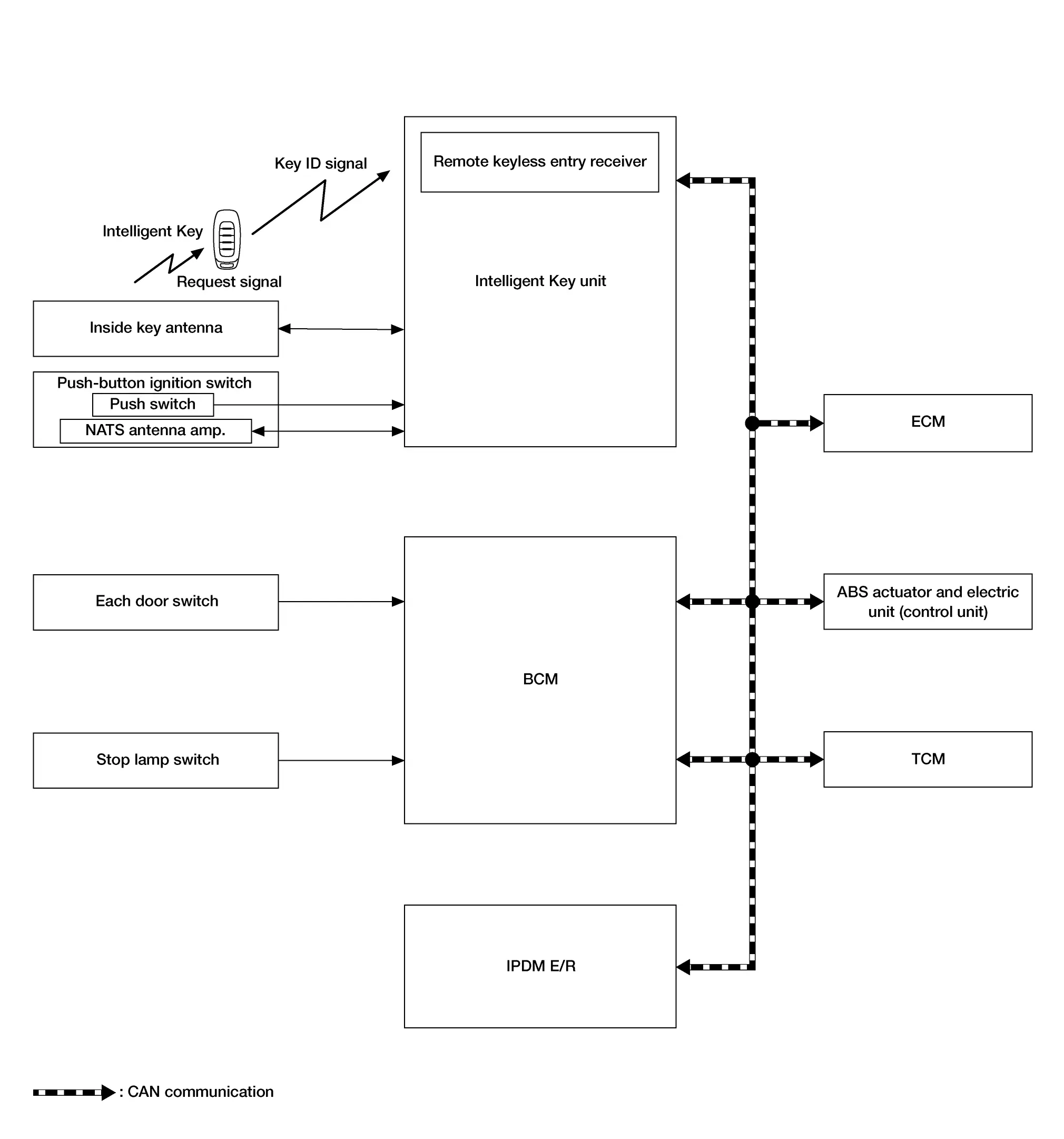
SYSTEM DIAGRAM
| Component | Function | |
|---|---|---|
| Door switch | Door switch detects door switch condition and then transmits door switch signal to BCM. | |
| Inside key antenna | Inside key antenna detects whether Intelligent Key is inside the Nissan Pathfinder vehicle, and transmits the key ID signal to Intelligent Key unit. | |
| Stop lamp switch | Stop lamp switch detects that brake pedal is depressed, and then transmits stop lamp switch signal to BCM. | |
| ABS actuator and electric unit (control unit) | ABS actuator and electric unit (control unit) transmits the Nissan Pathfinder vehicle speed signal to BCM via CAN communication. | |
| TCM | TCM receives the P/N position signal from transmission range switch, and then transmits the shift position signal to BCM via CAN communication. | |
| ECM |
|
|
| IPDM E/R | Starter cut relay is controlled by BCM, and starter relay is controlled by IPDM E/R while communicating with BCM. | |
| BCM | When BCM receives a starter cut relay request signal from ECM, the starter cut relay is turned ON. | |
| Push-button ignition switch | Push switch |
|
| NATS antenna amp. |
|
|
| Intelligent Key | The Intelligent Key system is a system that makes it possible to lock and unlock the door locks (door lock/unlock function) by carrying the Intelligent Key, which operates based on the results of electronic ID verification using two-way communication between the Intelligent Key and the Nissan Pathfinder vehicle (Intelligent Key unit). | |
| Intelligent Key unit |
|
|
| TCU | TCU transmits engine start request signal to BCM when engine start request is received from Infiniti ConnectionTM data center. | |
BCM INPUT/OUTPUT SIGNAL CHART
Input Signal Item
| Transmit unit | Signal name | |
|---|---|---|
| ECM | CAN communication |
|
| IPDM E/R |
|
|
| ABS actuator and electric unit (control unit) | Nissan Pathfinder Vehicle speed signal | |
| TCM | Shift position signal | |
| TCU | Engine start request signal | |
| Each door switch | Door switch signal | |
| Stop lamp switch | Stop lamp switch signal | |
Output Signal Item
| Reception unit | Signal name | |
|---|---|---|
| IPDM E/R | CAN communication | Ignition ON signal |
INTELLIGENT KEY UNIT INPUT/OUTPUT SIGNAL CHART
Input Signal Item
| Transmit unit | Signal name | |
|---|---|---|
| IPDM E/R | CAN communication | Ignition ON signal |
Output Signal Item
| Reception unit | Signal name | |
|---|---|---|
| IPDM E/R | CAN communication | Ignition ON signal |
| Inside key antenna | Key ID request signal | |
SYSTEM DESCRIPTION
-
The engine start function of Intelligent Key system makes it possible to start and stop the engine without using the key, based on the electronic ID verification. The electronic ID verification is performed between Intelligent Key unit and Intelligent Key when the push-button ignition switch is pressed while the Intelligent Key is within the detection area of inside key antenna.
 NOTE:
NOTE:
The driver should carry the Intelligent Key at all times.
-
Intelligent Key have ID (Key ID). It can perform the door lock/unlock operation and the push-button ignition switch operation when the registered Intelligent Key is carried.
-
If the ID is successfully verified, when push-button ignition switch is pressed, engine can be started.
-
Up to 4 Intelligent Keys can be registered (Including the standard Intelligent Key) upon request from the customer.
 NOTE:
NOTE:
For any functions other than engine start function of Intelligent Key system. Refer to System Description.
PRECAUTIONS FOR INTELLIGENT KEY SYSTEM
The transponder (the chip for NATS ID verification) is integrated into the Intelligent Key. It is integrated into the mechanical key. Therefore, ID verification cannot be performed by mechanical key only.
In that case, NATS ID verification can be performed when Intelligent Key backside is contacted to push-button ignition switch while brake pedal is depressed. If verification result is OK, engine can be started.
OPERATION WHEN INTELLIGENT KEY IS CARRIED
-
When the push-button ignition switch is pressed, the Intelligent Key unit activates the inside key antenna and transmits the request signal to the Intelligent Key.
-
The Intelligent Key receives the request signal and transmits the NATS ID signal to the Intelligent Key unit.
-
Intelligent Key unit receives the NATS ID signal verifies it with the registered ID.
-
When the ignition switch is placed to ON, Intelligent Key unit performs ID verification with the ECM. When the result is OK, engine start is permitted.
-
When ECM detects that the start engine conditions* are satisfied, it transmits a starter cut relay request signal to BCM.
-
When BCM receives a starter cut relay request signal from ECM, the starter cut relay is turned ON.
-
When starter cut relay is turned ON, IPDM E/R turns ON the starter relay and drives the starter motor.
-
When BCM receives an engine status signal from ECM, it turns the starter relay and starter cut relay OFF and stops cranking.
CAUTION:
When the Intelligent Key is carried outside of the Nissan Pathfinder vehicle (outside key antenna detection area) while the power supply is in the ON position, even if the engine start condition* is satisfied, the engine cannot be started.
*: For the engine start condition, refer to “IGNITION SWITCH POSITION CHANGE TABLE BY PUSH-BUTTON IGNITION SWITCH OPERATION”.
OPERATION RANGE
Engine can be started when Intelligent Key is inside the vehicle. However, sometimes engine may not start when Intelligent Key is on instrument panel or in glove box.
IGNITION SWITCH POSITION CHANGE TABLE BY PUSH-BUTTON IGNITION SWITCH OPERATION
The ignition switch position can be changed by the following operations.
 NOTE:
NOTE:
-
When an Intelligent Key is within the detection area of inside key antenna or when Intelligent Key backside is contacted to push-button ignition switch, it is equivalent to the operations below.
-
When starting the engine, the BCM monitors under the engine start conditions.
-
Brake pedal operation condition
-
Selector lever position
-
Nissan Pathfinder Vehicle speed
-
Vehicle speed: less than 4 km/h (2.5 MPH)
| Power supply position | Condition | Push-button ignition switch operation frequency | |
|---|---|---|---|
| Selector lever | Brake pedal operation condition | ||
| OFF → ON | — | Not depressed | 1 |
| OFF → ON → OFF | — | Not depressed | 2 |
|
OFF → START ON → START |
P or N position | Depressed | 1 |
| Engine is running → OFF | — | — | 1 |
 NOTE:
NOTE:
If the Intelligent Key unit cannot detect that the Intelligent Key is in the Nissan Pathfinder vehicle, ignition switch can be placed OFF by the press and hold the push-button ignition switch for 2 seconds or more.
Vehicle speed: 4 km/h (2.5 MPH) or more
| Power supply position | Condition | Push-button ignition switch operation frequency | |
|---|---|---|---|
| Selector lever | Brake pedal operation condition | ||
| Engine is running → OFF | — | — | Emergency stop operation |
| Engine stall return operation while driving | N position | Not depressed | 1 |
Emergency stop operation
-
Press and hold the push-button ignition switch for 2 seconds or more.
-
Press the push-button ignition switch 3 times or more within 1.5 seconds.
REMOTE ENGINE START FUNCTION
Remote engine start function enables engine to be started from vehicle outside by operating remote engine start button of Intelligent Key or cellular phone.
In the same way as the Intelligent Key, the engine can be started by operating a cellular phone using the Telematics system function.
Engine Start Procedures
The following operation enables the engine to be started:
-
Press LOCK button of Intelligent Key, and then within 5 seconds, press and hold remote engine start button of Intelligent Key for 2 seconds or more.
-
Perform engine start operation using a cellular phone.
Engine does not start while the vehicle is in the following status:
-
All doors are UNLOCKED or any door is open.
-
Hood is open.
-
A registered Intelligent Key is in passenger room.
-
Shift position is other than P.
-
Nissan Pathfinder Vehicle security alarm is in operation.
-
Hazard lamp is in operation.
Engine Stop Procedures
The following operation enables the engine to be stopped:
-
Press remote engine start button of Intelligent Key.
-
Perform engine stop operation using a cellular phone.
-
Push-button ignition switch is operated.
Engine stops when the vehicle status changes to the following status:
-
10 minutes are passed since engine start.
-
Hood is open.
-
Shift position is shifted to a position other than P.
-
Nissan Pathfinder Vehicle security alarm starts to operate.
 NOTE:
NOTE:
While engine is in operation by Intelligent Key, engine operation time can be extended for 10 minutes. To extend engine operation time, press LOCK button of Intelligent Key, and then within 5 seconds, press and hold remote engine start button of Intelligent Key for 2 seconds or more.
Operation Area
The engine can be started when the vehicle is under the following conditions.
-
The remote engine start operating range is approximately 60 m (197 ft.) from the vehicle.
-
The Nissan Pathfinder vehicle is within the communication range of the NissanConnect™ data center.
Nissan Vehicle Immobilizer System Nissan Pathfinder 2026
System Description
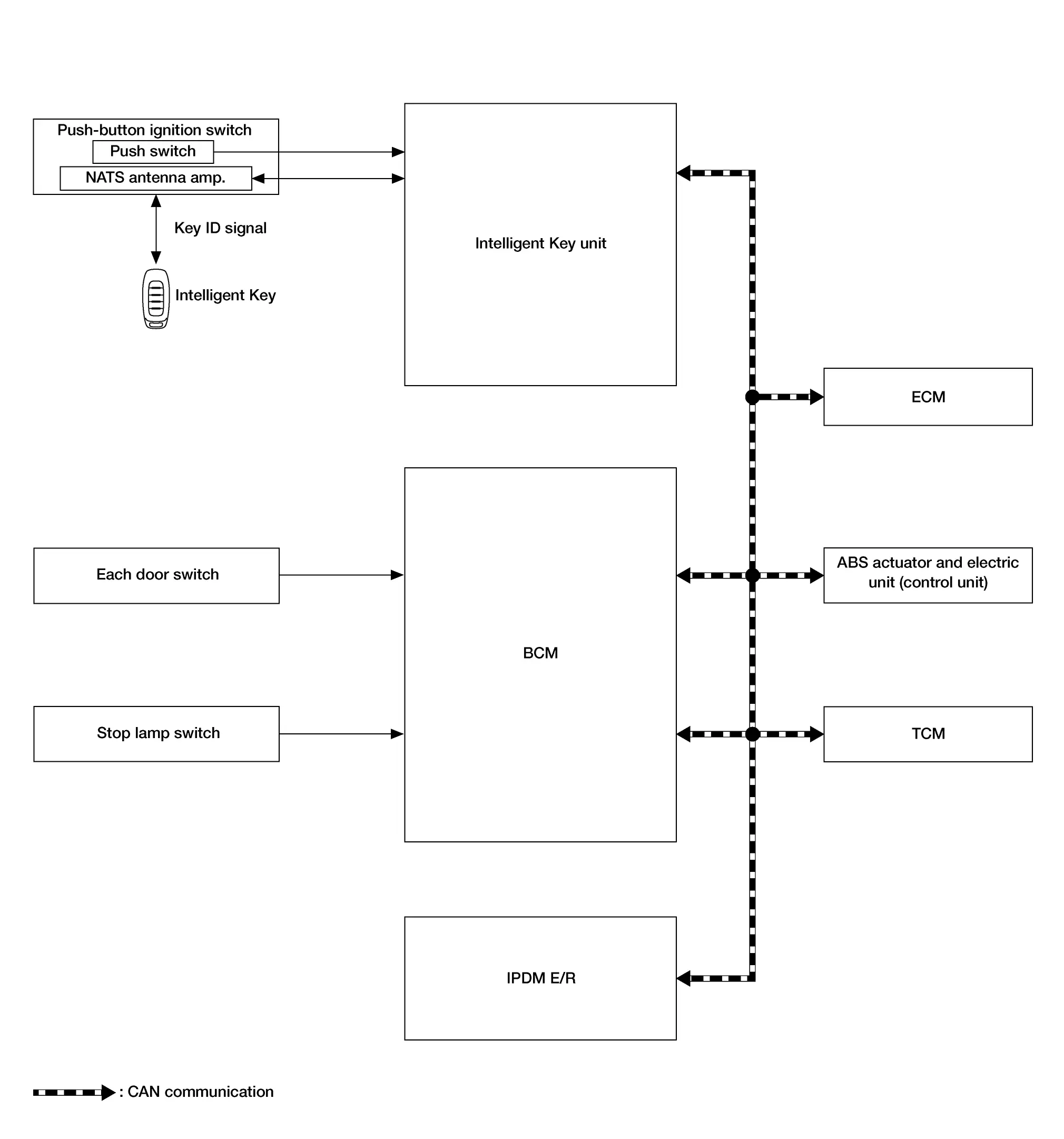
SYSTEM DIAGRAM
| Component | Function | |
|---|---|---|
| Door switch | Door switch detects door switch condition and then transmits door switch signal to BCM. | |
| Stop lamp switch | Stop lamp switch detects that brake pedal is depressed, and then transmits stop lamp switch signal to BCM. | |
| ABS actuator and electric unit (control unit) | ABS actuator and electric unit (control unit) transmits the Nissan Pathfinder vehicle speed signal to BCM via CAN communication. | |
| TCM | TCM receives the P/N position signal from transmission range switch, and then transmits the shift position signal to BCM via CAN communication. | |
| ECM |
|
|
| IPDM E/R | Starter cut relay is controlled by BCM, and starter relay is controlled by IPDM E/R while communicating with BCM. | |
| BCM | When BCM receives a starter cut relay request signal from ECM, the starter cut relay is turned ON. | |
| Push-button ignition switch | Push switch |
|
| NATS antenna amp. | Refer to NATS Antenna Amp. | |
| Intelligent Key | The Intelligent Key system is a system that makes it possible to lock and unlock the door locks (door lock/ unlock function) by carrying the Intelligent Key, which operates based on the results of electronic ID verification using two-way communication between the Intelligent Key and the Nissan Pathfinder vehicle (Intelligent Key unit). | |
| Intelligent Key unit |
|
|
BCM INPUT/OUTPUT SIGNAL CHART
Input Signal Item
| Transmit unit | Signal name | |
|---|---|---|
| ECM | CAN communication |
|
| IPDM E/R |
|
|
| ABS actuator and electric unit (control unit) | Nissan Pathfinder Vehicle speed signal | |
| TCM | Shift position signal | |
| Each door switch | Door switch signal | |
| Stop lamp switch | Stop lamp switch signal | |
Output Signal Item
| Reception unit | Signal name | |
|---|---|---|
| IPDM E/R | CAN communication | Ignition ON signal |
INTELLIGENT KEY UNIT INPUT/OUTPUT SIGNAL CHART
Input Signal Item
| Transmit unit | Signal name | |
|---|---|---|
| IPDM E/R | CAN communication | Ignition ON signal |
| NATS antenna amp. | Key ID signal | |
Output Signal Item
| Reception unit | Signal name | |
|---|---|---|
| IPDM E/R | CAN communication | Ignition ON signal |
| Inside key antenna | Key ID request signal | |
SYSTEM DESCRIPTION
-
The NISSAN VEHICLE IMMOBILIZER SYSTEM (NVIS) prevents the engine from being started by Intelligent Key whose ID is not registered to the Nissan Pathfinder vehicle (Intelligent Key unit). It has higher protection against auto theft involving the duplication of mechanical keys.
-
The ignition key integrated in the Intelligent Key cannot start the engine. When the Intelligent Key battery is discharged, the NATS ID verification is performed between the transponder integrated with Intelligent Key and Intelligent Key unit via NATS antenna amp. when the Intelligent Key backside is contacted to push-button ignition switch while brake pedal is depressed. If the verification result is OK, the engine start operation can be performed by the push-button ignition switch operation.
-
Up to 4 Intelligent Keys can be registered (including the standard ignition key) upon request from the owner.
-
When replacing ECM, Intelligent Key unit or Intelligent Key, the specified procedure (Initialization and registration) using CONSULT is required.
PRECAUTIONS FOR KEY REGISTRATION
The ID registration is a procedure that erases the current NATS ID once, and then registers a new ID. Therefore before starting the registration operation, collect all registered Intelligent Keys from the customer.
ENGINE START OPERATION WHEN INTELLIGENT KEY IS CONTACTED TO PUSH-BUTTON IGNITION SWITCH
-
When brake pedal is depressed while selector lever is in the P position, Intelligent Key unit activates NATS antenna amp. that is located behind push-button ignition switch.
-
When Intelligent Key (transponder built-in) backside is contacted to push-button ignition switch, Intelligent Key unit starts NATS ID verification between Intelligent Key unit and Intelligent Key (transponder built-in) via NATS antenna amp.
-
When the ignition switch is placed to ON, Intelligent Key unit performs ID verification with the ECM. When the result is OK, engine start is permitted.
-
BCM detects that the selector lever position and brake pedal operation condition.
-
When ECM detects that the start engine conditions* are satisfied, it transmits a starter cut relay request signal to BCM.
-
When BCM receives a starter cut relay request signal from ECM, the starter cut relay is turned ON.
-
When starter cut relay is turned ON, IPDM E/R turns ON the starter relay and drives the starter motor.
-
When BCM receives an engine status signal from ECM, it turns the starter relay and starter cut relay OFF and stops cranking.
*: For the engine start condition, refer to “IGNITION SWITCH POSITION CHANGE TABLE BY PUSH-BUTTON IGNITION SWITCH OPERATION” below.
IGNITION SWITCH POSITION CHANGE TABLE BY PUSH-BUTTON IGNITION SWITCH OPERATION
The ignition switch position can be changed by the following operations.
 NOTE:
NOTE:
-
When an Intelligent Key is within the detection area of inside key antenna or when Intelligent Key backside is contacted to push-button ignition switch, it is equivalent to the operations below.
-
When starting the engine, the BCM monitors under the engine start conditions.
-
Brake pedal operation condition
-
Selector lever position
-
Nissan Pathfinder Vehicle speed
-
Vehicle speed: less than 4 km/h (2.5 MPH)
| Power supply position | Condition | Push-button ignition switch operation frequency | |
|---|---|---|---|
| Selector lever | Brake pedal operation condition | ||
| OFF → ON | — | Not depressed | 1 |
| OFF → ON → OFF | — | Not depressed | 2 |
|
OFF → START ON → START |
P or N position | Depressed | 1 |
| Engine is running → OFF | — | — | 1 |
 NOTE:
NOTE:
If the Intelligent Key unit cannot detect that the Intelligent Key is in the Nissan Pathfinder vehicle, ignition switch can be placed OFF by pressing and holding the push-button ignition switch for 2 seconds or more.
Vehicle speed: 4 km/h (2.5 MPH) or more
| Power supply position | Condition | Push-button ignition switch operation frequency | |
|---|---|---|---|
| Selector lever | Brake pedal operation condition | ||
| Engine is running → OFF | — | — | Emergency stop operation |
| Engine stall return operation while driving | N position | Not depressed | 1 |
Emergency stop operation
-
Press and hold the push-button ignition switch for 2 seconds or more.
-
Press the push-button ignition switch 3 times or more within 1.5 seconds.
Vehicle Security System Nissan Pathfinder 2022
System Description
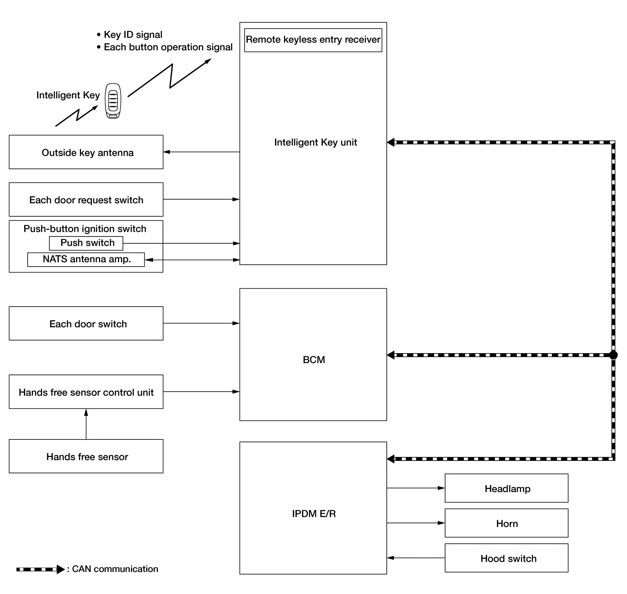
SYSTEM DIAGRAM
| Component | Function |
|---|---|
| Door switch | Door switch detects door open/close condition and then transmits door switch signal to BCM. |
| IPDM E/R |
|
| BCM |
|
| Push-button ignition switch |
|
| Intelligent Key | The Intelligent Key system is a system that makes it possible to lock and unlock the door locks (door lock/unlock function) by carrying the Intelligent Key, which operates based on the results of electronic ID verification using two-way communication between the Intelligent Key and the Nissan Pathfinder vehicle (Intelligent Key unit). |
| Outside key antenna | Outside key antenna detects whether Intelligent Key is within the detection area or not, and then transmits signal to Intelligent Key unit. |
| Door request switch | Door request switch transmits door lock/unlock request signal to Intelligent Key unit. |
| Hood switch | Refer to Hood Switch. |
| Horn |
|
| Intelligent Key unit | Intelligent Key unit performs the ID verification between Intelligent Key unit and Intelligent Key when the Intelligent Key is carried into the detection area of NATS antenna amp., and push-button ignition switch is pressed. If the ID verification result is OK, ignition switch operation is available. |
| Headlamp | Panic alarm function activates headlamps intermittently when operating a cellular phone using the Telematics system function. |
| Hands free sensor control unit | Hands free sensor control unit judges user operation by detecting the hands free sensor. |
| Hands free sensor | Hands free sensor detects when the user performs kick motion toward rear bumper. |
BCM INPUT/OUTPUT SIGNAL CHART
Input Signal Item
| Transmit unit | Signal name | |
|---|---|---|
| IPDM E/R | CAN communication | Hood switch signal |
| Remote keyless entry receiver |
|
|
| Push-button ignition switch | Push switch signal | |
| Each door switch | Door switch signal | |
| Each door request switch | Door request switch signal | |
| Hands free sensor control unit | Hands free sensor signal | |
Output Signal Item
| Reception unit | Signal name | |
|---|---|---|
| IPDM E/R | CAN communication |
|
| Outside key antenna | Outside key antenna signal | |
SYSTEM DESCRIPTION
-
The vehicle security system has two alarm functions (theft warning alarm and panic alarm), and reduces the possibility of a theft or mischief by activating horns and headlamps intermittently.
-
The panic alarm does not start when the theft warning alarm is activating, and the panic alarm stops when the theft warning alarm is activated.
The priority of the functions are as per the following.
Priority Function 1 Theft warning alarm 2 Panic alarm
THEFT WARNING ALARM
The theft warning alarm function activates horns and headlamps intermittently when BCM detects that any door, hood or back door is opened by unauthorized means, while the system is in the ARMED state.
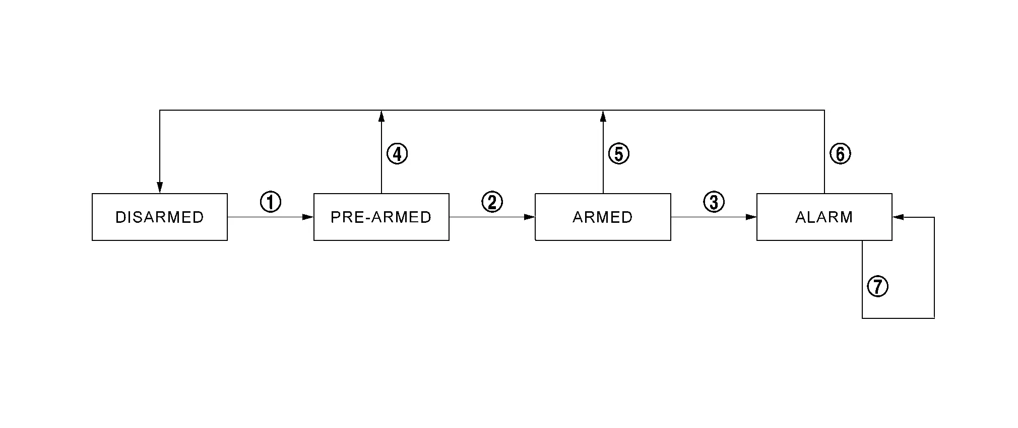
Operation Flow
| No. | System state | Switching condition | ||
|---|---|---|---|---|
 |
DISARMED to PRE-ARMED | When all conditions of A and one condition of B is satisfied. | A | B |
|
All doors are locked by:
|
|||
 |
PRE-ARMED to ARMED | When none of the following conditions are satisfied for 30 seconds. |
|
|
 |
ARMED to ALARM | When one of the following condition is satisfied. |
|
|
 |
PRE-ARMED to DISARMED | When one of the following condition is satisfied. |
|
|
 |
ARMED to DISARMED |
|||
 |
ALARM to DISARMED |
|||
 |
RE-ALARM | When one of the following condition is satisfied after the ALARM operation is finished. |
|
|
 NOTE:
NOTE:
To lock/unlock all doors by operating remote controller button of Intelligent Key or door request switch, Intelligent Key must be within the detection area of outside key antenna. For details, refer to System Description.
DISARMED Phase
The vehicle security system is not set in the DISARMED phase. The vehicle security system stays in this phase while Any door other than back door is open, because it is assumed that the owner is inside or nearby the Nissan Pathfinder vehicle.
When the vehicle security system is reset, each phase switches to the DISARMED phase directly.
PRE-ARMED Phase
The PRE-ARMED phase is the transient state between the DISARMED phase and the ARMED phase. This phase is maintained for 30 seconds, so that the owner can reset the setting due to a mis-operation. This phase switches to the ARMED phase when Nissan Pathfinder vehicle conditions are not changed for 30 seconds.
To reset the PRE-ARMED phase, refer to the switching condition of No. 4 in the table above.
ARMED Phase
The vehicle security system is set, and BCM monitors all necessary inputs. If any door or hood is opened without using Intelligent Key, Nissan Pathfinder vehicle security system switches to the ALARM phase.
To reset the ARMED phase, refer to the switching condition of No. 5 in the table above.
ALARM Phase
BCM transmits “horn request” signal and “High Beam Request” signal intermittently to IPDM E/R via CAN communication. In this phase, horns and headlamps are activated intermittently for approximately 27 seconds to warn that the Nissan Pathfinder vehicle is accessed by unauthorized means. After 27 seconds, the vehicle security system returns to the ARMED phase. At this time, if BCM still detects unauthorized access to the Nissan Pathfinder vehicle, the system is switched to the ALARM phase again. This RE-ALARM operation is carried out a maximum of 3 times.
To cancel the ALARM operation, refer to the switching condition of No. 6 in the table above.
 NOTE:
NOTE:
If a battery terminal is disconnected during the ALARM phase, theft warning alarm stops. But when the battery terminal is reconnected, theft warning alarm is activated again.
PANIC ALARM
-
The panic alarm function activates horns and headlamps intermittently when the owner presses the PANIC ALARM button of Intelligent Key outside the Nissan Pathfinder vehicle while the ignition switch is OFF.
-
When BCM receives panic alarm signal from Intelligent Key, BCM transmits “horn request” signal and “High Beam Request” signal intermittently to IPDM E/R via CAN communication. To prevent the activation due to mis-operation of Intelligent Key by owner, the panic alarm function is activated when BCM receives the signal for 0.4 - 0.6 seconds.
-
Panic alarm operation is maintained for approximately 27 seconds.
-
Panic alarm operation is canceled when BCM receives one of the following signals.
-
LOCK button of Intelligent Key: ON
-
UNLOCK button of Intelligent Key: ON
-
PANIC ALARM button of Intelligent Key: Pressed
-
Any door request switch: ON
-
-
Telematics system (horn & light) activates horns or horns and headlamps intermittently by Smartphone while the ignition switch is OFF.
-
Telematics system (horn & light) is operated 3 times for a total duration of approximately 15 seconds.
-
Telematics system (horn & light) operation is canceled when ignition switch ON.
Information Display (combination Meter) Nissan Pathfinder SUV
Remote Engine Start Information
DESIGN/PURPOSE
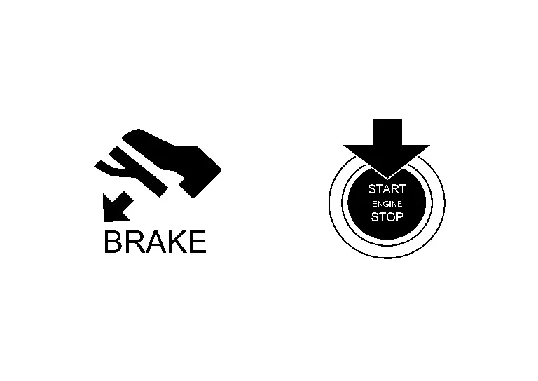
Information display informs the driver that the engine can be started.
| Symbol | Message |
|---|---|
|
|
Push brake and start switch to drive |
SYNCHRONIZATION WITH MASTER WARNING LAMP
Not applicable
SYSTEM DIAGRAM
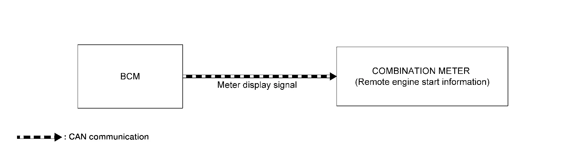
SIGNAL PATH
-
BCM transmits meter display signal to combination meter via CAN communication when remote engine run mode.
-
When combination meter receives meter display signal, combination meter display remote engine start information.
WARNING/INDICATOR OPERATION CONDITION
During remote engine run mode.
For details, refer to System Description.
WARNING/INDICATOR CANCEL CONDITION
Mode switch to normal engine run mode from remote engine run mode.
For details, refer to System Description.

Nissan Pathfinder (R53) 2022-2026 Service Manual
System
- Intelligent Key System/engine Start Function
- Nissan Vehicle Immobilizer System
- Vehicle Security System
- Information Display (combination Meter)
Contact Us
Nissan Pathfinder Info Center
Email: info@nipathfinder.com
Phone: +1 (800) 123-4567
Address: 123 Pathfinder Blvd, Nashville, TN 37214, USA
Working Hours: Mon–Fri, 9:00 AM – 5:00 PM (EST)
