Nissan Pathfinder: Drive Mode System - Component Parts. Drive Mode System
Nissan Pathfinder (R53) 2022-2026 Service Manual / Cruise Control & Driver Assistance :: Drive Mode System / System Description / Component Parts. Drive Mode System
Component Parts Location
2WD MODELS
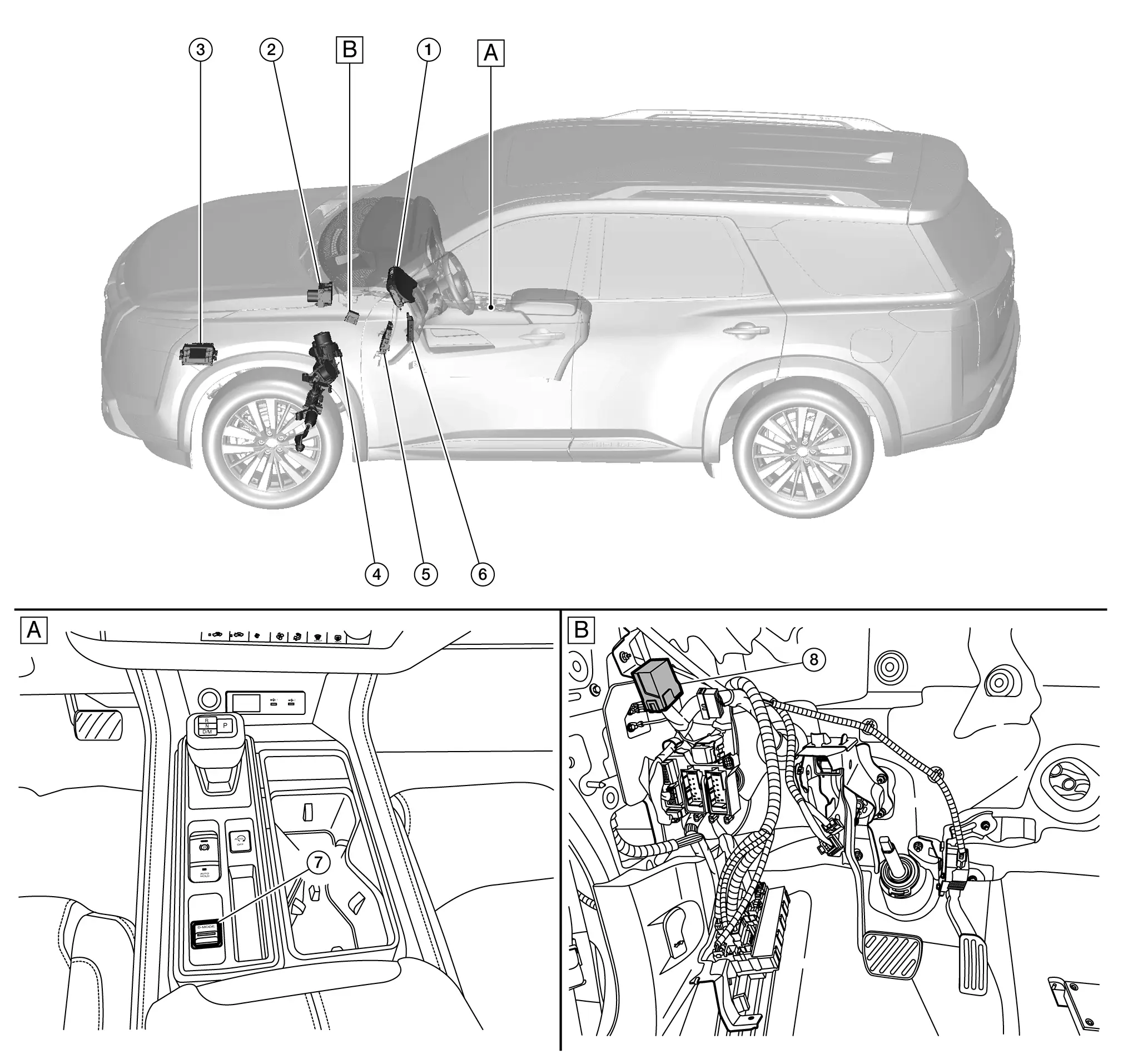
| A. |
Center console finisher assembly |
B. |
Upside of instrument lower panel LH |
| No. | Component | Description |
|---|
| 1. |
Combination meter |
-
Combination meter receives the following signals from chassis control module:
-
Combination meter displays the status of drive mode selected by the driver on the information display according to the received signal.
Refer to Component Parts Location (full TFT meter), Component Parts Location (7 inch information display meter) for detailed component location. |
| 2. |
ABS (Anti-lock Braking System) actuator and electric unit (control unit) |
-
ABS actuator and electric unit (control unit) receives the following signals from chassis control module:
-
ABS actuator and electric unit (control unit) controls the active trace control function according to the received signal.
Refer to Component Parts Location for detailed component location. |
| 3. |
ECM (Engine Control Module) |
-
ECM receives the following signal from chassis control module:
-
ECM controls throttle angle characteristics and torque according to the received signal and transmits the following signals to ADAS control unit 2.
Refer to Component Parts Location for detailed component location. |
| 4. |
EPS (Electric Power Steering) control unit |
Refer to Component Parts Location for detailed component location. |
| 5. |
BCM (Body Control Module) |
Refer to Component Parts Location for detailed component location. |
| 6. |
ADAS (Advanced Driver Assistance System) control unit 2 |
-
ADAS control unit 2 receives the following signal from chassis control module:
-
ADAS control unit 2 controls accelerator reaction force of accelerator pedal actuator according to the received signal and transmits the following signals to accelerator pedal actuator.
Refer to Component Parts Location for detailed component location. |
| 7. |
Drive mode select switch (2WD) |
Refer to Drive Mode Select Switch. |
| 8. |
Chassis control module |
Refer to Component Parts Location for detailed component location. |
4WD MODELS
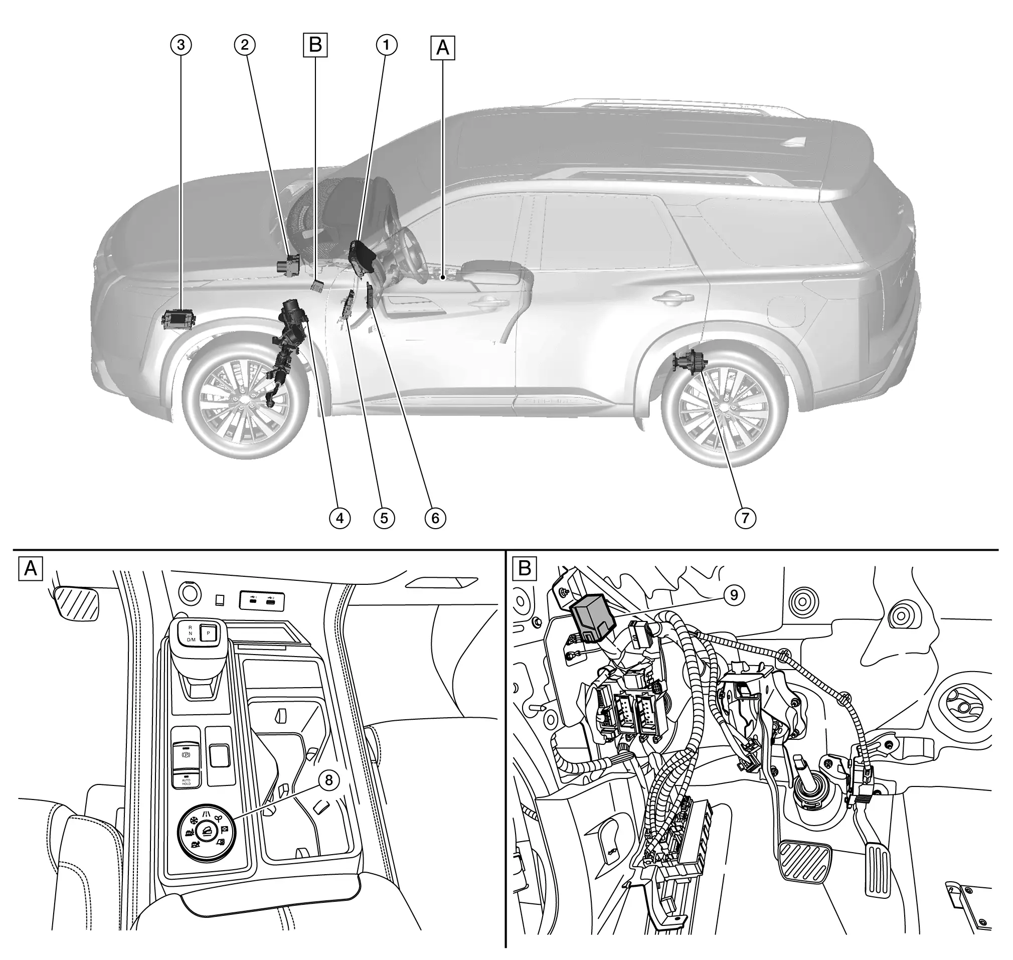
| A. |
Center console finisher assembly |
B. |
Upside of instrument lower panel LH |
| No. | Component | Description |
|---|
| 1. |
Combination meter |
-
Combination meter receives the following signals from chassis control module:
-
Combination meter displays the status of drive mode selected by the driver on the information display according to the received signal.
Refer to Component Parts Location (full TFT meter), Component Parts Location (7 inch information display meter) for detailed component location. |
| 2. |
ABS (Anti-lock Braking System) actuator and electric unit (control unit) |
-
ABS actuator and electric unit (control unit) receives the following signals from chassis control module:
-
ABS actuator and electric unit (control unit) controls the active trace control function according to the received signal.
Refer to Component Parts Location for detailed component location. |
| 3. |
ECM (Engine Control Module) |
-
ECM receives the following signal from chassis control module:
-
ECM controls throttle angle characteristics and torque according to the received signal and transmits the following signals to ADAS control unit 2:
Refer to Component Parts Location for detailed component location. |
| 4. |
EPS (Electric Power Steering) control unit |
Refer to Component Parts Location for detailed component location. |
| 5. |
BCM (Body Control Module) |
Refer to Component Parts Location for detailed component location. |
| 6. |
ADAS (Advanced Driver Assistance System) control unit 2 |
-
ADAS control unit 2 receives the following signal from chassis control module:
-
ADAS control unit 2 controls accelerator reaction force of accelerator pedal actuator according to the received signal and transmits the following signals to accelerator pedal actuator:
Refer to Component Parts Location for detailed component location. |
| 7. |
4WD control unit |
Refer to Component Parts Location for detailed component location. |
| 8. |
Drive mode select switch (4WD) |
Refer to Drive Mode Select Switch. |
| 9. |
Chassis control module |
Refer to Component Parts Location for detailed component location. |
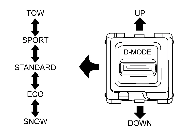
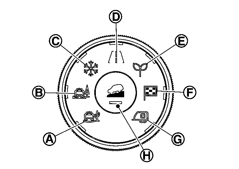
Drive Mode Select Switch
FUNCTIONS WITHIN THE SYSTEM
When drive mode select switch is operated, driving mode is changed for each system.
INDIVIDUAL FUNCTIONS WITHIN THE SYSTEM
Drive mode select switch detected the mode status.
INDIVIDUAL OPERATION
Transmit the drive mode select switch signal to BCM.
PARTS LOCATION
Refer to Component Parts Location.
 :
:  :
:  :
:  :
:  :
:  :
:  :
:  :
:  NOTE:
NOTE:

