Nissan Pathfinder: System Description - System ++
System Description
-
Chassis control to integrally control the driving system was adopted.
-
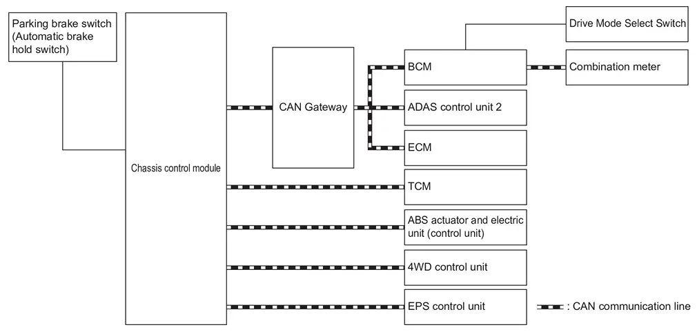
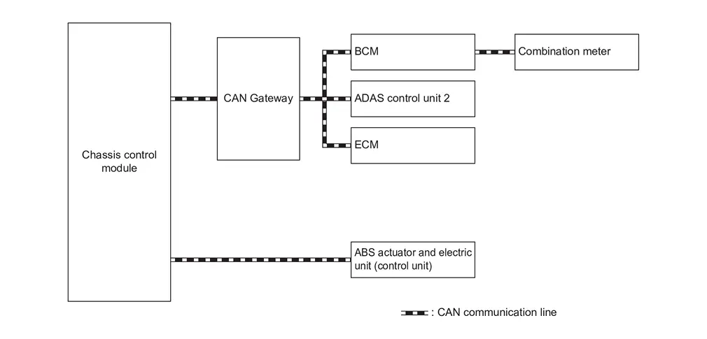
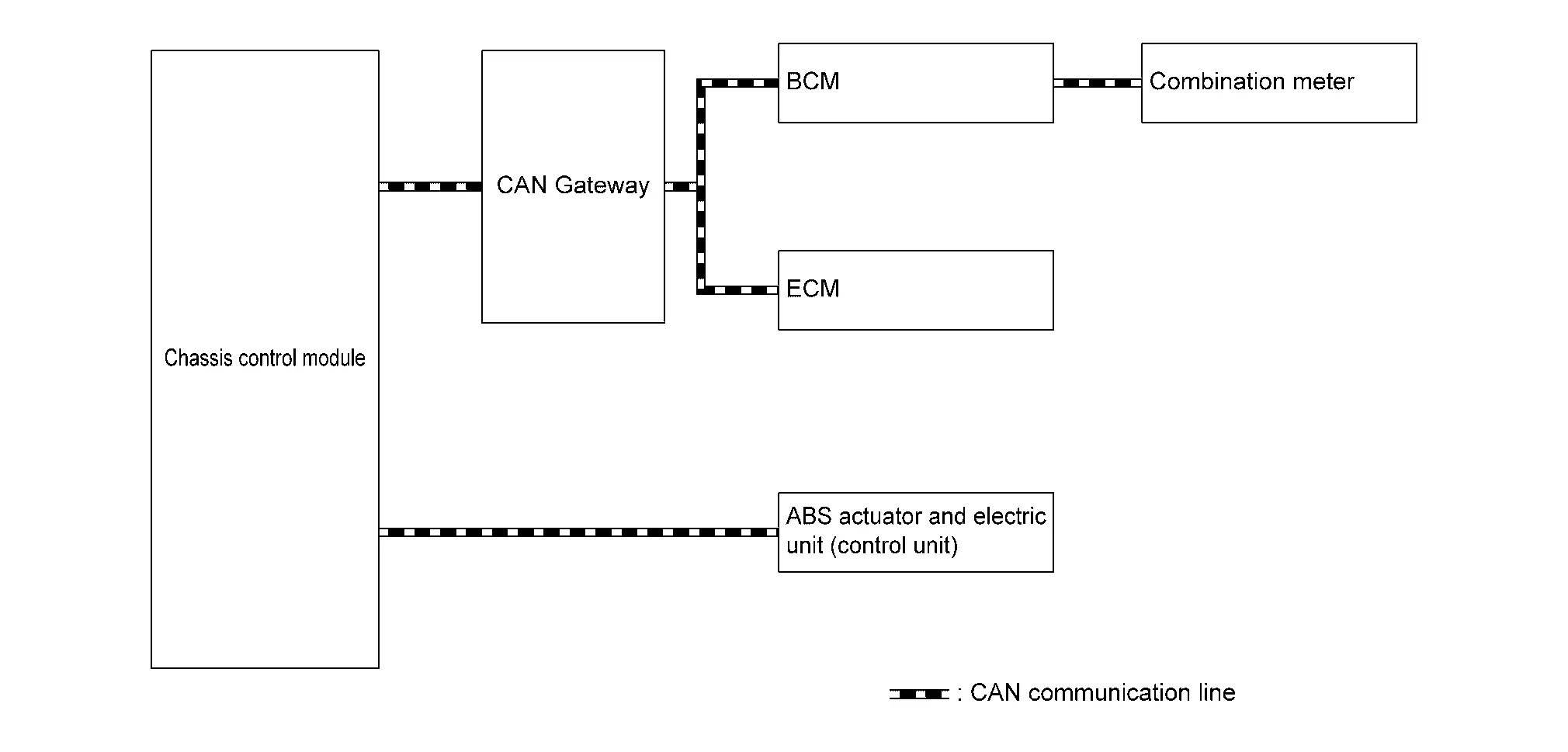
Chassis control module inputs the necessary information for control from CAN communication and each switch and integrally controls each system. Refer to the following table for systems controlled and input output signals.
| Function | Reference page | |
|---|---|---|
| Intelligent trace control function | System Description | |
| Active ride control function (if equipped) | System Description | |
| Automatic brake hold function | System Description | |
| Drive mode selector function | System Description (2WD Models), System Description (4WD Models). | |
SYSTEM DIAGRAM
 NOTE:
NOTE:
4WD control unit is applied to 4WD models.
INPUT SIGNAL AND OUTPUT SIGNAL
Major signal transmission between each unit via communication lines is shown in the following table.
| Component parts | Signal description |
|---|---|
| ECM |
Mainly transmits the following signals to chassis control module via CAN communication.
Mainly receives the following signals from chassis control module via CAN communication.
|
| ABS actuator and electric unit (control unit) |
Mainly transmits the following signals to chassis control module via CAN communication.
Mainly receives the following signals from chassis control module via CAN communication.
|
| BCM |
Mainly transmits the following signals to chassis control module via CAN communication.
|
| TCM |
Mainly transmits the following signals to chassis control module via CAN communication.
|
| Combination meter |
Mainly receives the following signals from chassis control module via CAN communication.
|
| 4WD control unit* |
Mainly receives the following signals from chassis control module via CAN communication.
|
| ADAS control unit 2 |
Mainly transmits the following signals to chassis control module via CAN communication.
Mainly receives the following signals from chassis control module via CAN communication.
|
| EPS control unit |
Mainly receives the following signals from chassis control module via CAN communication.
|
*: 4WD models
MAC (MESSAGE AUTHENTICATION CODE)
MAC (Message Authentication Code) is a function that prevents unauthorized communication from other than the ECU with MAC function by secure authentication communication. Chassis control module can write a MAC key required for communication between the ECUs and perform MAC diagnosis.
Fail-safe
When a malfunction occurs in the chassis control module, the master warning lamp turns ON and an interrupt is displayed on the information display of the combination meter.
| DTC | Fail-safe condition |
|---|---|
| C1B80-54 |
The following functions are suspended.
|
| C1B81-55 | |
| C1B8F-82 |
The following functions are suspended.
|
| C1B92-82 |
The following functions are suspended.
|
| C1B93-82 |
The following functions are suspended.
|
| C1B94-82 |
The following functions are suspended.
|
| C1B96-82 |
The following functions are suspended.
|
| C1B97-82 |
The following functions are suspended.
|
| C1BB4-44 |
The following functions are suspended.
|
| C1BB4-45 |
The following functions are suspended.*
|
| C1BB4-46 | |
| C1BB4-49 |
The following functions are suspended.
|
| U0076-00 |
The following functions are suspended.*
|
| U007A-00 | |
| U1327-52 | |
| U1327-54 | |
| U2140-57 | - |
| U2140-83 |
The following functions are suspended.
|
| U2140-87 | |
| U214F-57 | - |
| U214F-83 |
The following functions are suspended.
|
| U214F-87 |
The following functions are suspended.
|
| U2152-57 | - |
| U2152-83 | Normal control |
| U2152-87 |
The following functions are suspended.
|
| U215B-83 |
The following functions are suspended.
|
| U215B-87 | |
| U2165-57 | - |
| U2248-83 |
The following functions are suspended.
|
| U2248-87 | |
| U2448-87 |
The following functions are suspended.
|
| U2541-83 |
The following functions are suspended.
|
| U2541-87 | |
| U2A03-88 |
The following functions are suspended.*
|
| U2A0B-88 | |
| U2A0E-88 |
*: Depends on the DTC detection status
Intelligent Trace Control Function
System Description
-
This function senses driving based on the driver’s steering and acceleration/braking patterns, and controls brake pressure at individual wheels to aid tracing at corners and help smooth Nissan Pathfinder vehicle response.
-
Amount of brake control is changed based on drive mode select switch.
-
When the VDC function is turned OFF, intelligent trace control function is also turned OFF.
-
When intelligent trace control function is not functioning properly, the master warning lamp illuminates, and Warning message will also appear on information display.
 NOTE:
NOTE: -
Intelligent trace control function is not always activated in any driving conditions.
-
When the intelligent trace control function is activated, the driver may feel some vibration on the brake pedal, hear operating sound, or have feel of the deceleration. This is not a malfunction because it is caused by intelligent trace control function that is normally operated.
-
OPERATION CHARACTERISTICS
-
Transient steering input - Reduces lag of yaw rate against steering operation.
-
The brake is controlled according to the steering operation condition of the driver and the cornering condition of the Nissan Pathfinder vehicle.
-
-
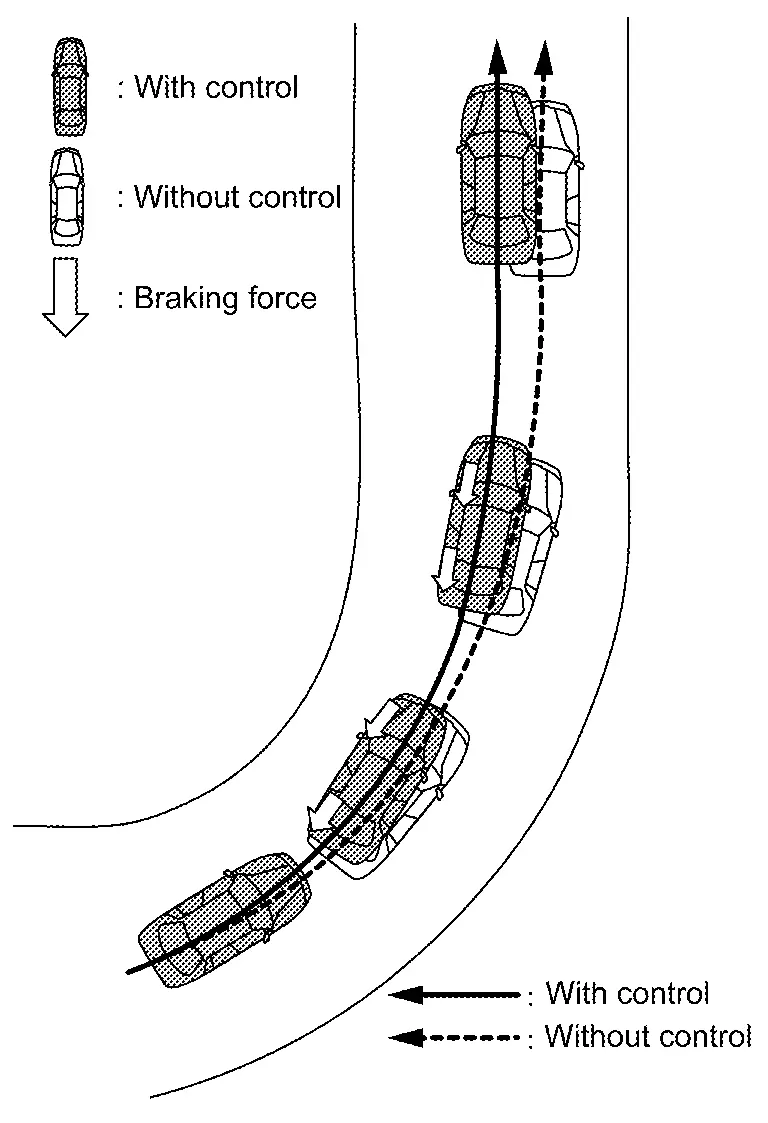
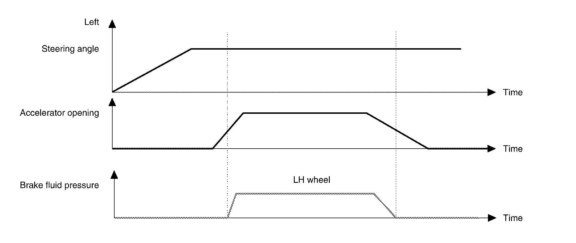
Acceleration at corners - Restrains understeer by applying the necessary amount of brake pressure to the inner wheels.
-
The brake is controlled according to the steering operation condition of the driver and the cornering condition of the Nissan Pathfinder vehicle.
-
-
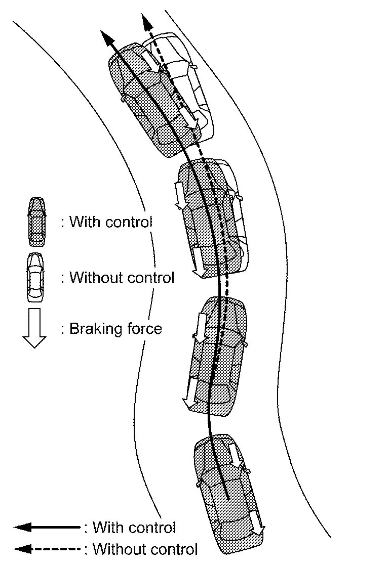
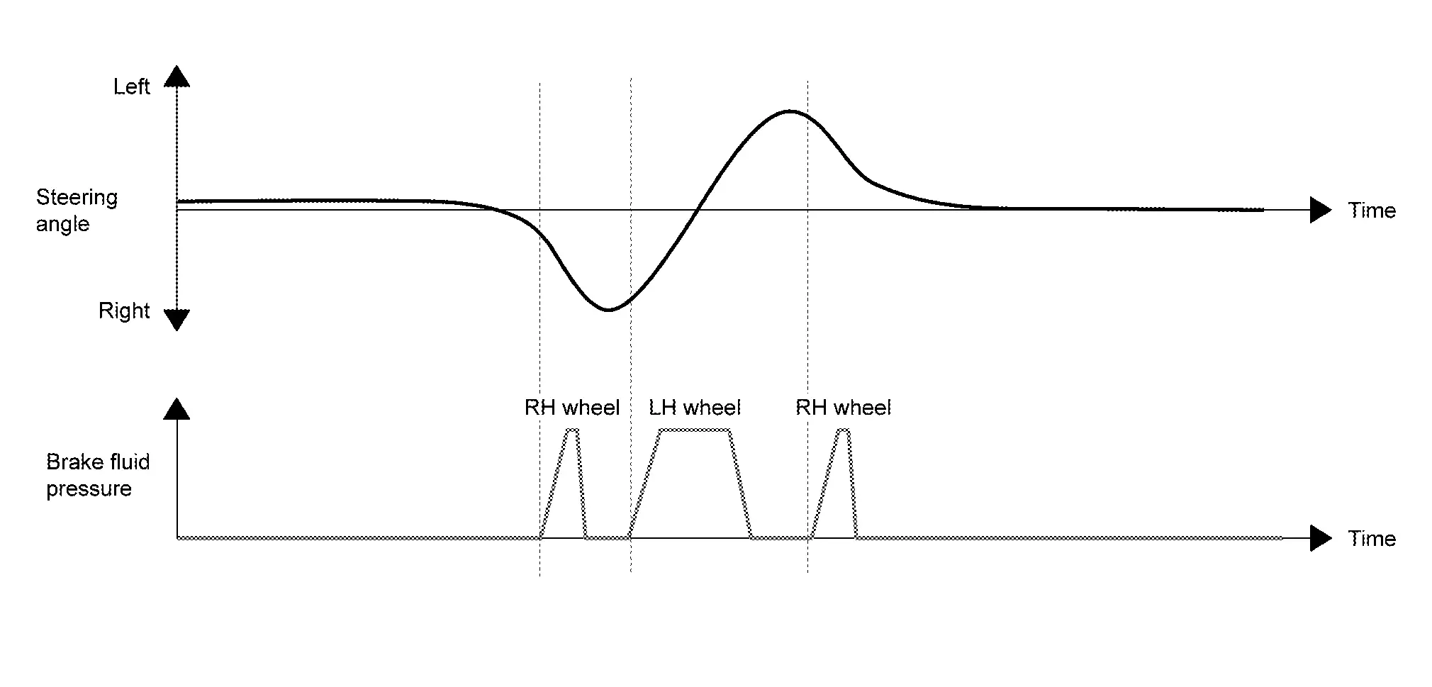
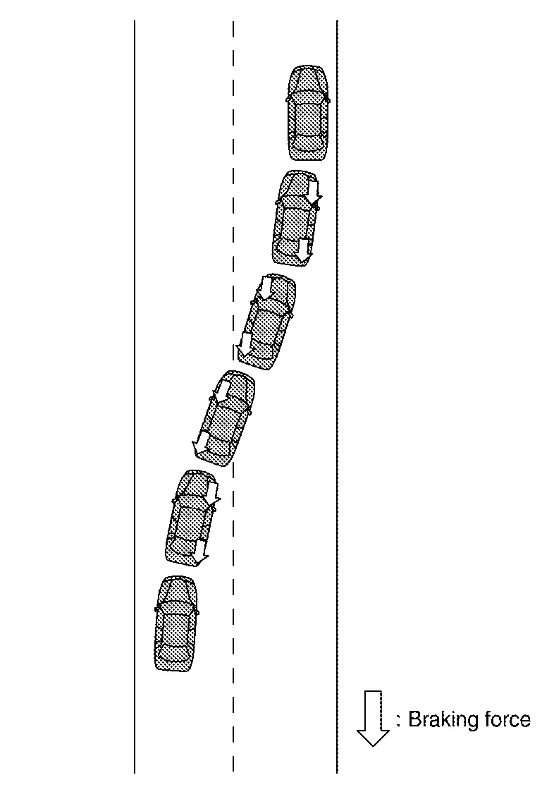
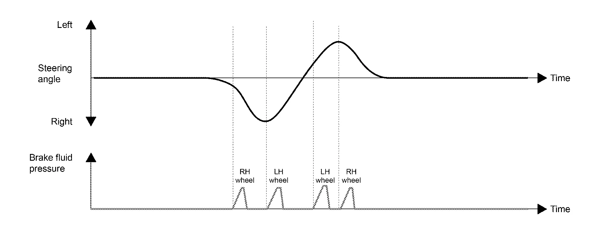
Quick lane change - achieves stable Nissan Pathfinder vehicle behavior at quick steering operation by applying the necessary amount of brake pressure to the appropriate wheels.
-
The brake is controlled according to the steering operation condition of the driver and the cornering condition of the Nissan Pathfinder vehicle.
-
SYSTEM DIAGRAM
INPUT SIGNAL AND OUTPUT SIGNAL
Major signal transmission between each unit via communication lines is shown in the following table.
| Component parts | Signal description |
|---|---|
| ECM |
Mainly transmits the following signals to chassis control module via CAN communication.
|
| ABS actuator and electric unit (control unit) |
Mainly transmits the following signals to chassis control module via CAN communication.
Mainly receives the following signals from chassis control module via CAN communication.
|
| Combination meter |
Mainly receives the following signals from chassis control module via CAN communication.
|
| ADAS control unit 2 |
Mainly transmits the following signals to chassis control module via CAN communication.
|
Active Ride Control Function (if Equipped)
System Description
-
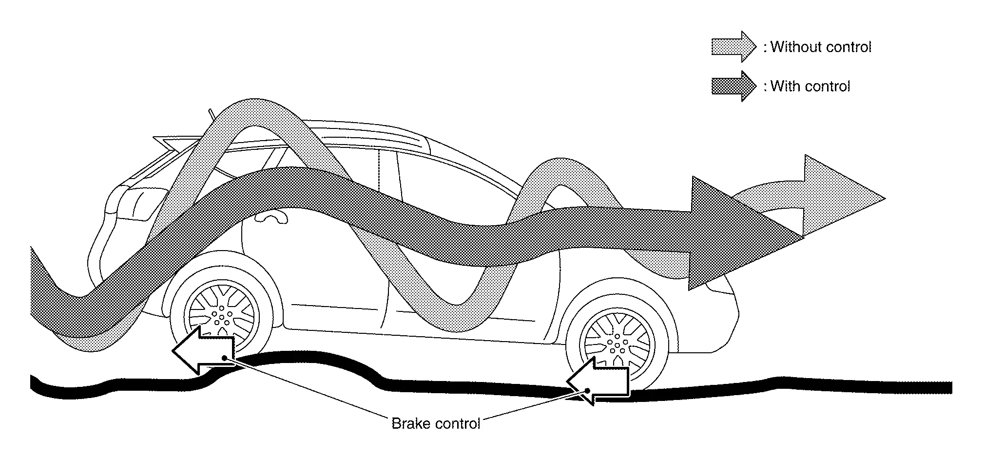
Active ride control function senses upper body motion and controls four wheel brake pressure. This will enhance ride comfort in effort to restrain uncomfortable upper body movement when passing over undulated road surfaces.
-
When the VDC function is turned OFF, active ride control function is also turned OFF.
-
When active ride control function is not functioning properly, the master warning lamp illuminates, and Warning message will also appear on information display.
 NOTE:
NOTE: -
Active ride control function is not always activated in any driving conditions.
-
When the active ride control function is activated, the driver may feel some vibration on the brake pedal, hear operating sound, or have feel of the deceleration. This is not a malfunction because it is caused by active ride control function that is normally operated.
-
BRAKING CONTROL
-
Brake control - Enhances ride comfort by restraining upper body movement with small amount of brake control when driving on bumpy roads.
SYSTEM DIAGRAM
INPUT SIGNAL AND OUTPUT SIGNAL
Major signal transmission between each unit via communication lines is shown in the following table.
| Component parts | Signal description |
|---|---|
| ECM |
Mainly transmits the following signals to chassis control module via CAN communication.
|
| ABS actuator and electric unit (control unit) |
Mainly transmits the following signals to chassis control module via CAN communication.
Mainly receives the following signals from chassis control module via CAN communication.
|
| Combination meter |
Mainly receives the following signals from chassis control module via CAN communication.
|
Information Display (combination Meter)
Chassis Control Warning
DESIGN/PURPOSE
The warning message is displayed on the information display when “Chassis Control” detected the system malfunction.
Warning Message
| Design | Warning Message |
|---|---|
| — |
Chassis Control System Error See Owner’s Manual |
SYNCHRONIZATION WITH MASTER WARNING LAMP
Applicable
SYNCHRONIZATION WITH WARNING CHIME
Not applicable
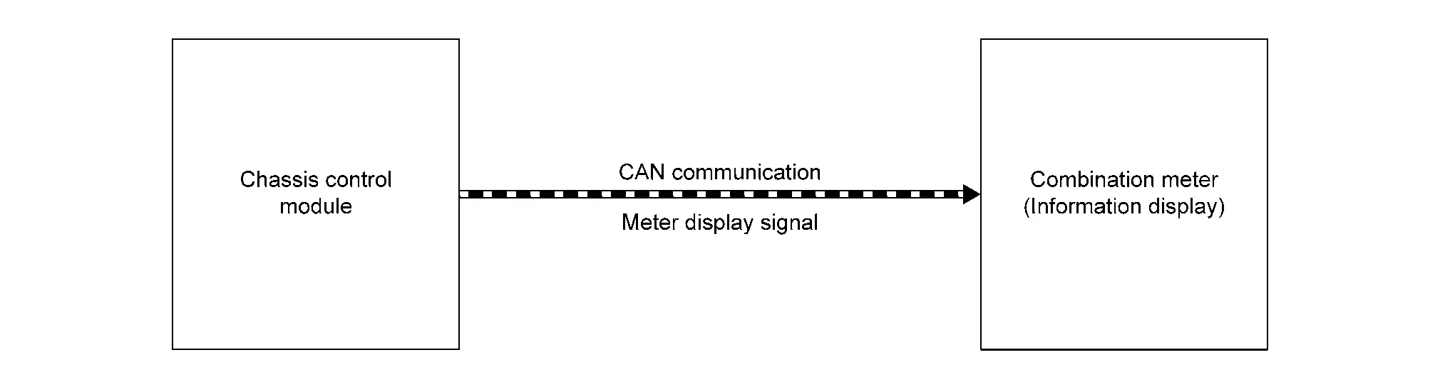
SYSTEM DIAGRAM
SIGNAL PATH
-
The chassis control module transmits the meter display signal to the combination meter via CAN communication.
-
The combination meter shows the chassis control warning on the information display, according to the signal.
WARNING MESSAGE DISPLAY CONDITION
When all of the following conditions are satisfied
-
Ignition switch is ON
-
Chassis control system malfunction is detected. Refer to DTC Index.

Nissan Pathfinder (R53) 2022-2026 Service Manual
Contact Us
Nissan Pathfinder Info Center
Email: info@nipathfinder.com
Phone: +1 (800) 123-4567
Address: 123 Pathfinder Blvd, Nashville, TN 37214, USA
Working Hours: Mon–Fri, 9:00 AM – 5:00 PM (EST)
