Nissan Pathfinder: Body Repair - Removal and Installation
Corrosion Protection Nissan Pathfinder Fifth generation
Description
To provide improved corrosion prevention, the following anti-corrosive measures have been implemented in NISSAN production plants. When repairing or replacing body panels, it is necessary to use the same anti-corrosive measures.
Anti-Corrosive Precoated Steel (Galvannealed Steel)
To improve repairability and corrosion resistance, a new type of anti-corrosive precoated steel sheet has been adopted, replacing conventional zinc-coated steel sheet.
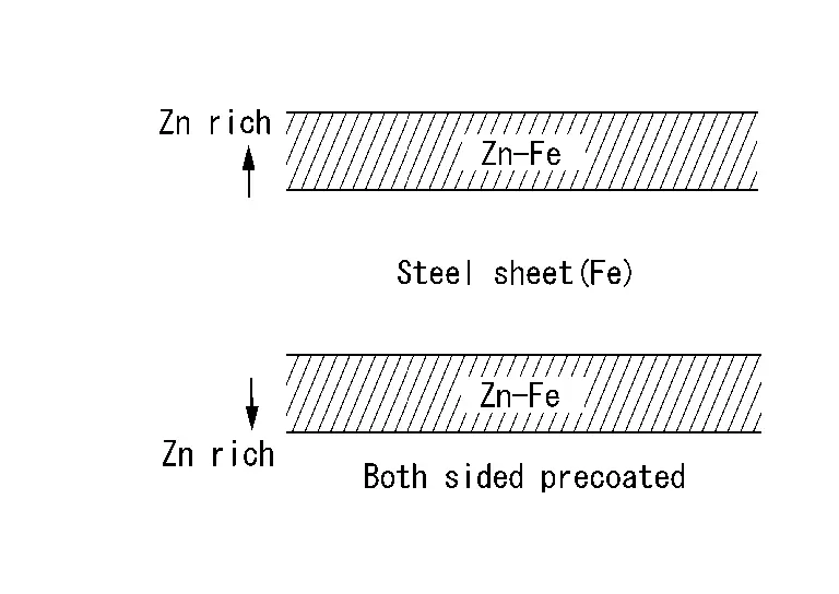
Galvannealed steel is electroplated and heated to form zinc-iron alloy, which provides excellent and long term corrosion resistance with cationic electrodeposition primer.
Nissan Genuine Service Parts are fabricated from galvannealed steel. Therefore, it is recommended that GENUINE NISSAN PARTS or equivalent be used for panel replacement to maintain the anti-corrosive performance built into the Nissan Pathfinder vehicle at the factory.
Phosphate Coating Treatment and Cationic Electrodeposition Primer
A phosphate coating treatment and a cationic electrodeposition primer, which provide excellent corrosion protection, are employed on all body components.
CAUTION:
Confine paint removal during welding operations to an absolute minimum.
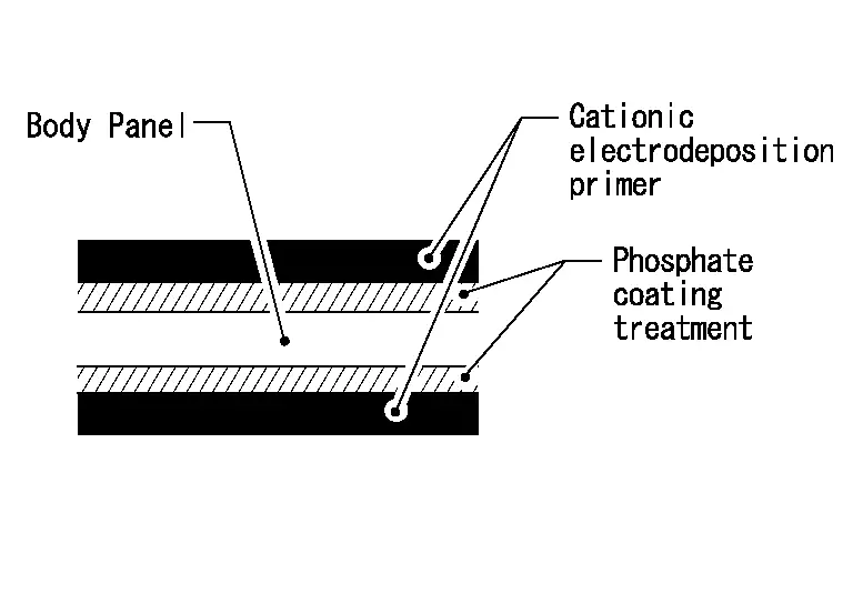
Nissan Genuine Service Parts are also treated in the same manner. Therefore, it is recommended that GENUINE NISSAN PARTS or equivalent be used for panel replacement to maintain anti-corrosive performance built into the Nissan Pathfinder vehicle at the factory.
Undercoating
The underside of the floor and wheelhouse are undercoated to prevent rust, vibration, noise and stone chipping. Therefore, when such a panel is replaced or repaired, apply undercoating to that part. Use an undercoating which is rust preventive, soundproof, vibration-proof, shock-resistant, adhesive, and durable.
PRECAUTIONS IN UNDERCOATING
-
Do not apply undercoating unless specified. Avoid areas such as the areas above the muffler and three-way catalyst which are subjected to heat.
-
Do not undercoat the exhaust pipe or other parts which become hot.
-
Do not undercoat rotating parts.
-
Apply cavity wax after applying undercoating.
-
After putting seal on the Nissan Pathfinder vehicle, put undercoating on it.
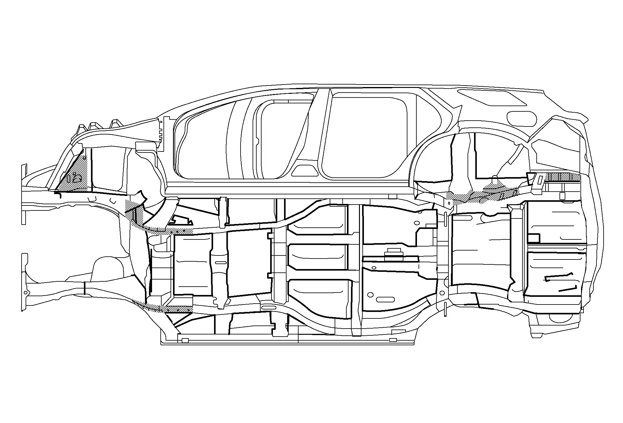
UNDERCOATED AREAS
|
 : Sealed portions : Sealed portions |
 : Undercoated areas
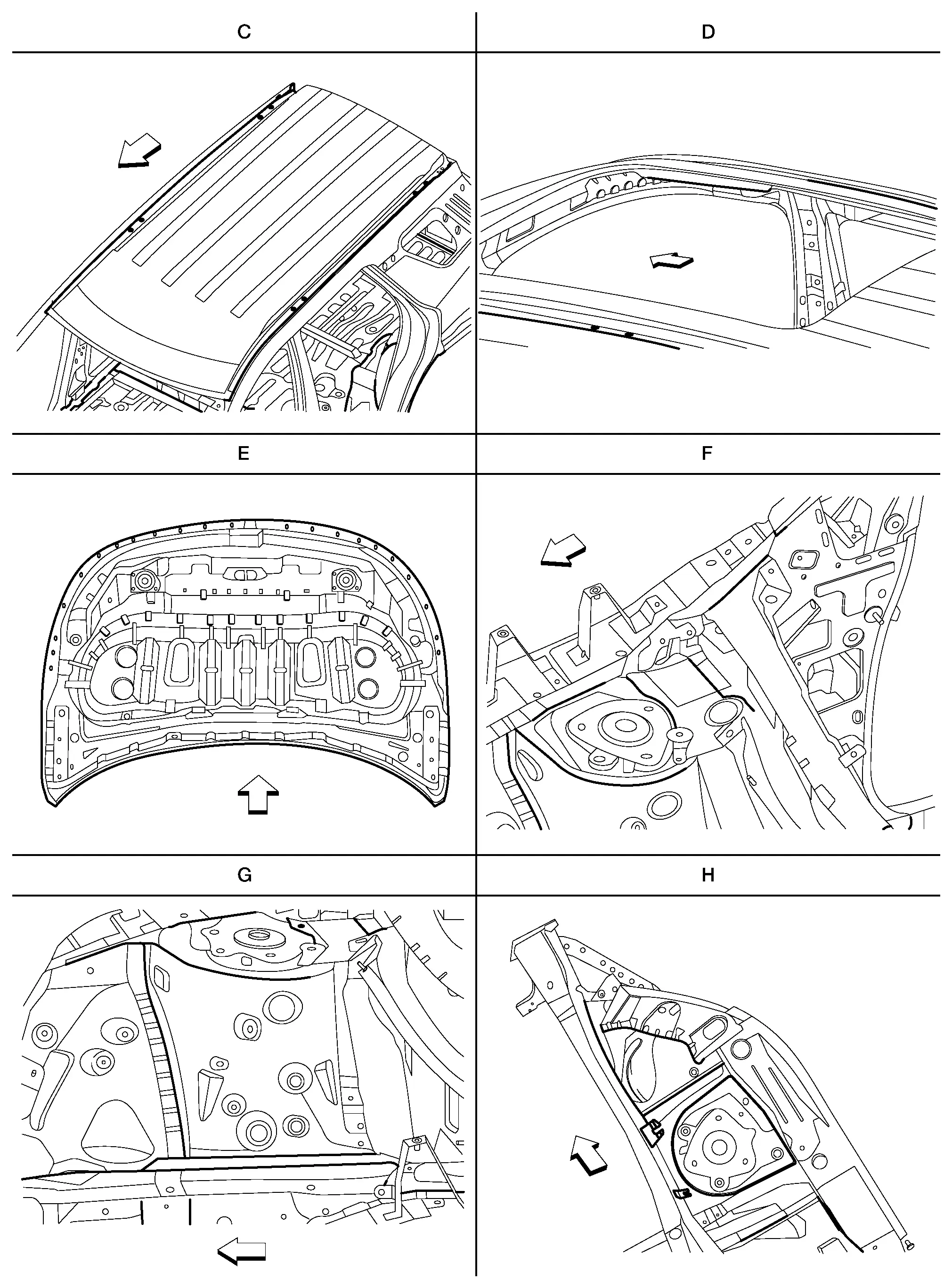
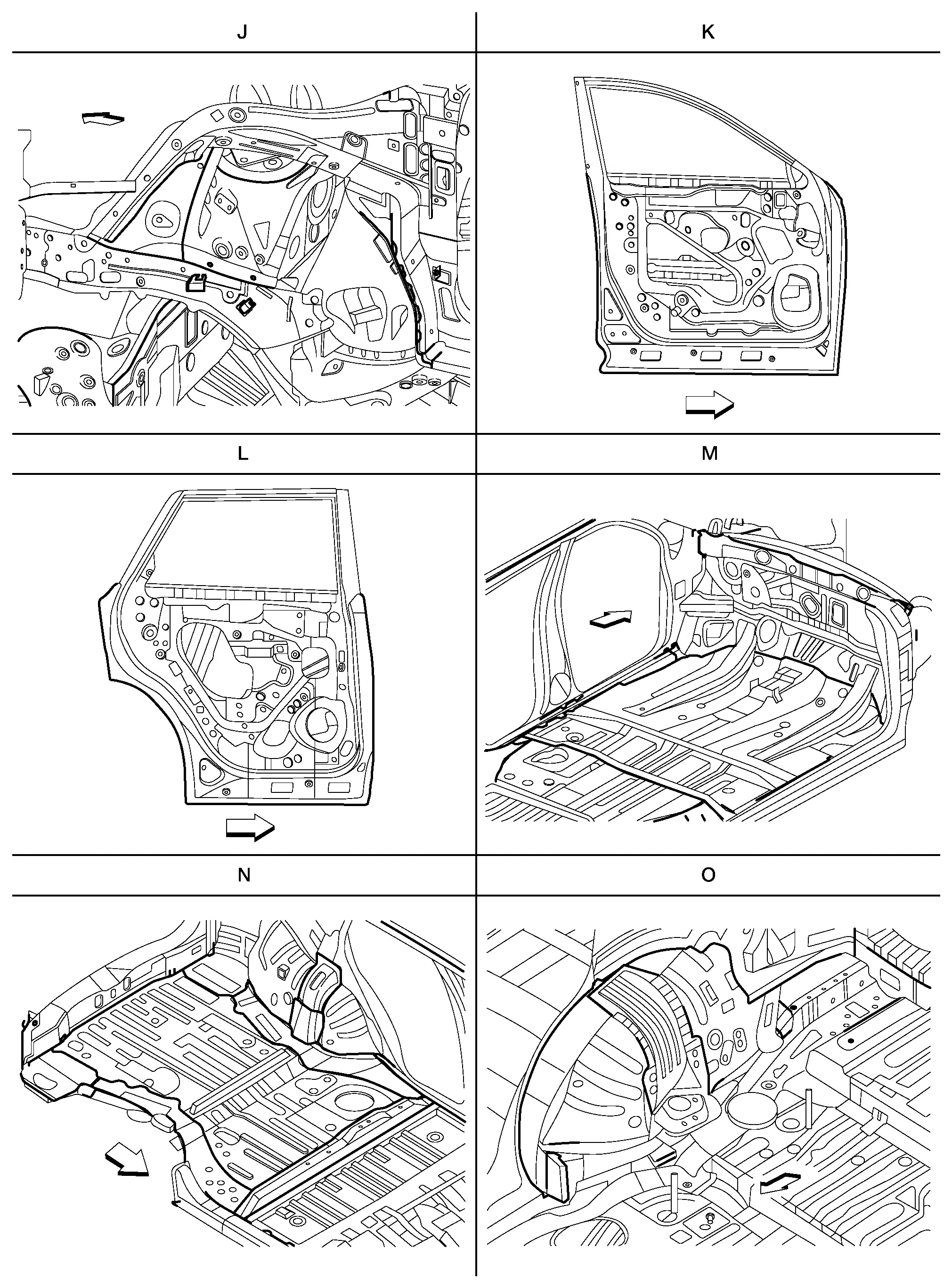
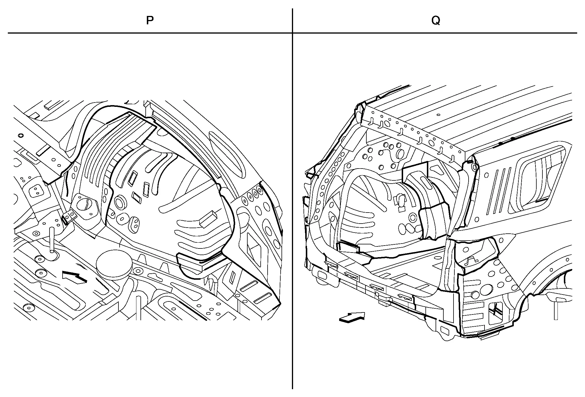
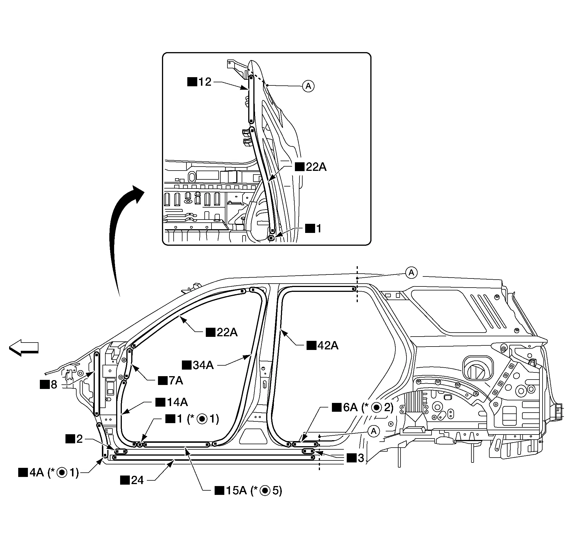
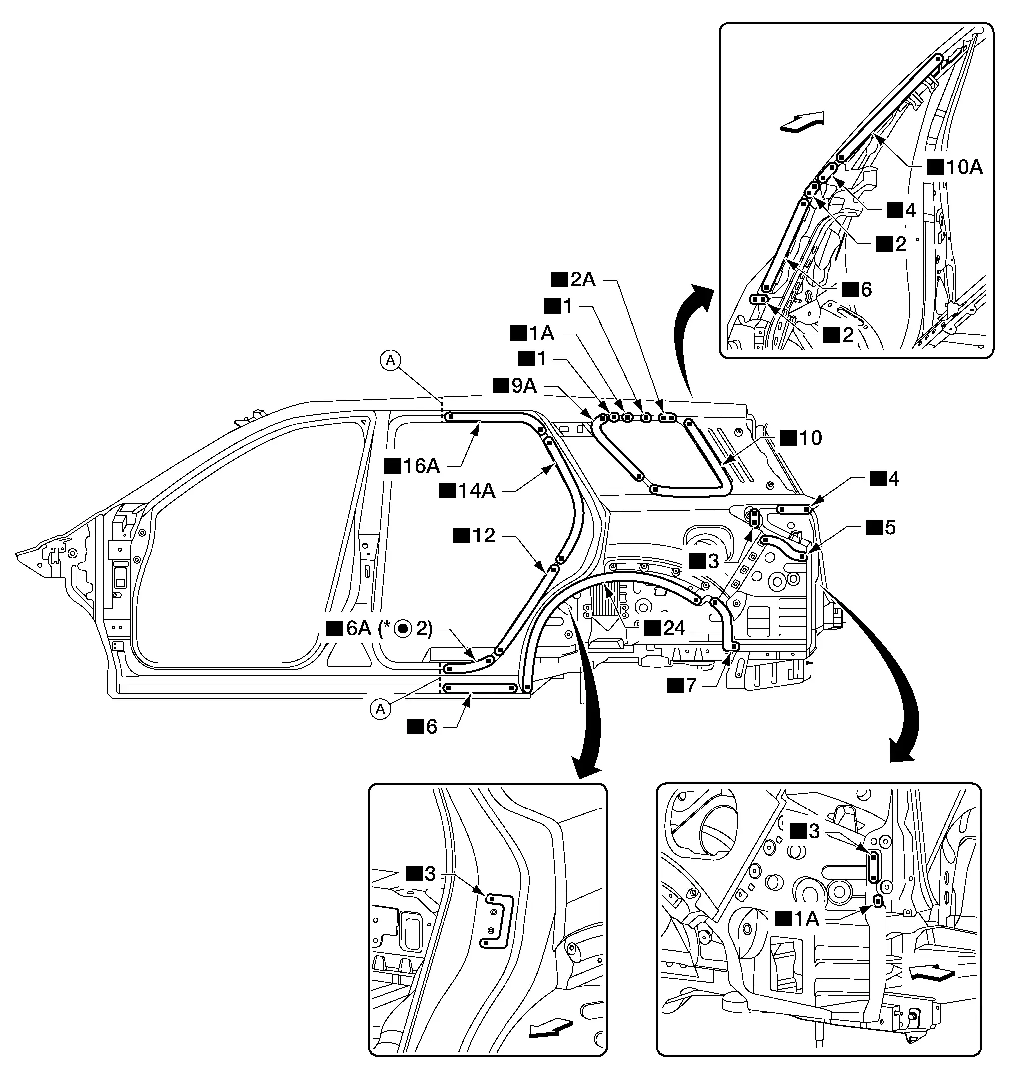
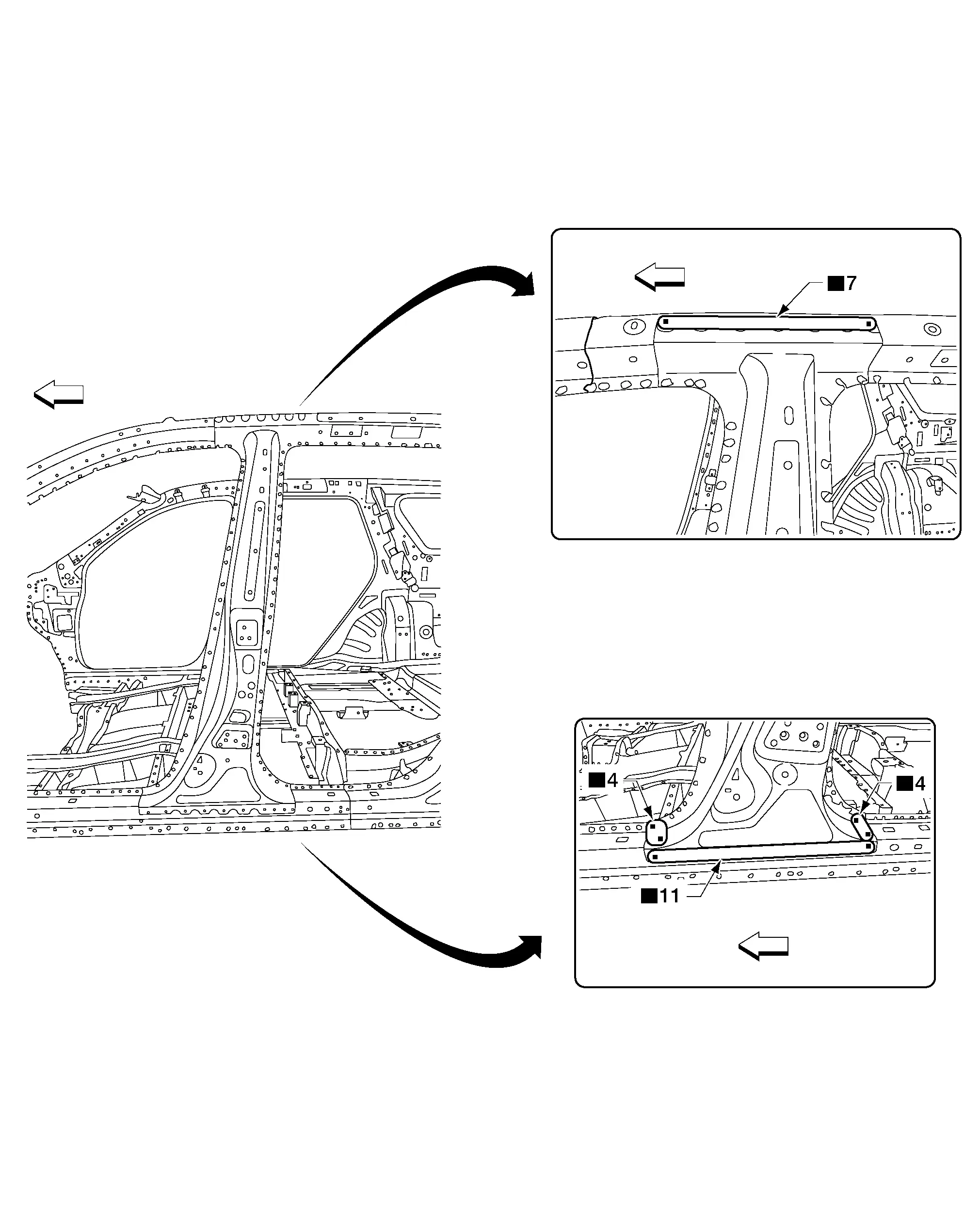
Body Sealing Nissan Pathfinder 2022
Description
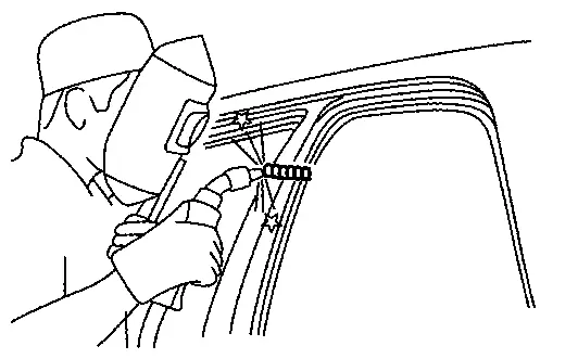
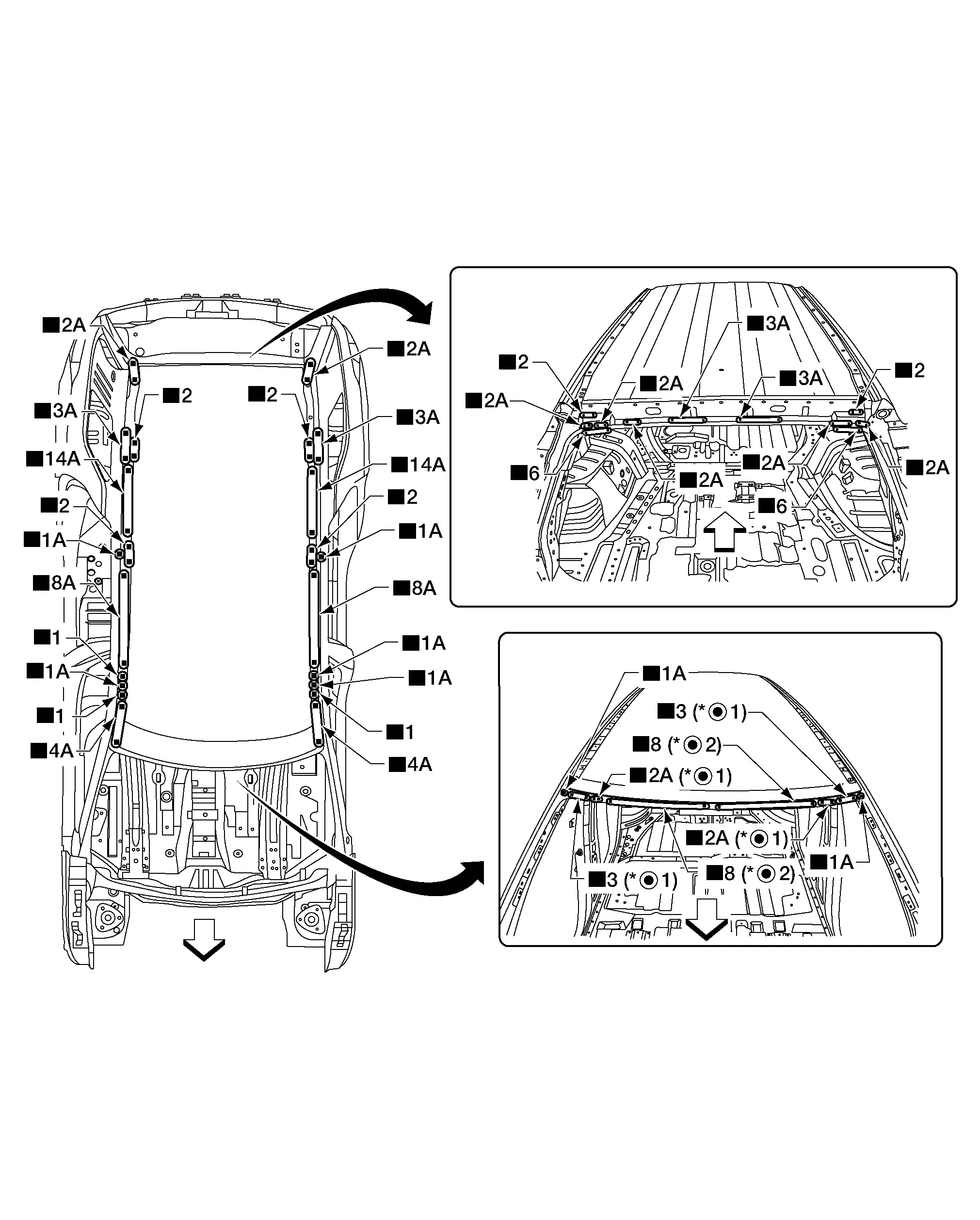
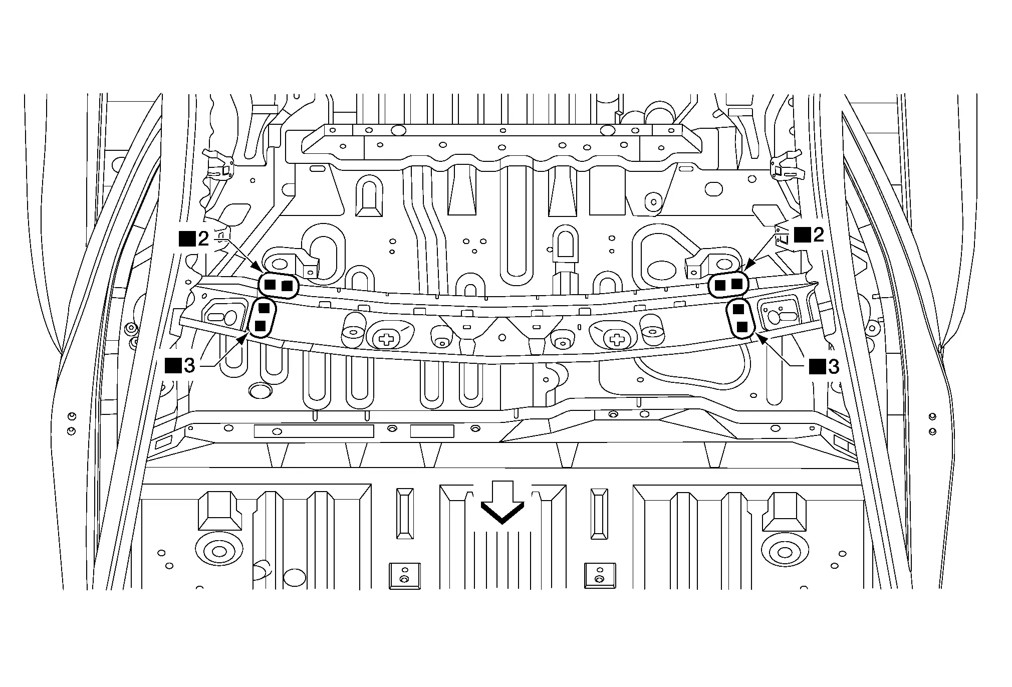
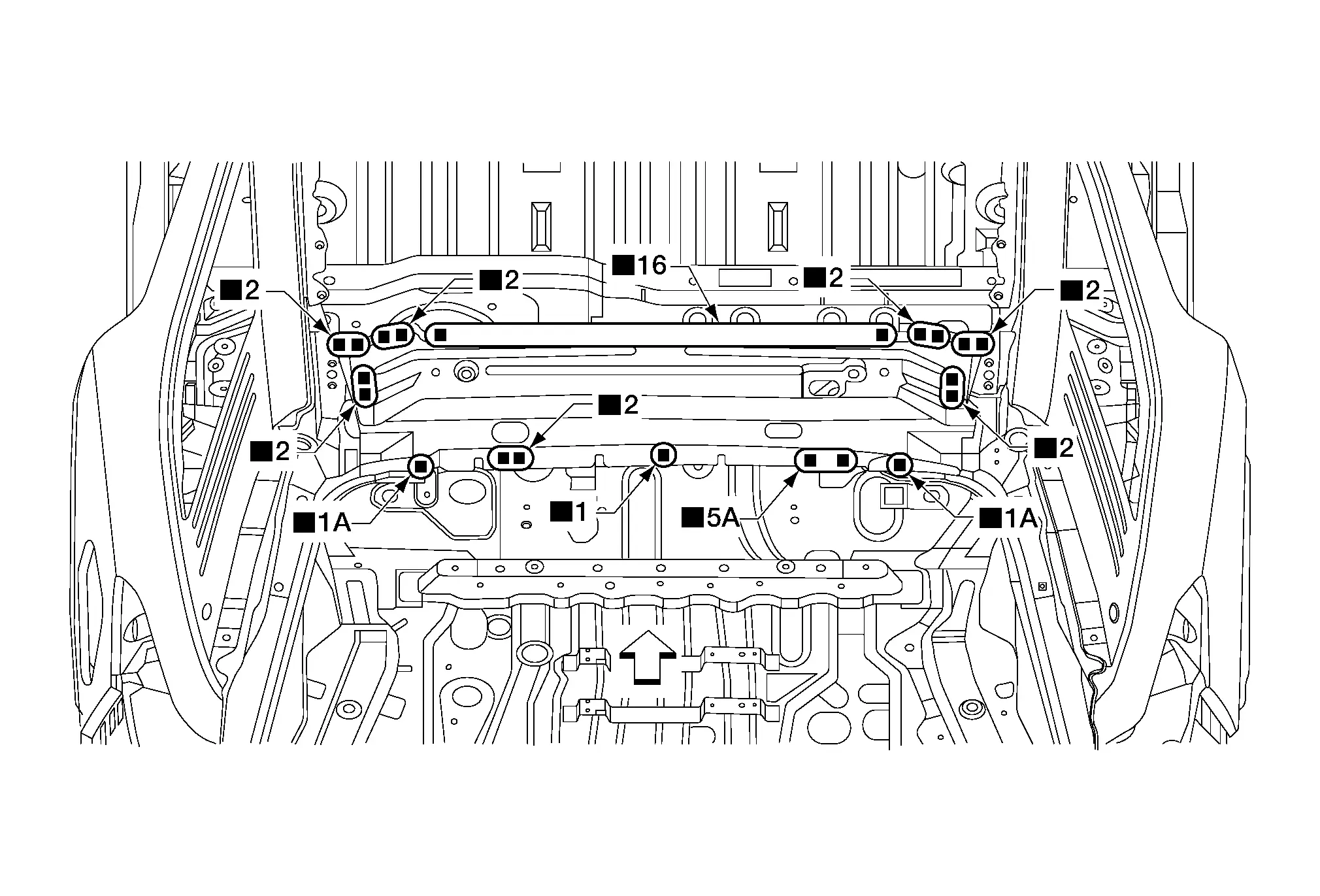
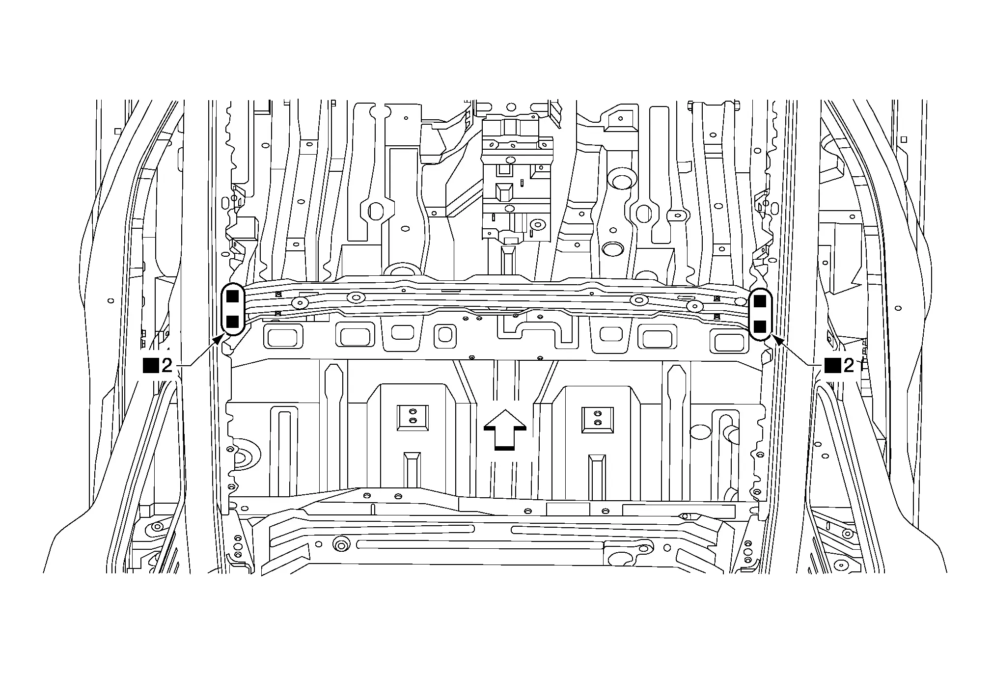
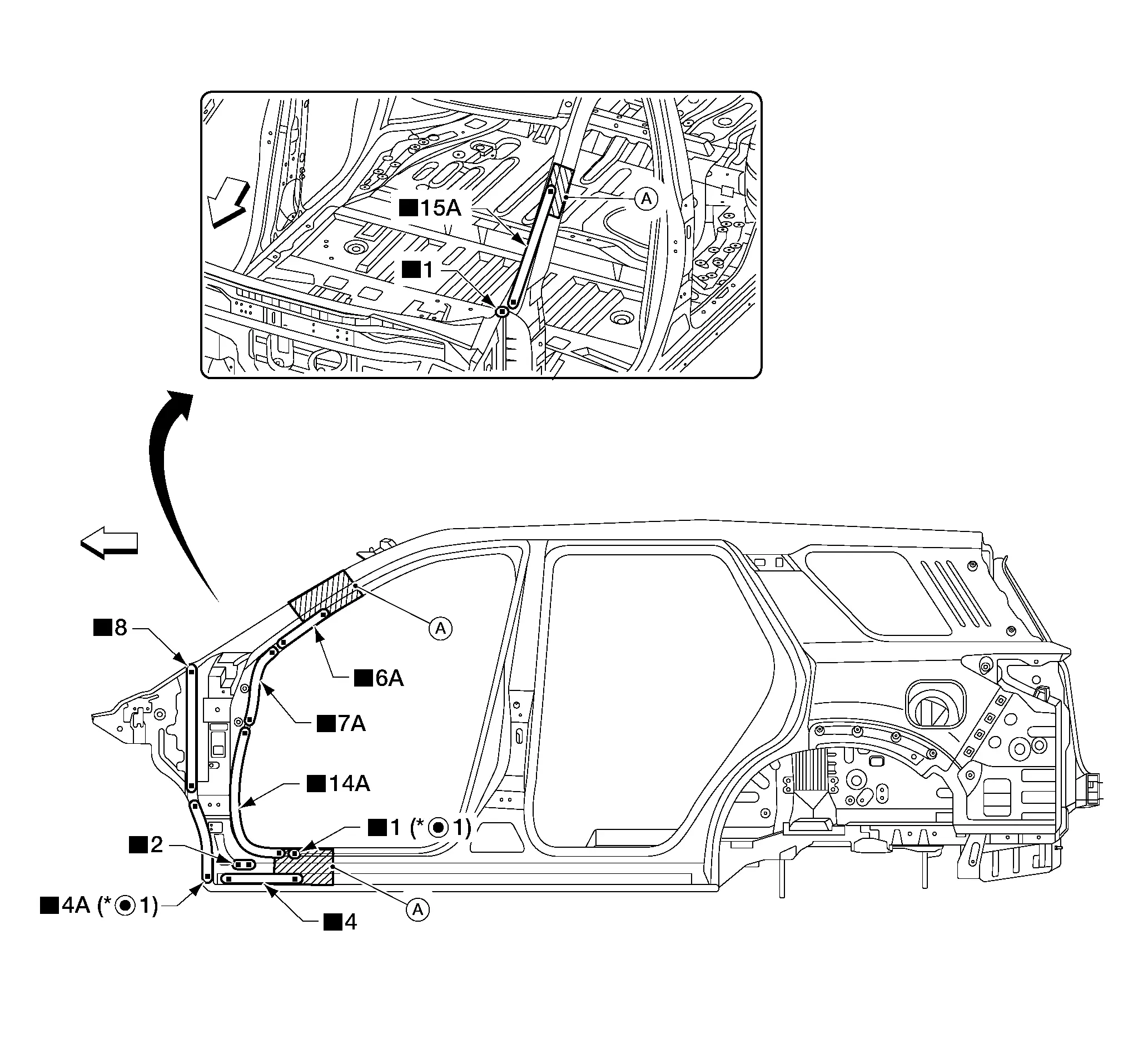
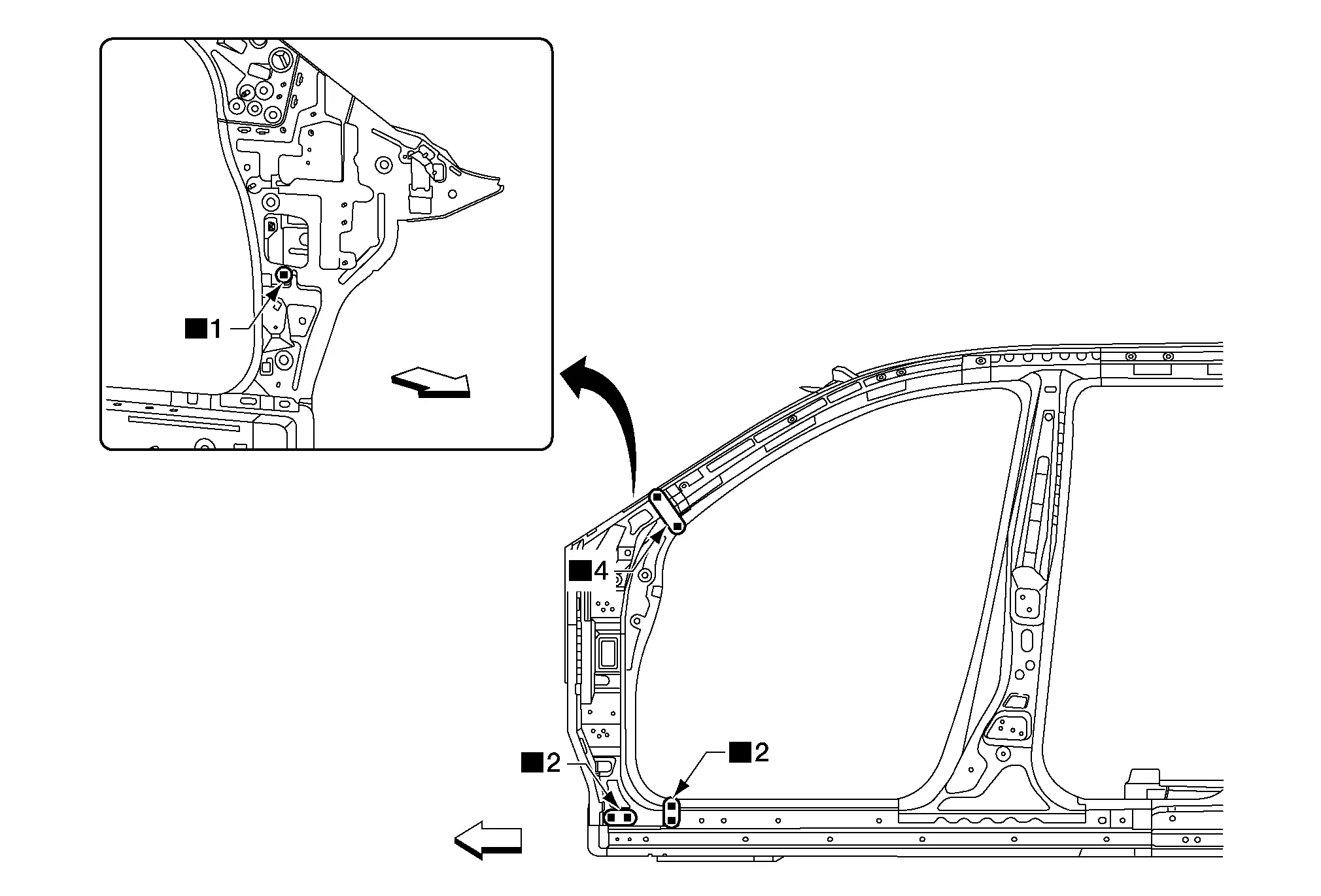
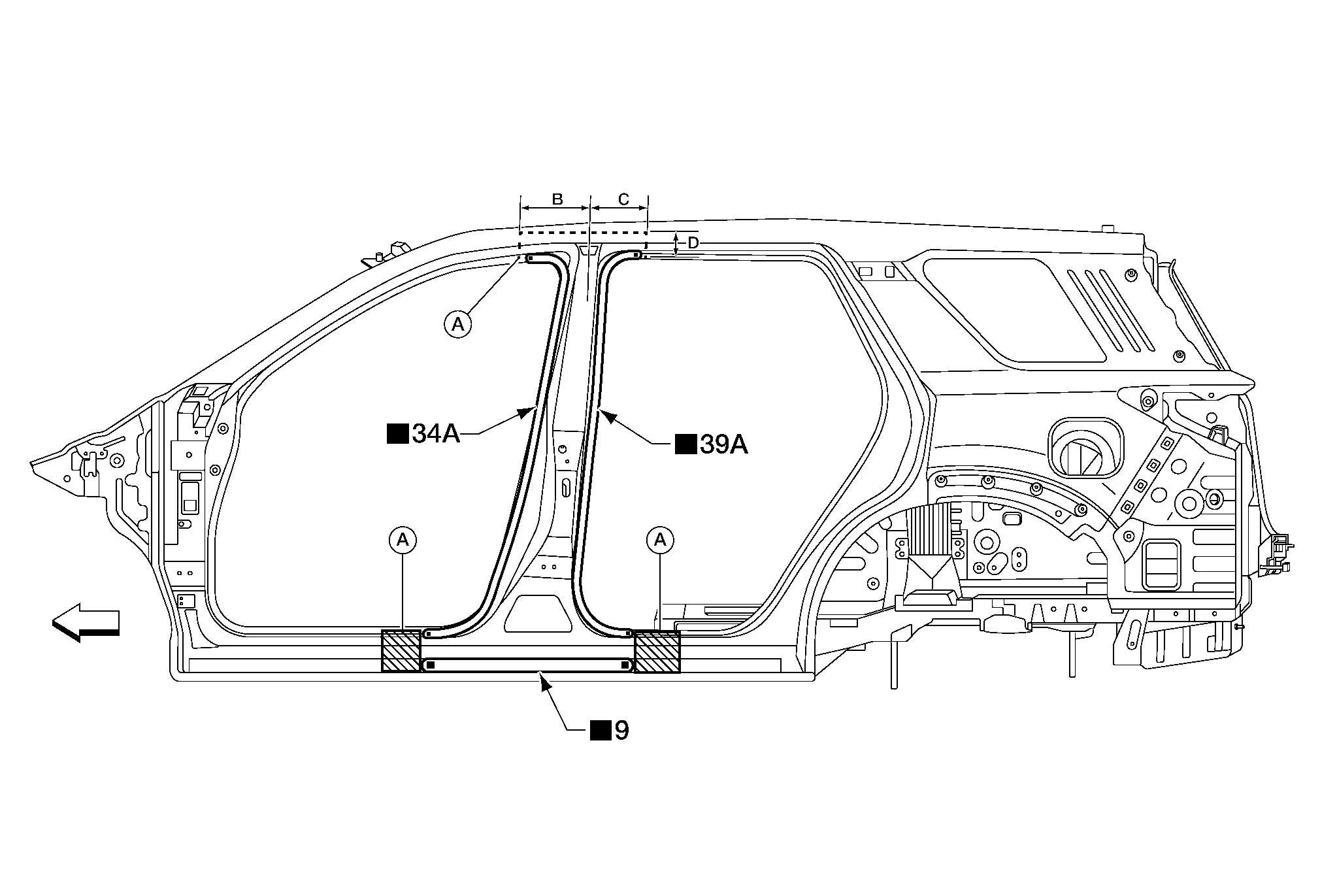
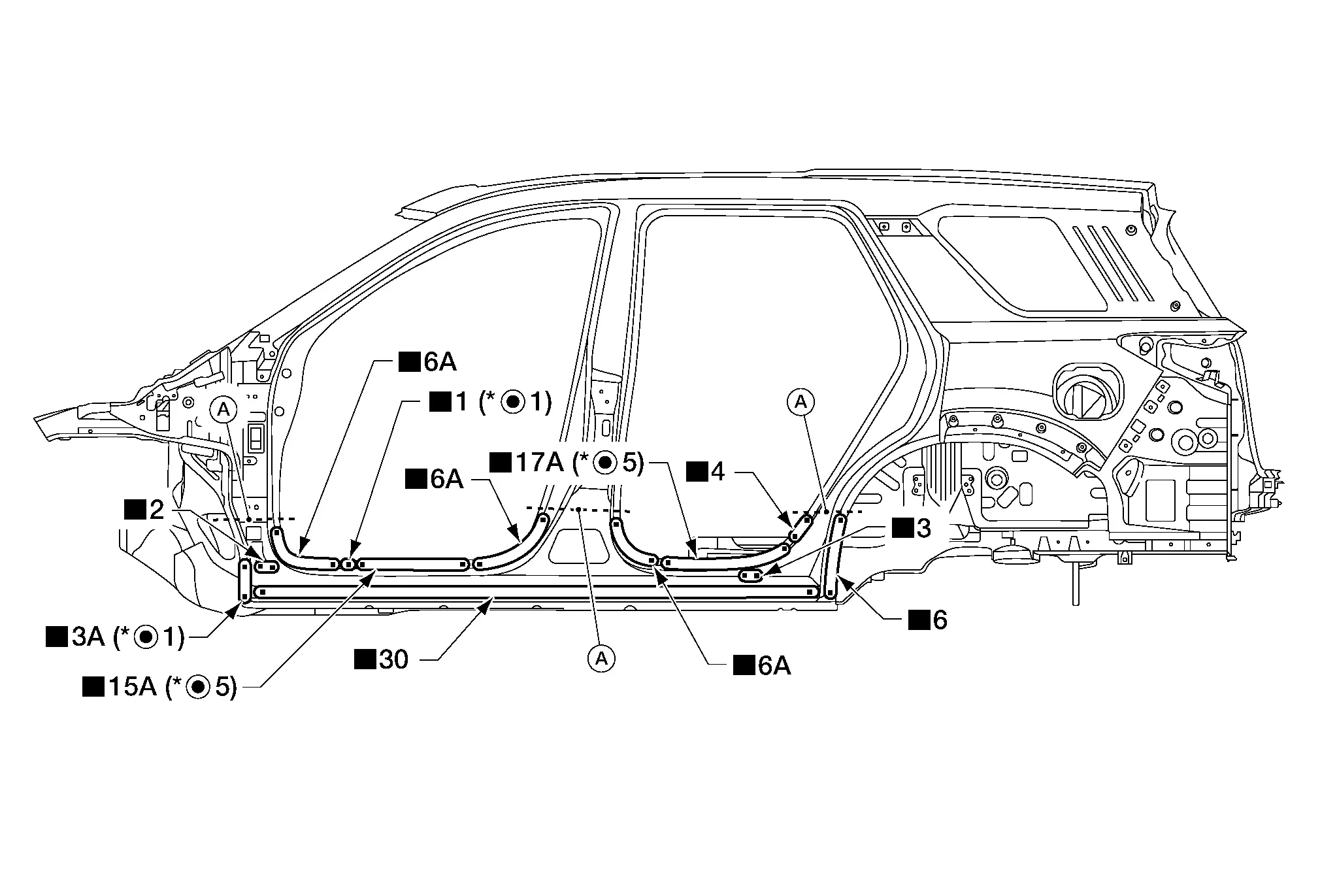
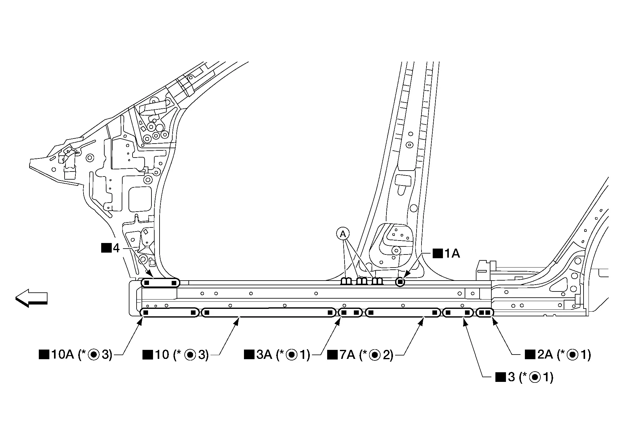
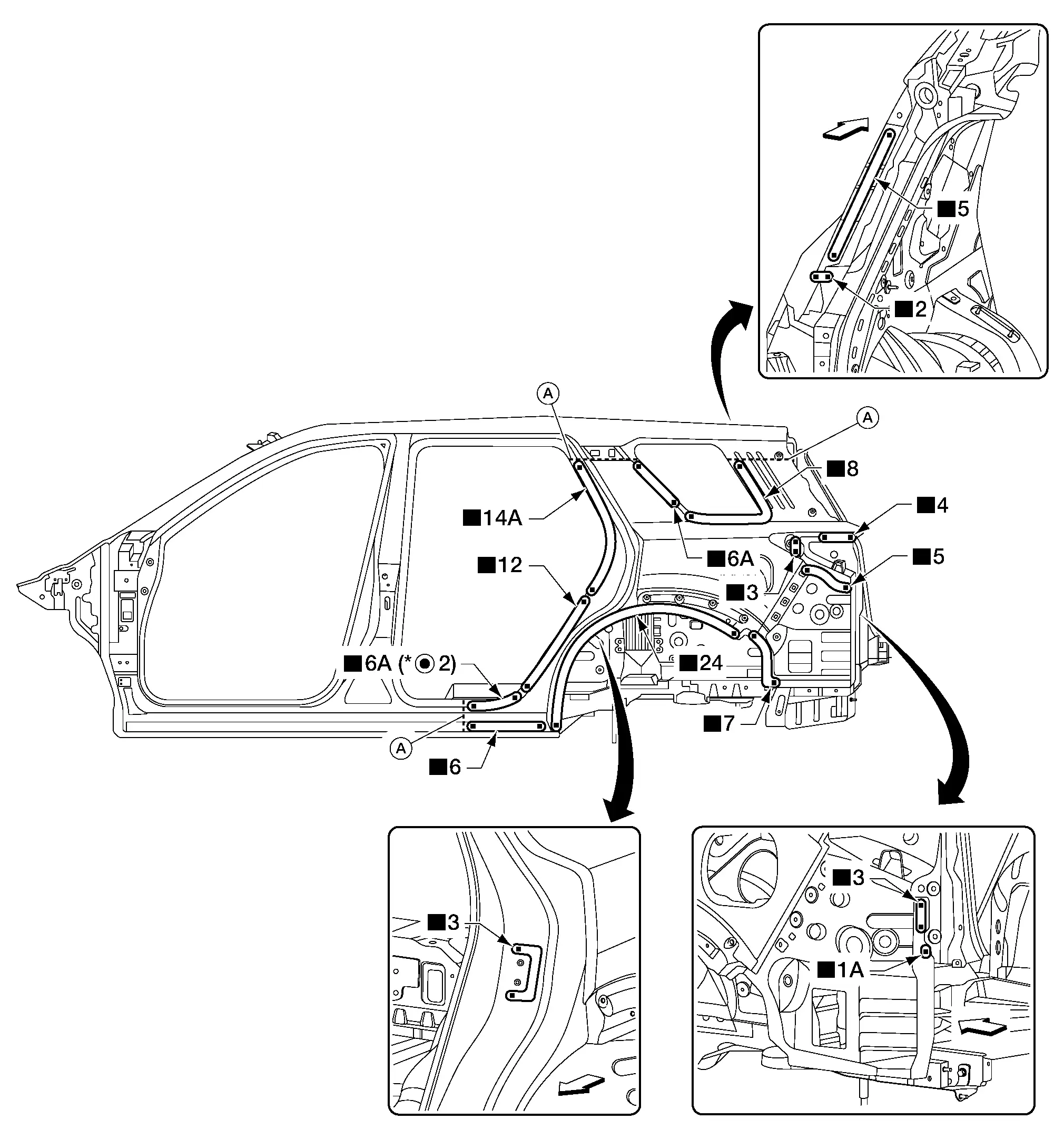
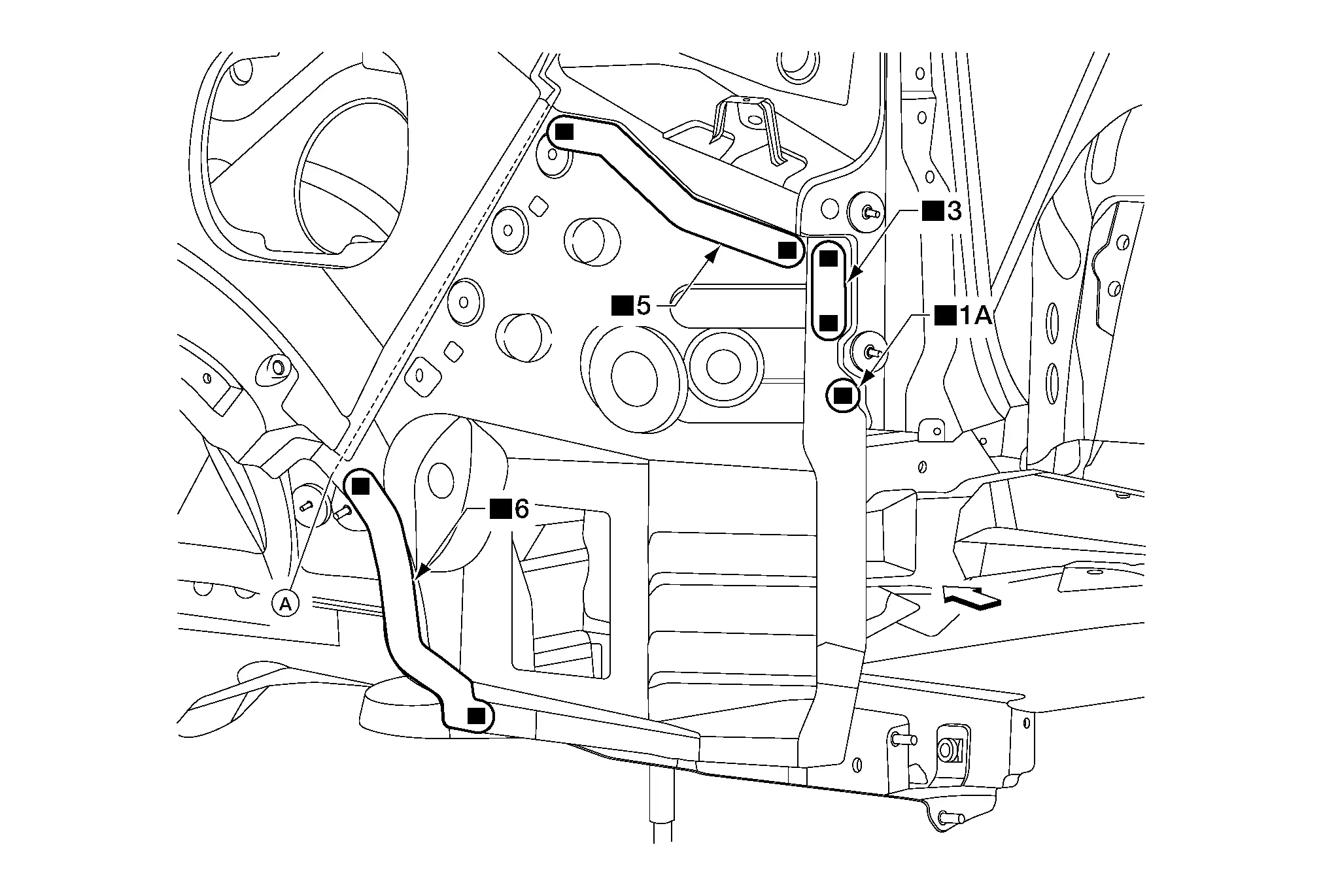
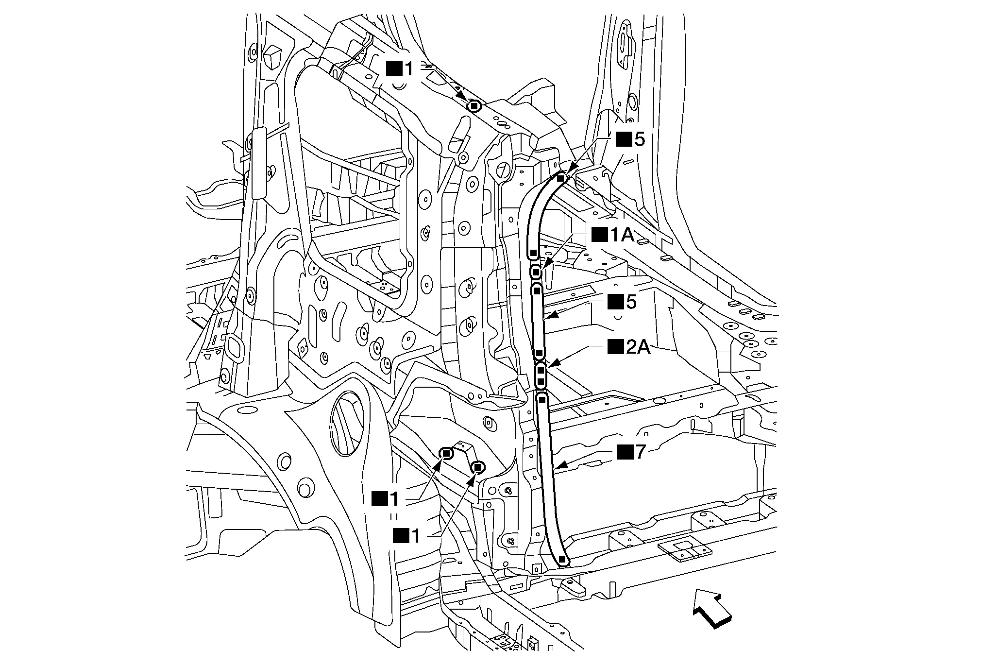
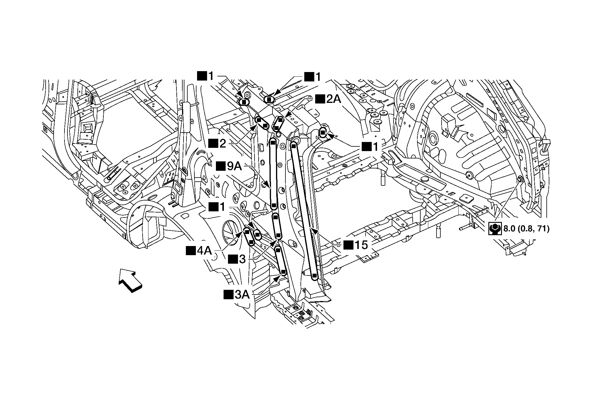
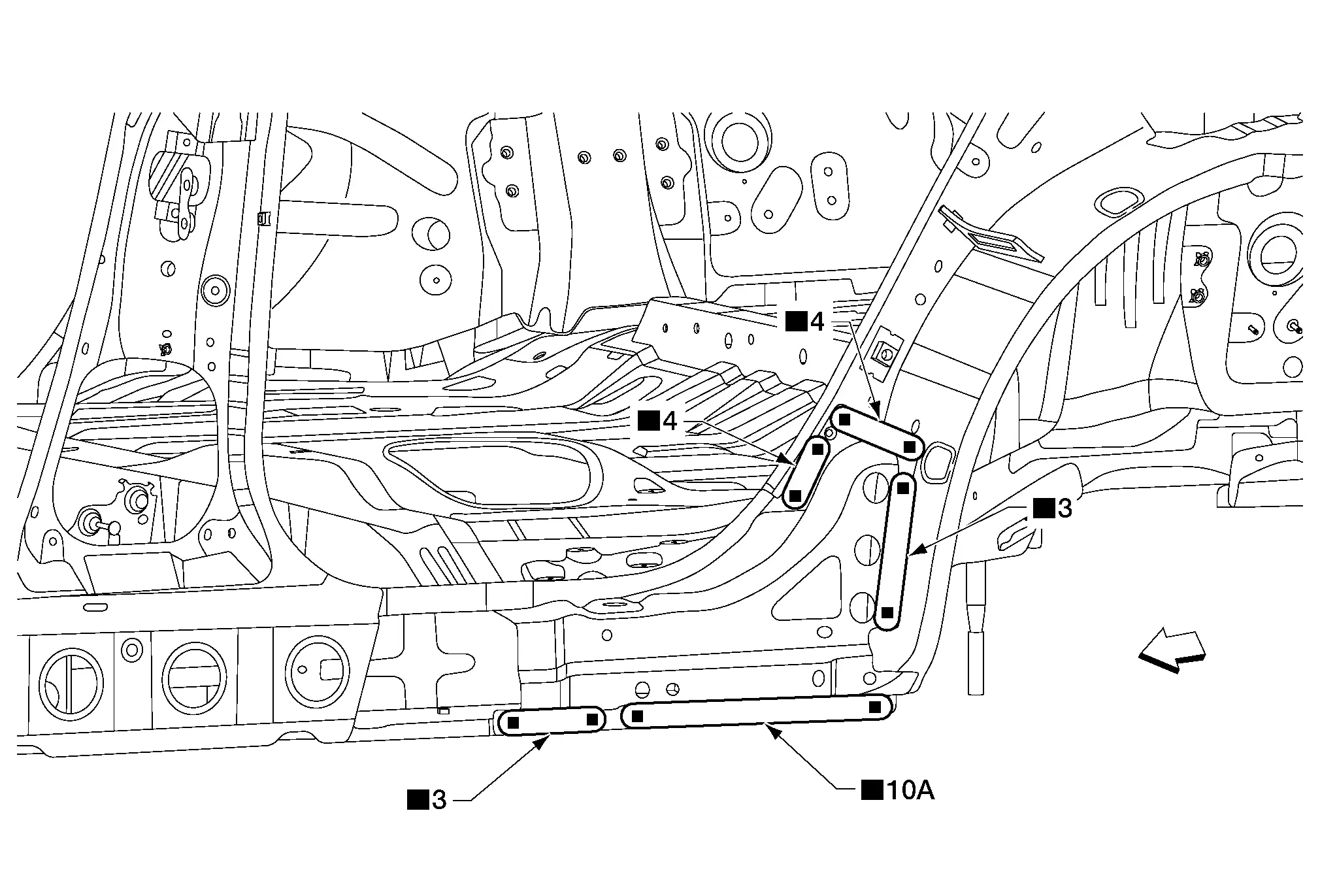
The following figure shows the areas which are sealed at the factory. Sealant which has been applied to these areas should be smooth and free from cuts or gaps. Care should be taken not to apply an excess amount of sealant and not to allow other unaffected parts to come into contact with the sealant.
 |
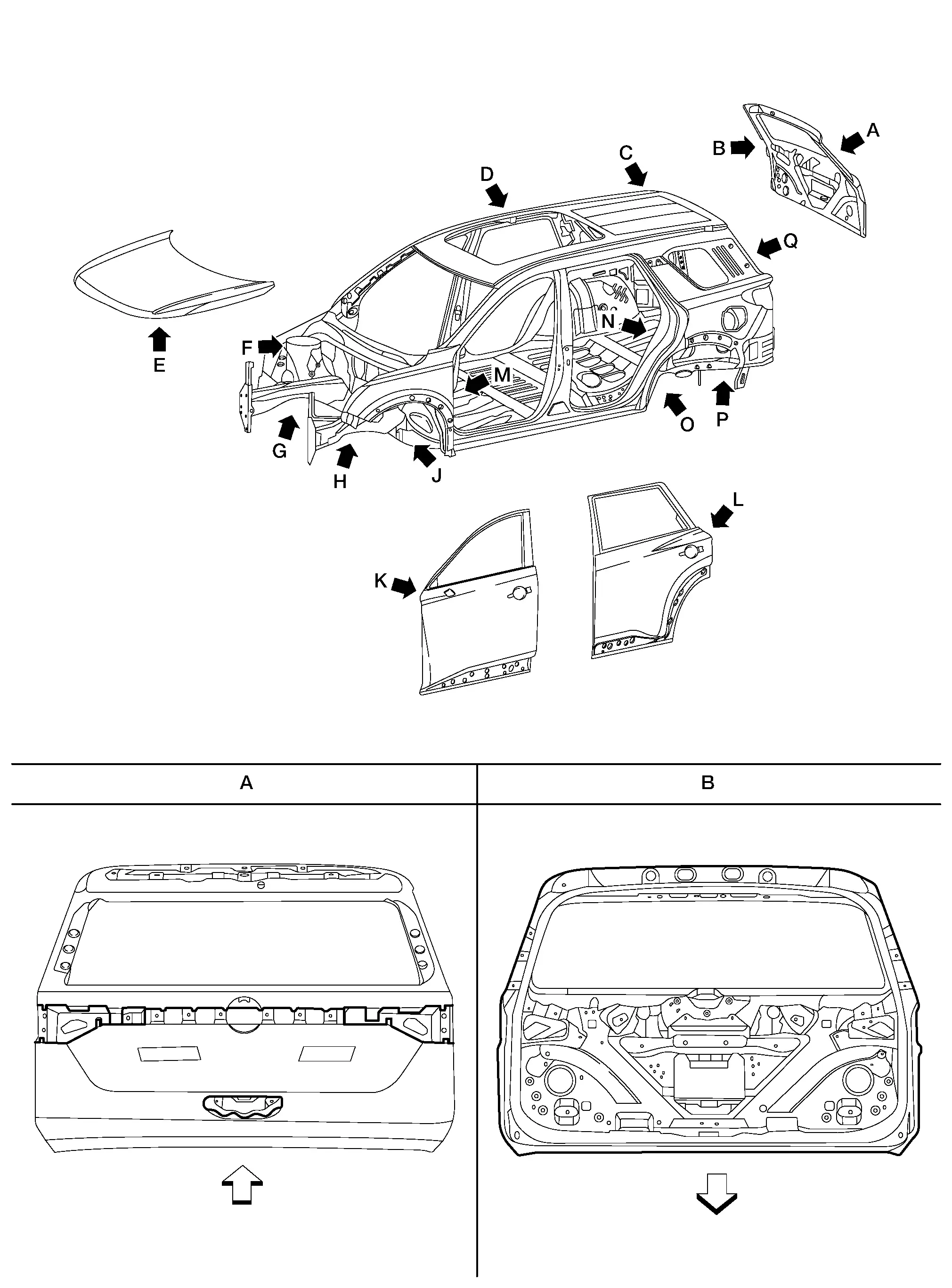
Front | ||||
| C. | Roof (without panoramic roof glass) shown; roof (with panoramic roof glass) similar | ||||||
 . . |
Front | ||||||
 |
Front | ||||
 |
Front | ||||
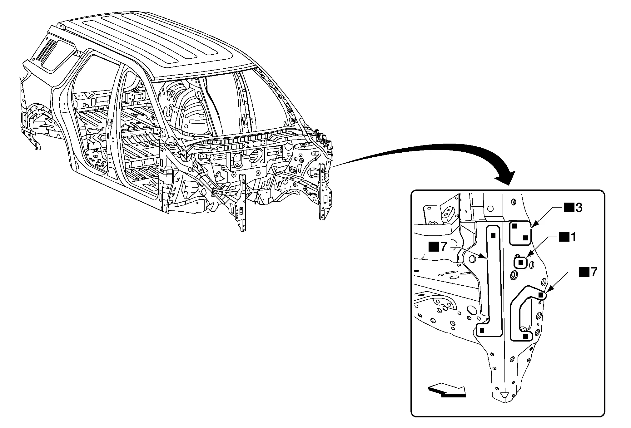
Body Construction Nissan Pathfinder R53
Body Construction
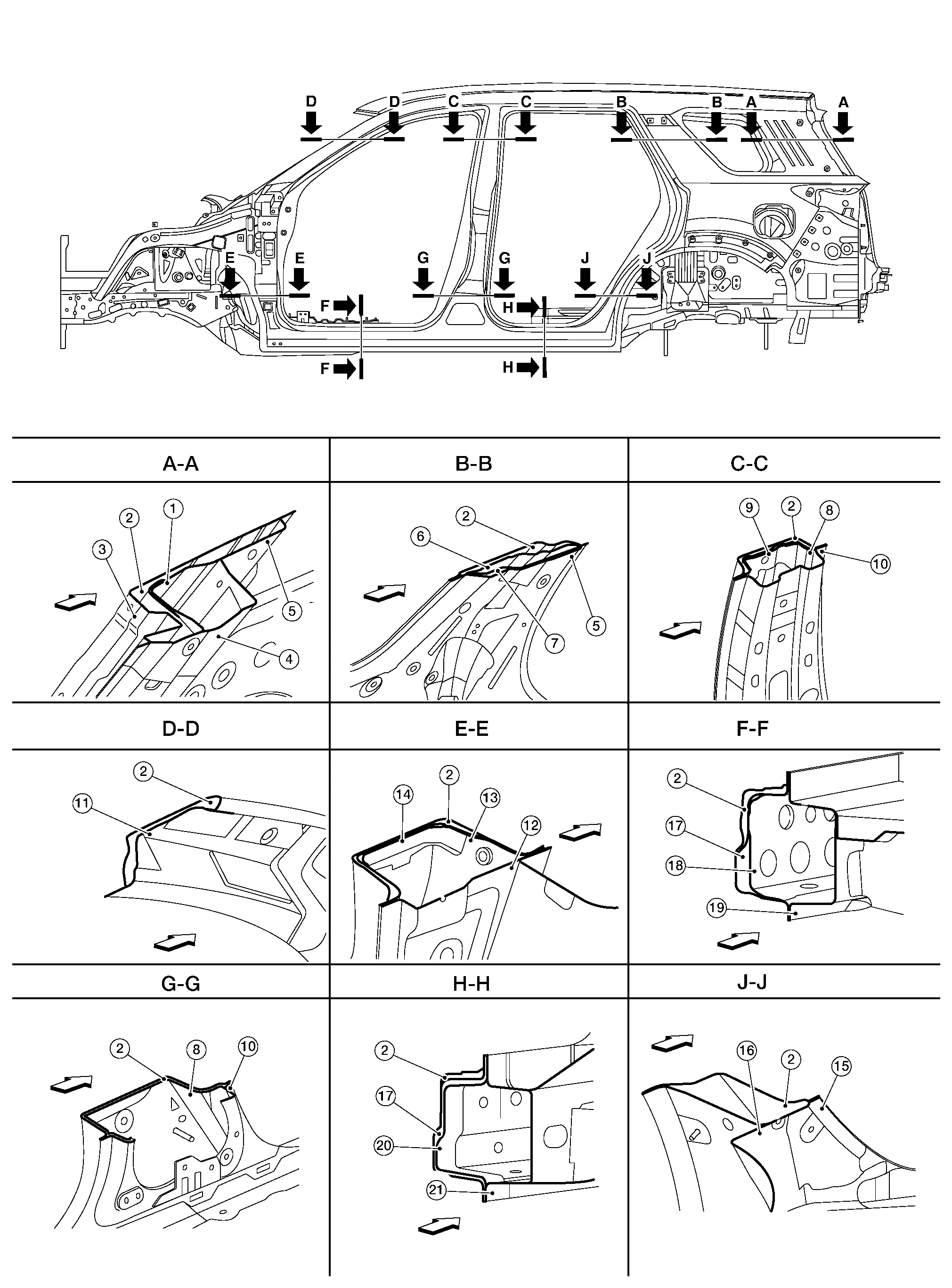
| 1. | Back pillar upper reinforcement | 2. | Body side outer | 3. | Back pillar |
| 4. | Rear roof rail brace | 5. | Rear pillar inner | 6. | Rear pillar inner reinforcement |
| 7. | Rear pillar seatbelt anchor | 8. | Center pillar reinforcement | 9. | Center pillar outer reinforcement |
| 10. | Center pillar inner | 11. | Front pillar upper reinforcement | 12. | Dash side |
| 13. | Front pillar upper hinge brace | 14. | Lower hinge plate | 15. | Rear wheelhouse inner |
| 16. | Rear wheelhouse outer | 17. | Sill outer reinforcement | 18. | Sill outer reinforcement inner |
| 19. | Sill inner reinforcement | 20. | Sill outer reinforcement rear | 21. | Sill inner extension |
 |
Front |
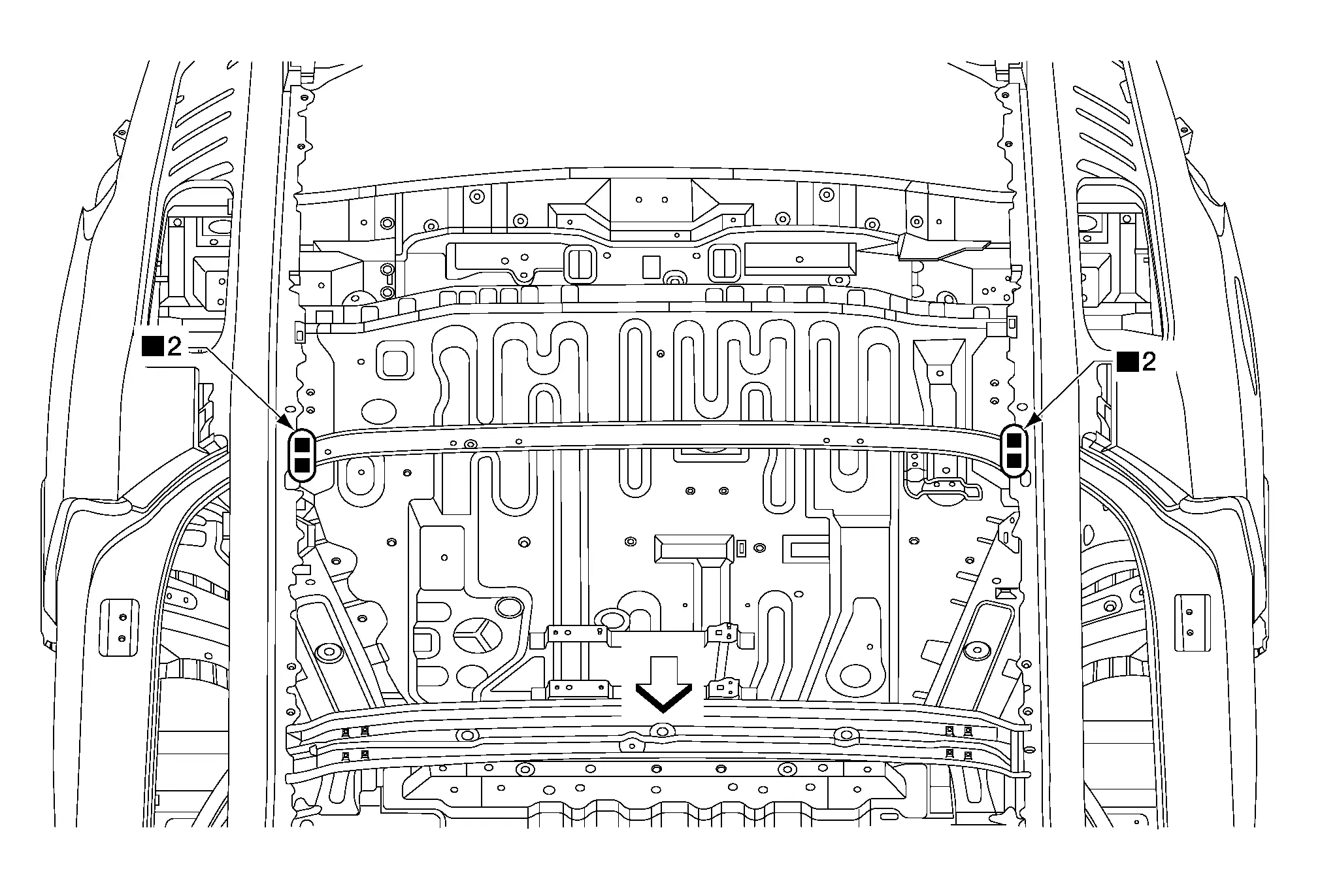
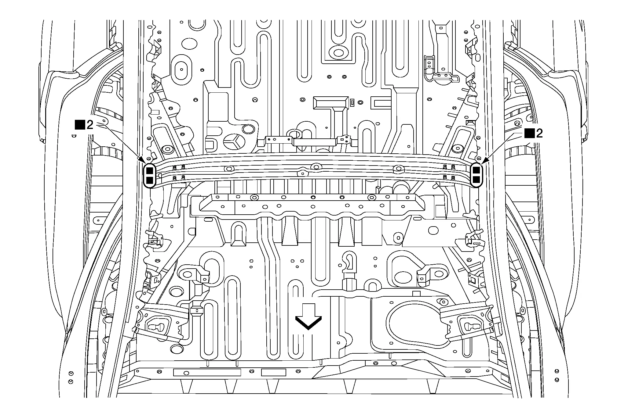
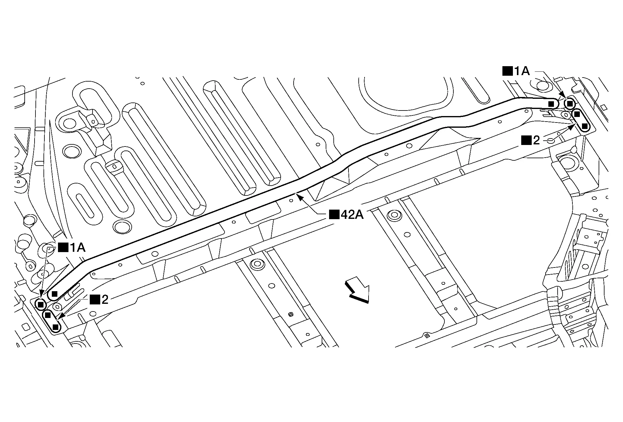
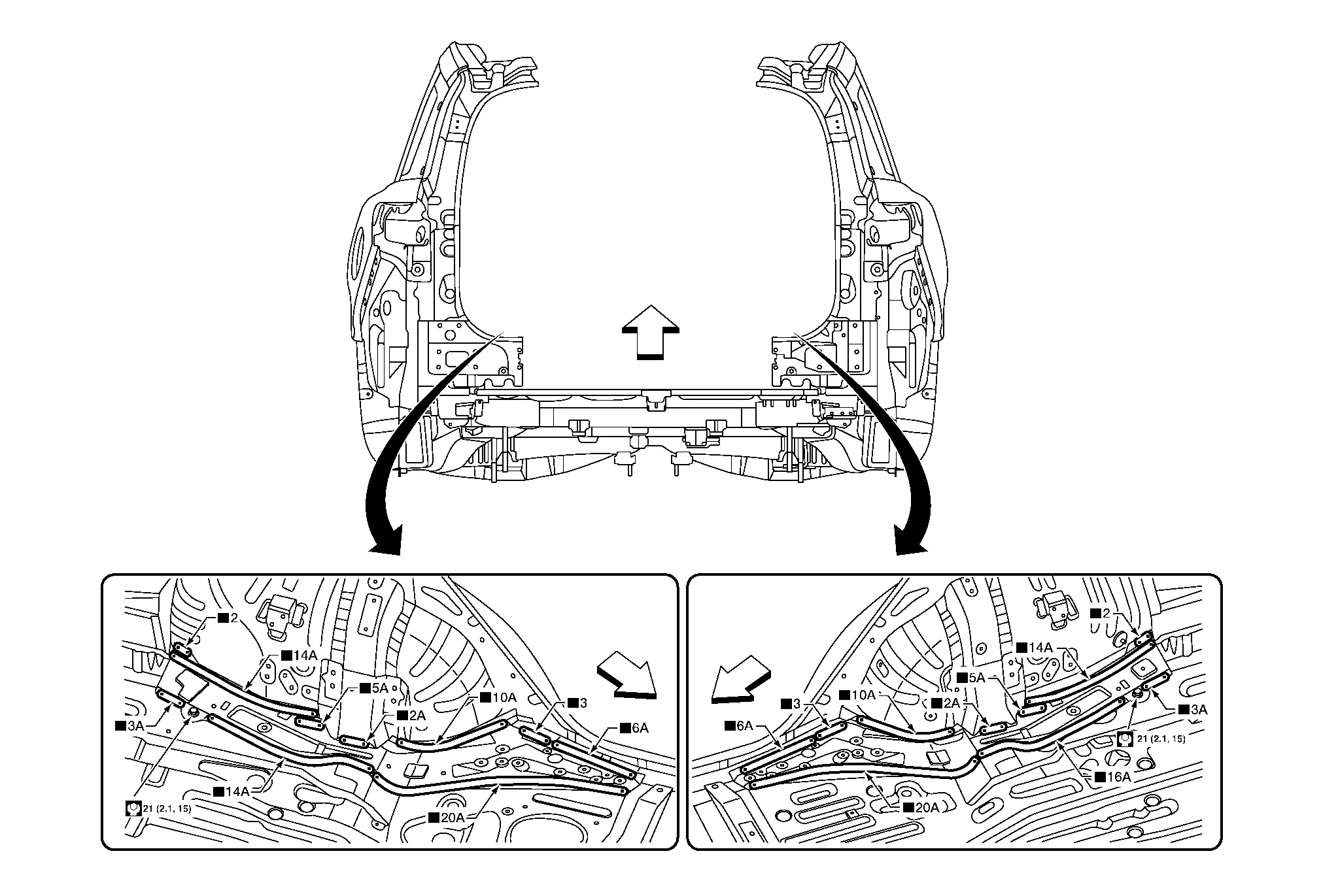
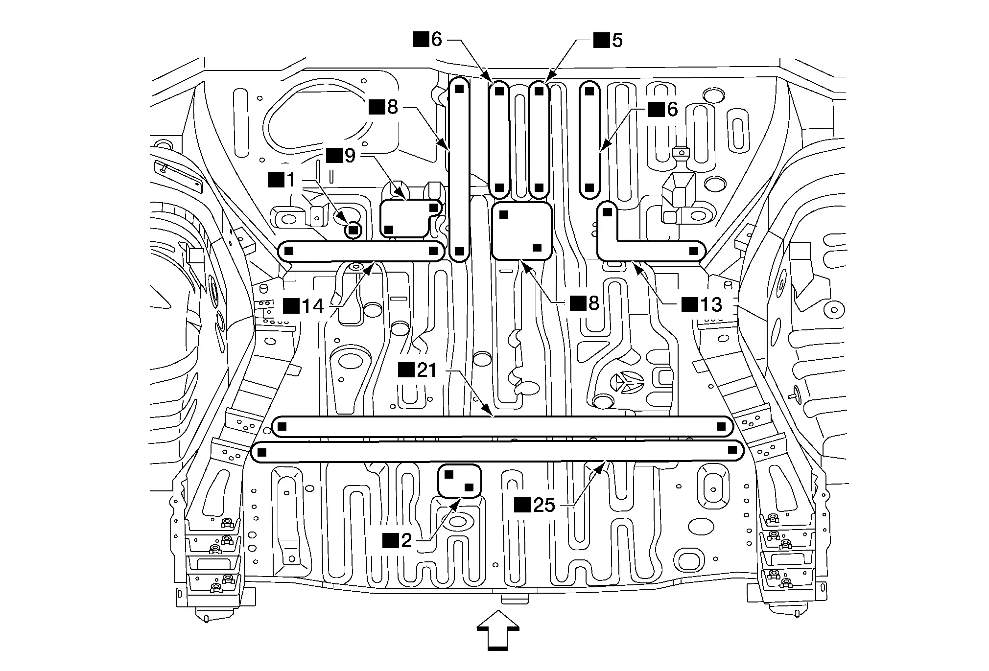
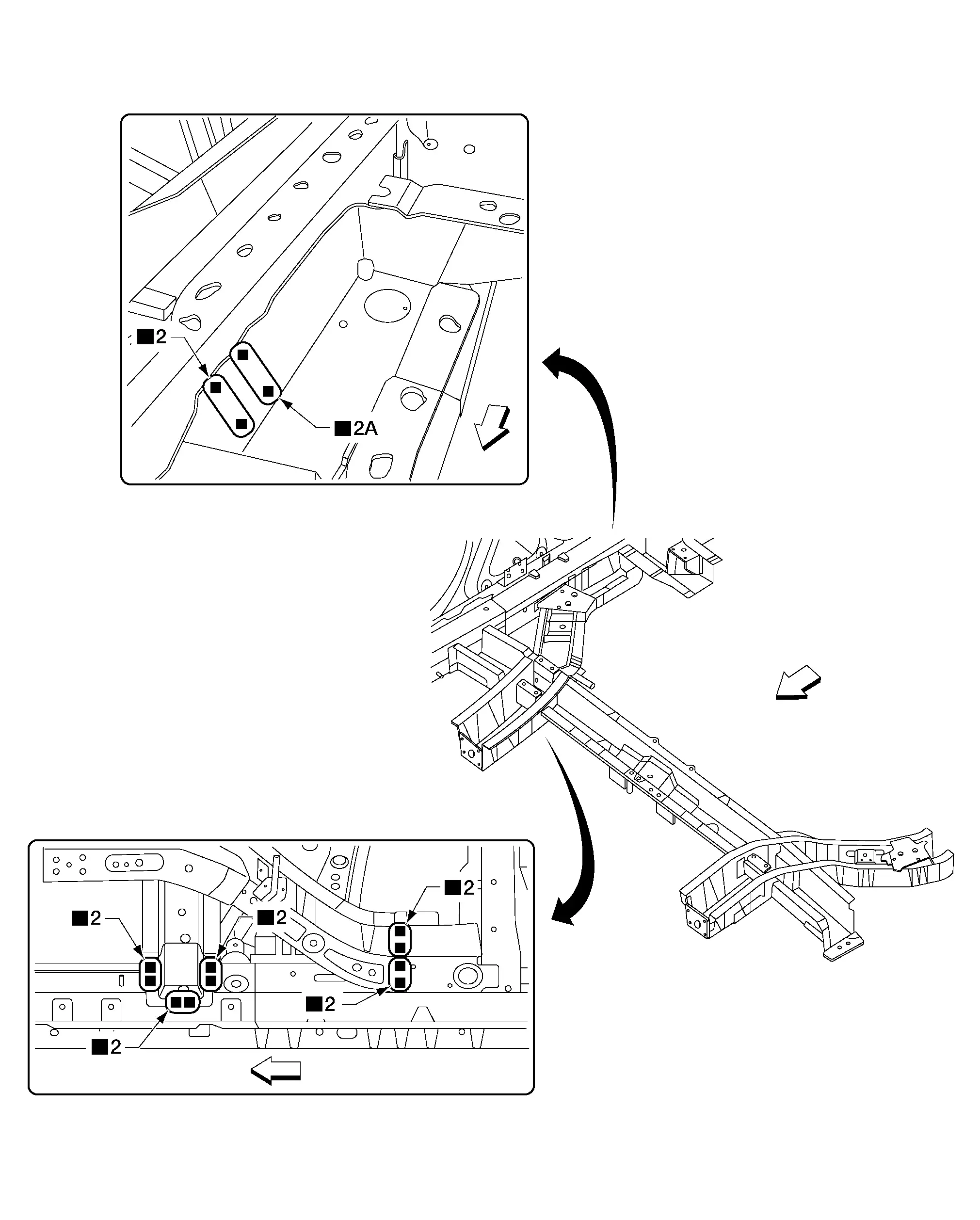
Fusible Insulator Applying Part
 NOTE:
NOTE:
Service replacement fusible insulator material is available in varying thickness. Always check with the Parts Department for the latest parts information.
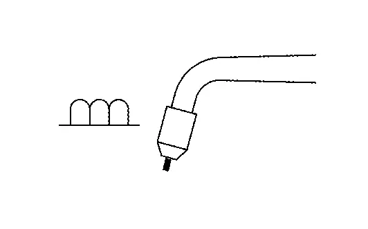
Apply the fusible insulator to prevent road noise, vibration and exhaust system heat inside the vehicle.
The service replacement material is cut-to-fit and not supplied in the same shape as original factory installed fusible insulator.
Place the fusible insulators in the positions shown in the figure and properly affix them to the vehicle surface.
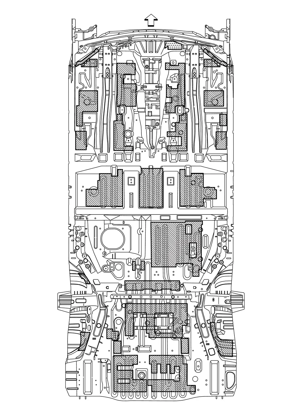
Unit: mm (in)
 |
: Nissan Pathfinder Vehicle front |
 |
: Fusible insulator thickness 3.0 (0.12) |
 |
: Fusible insulator thickness 3.7 (0.15) |
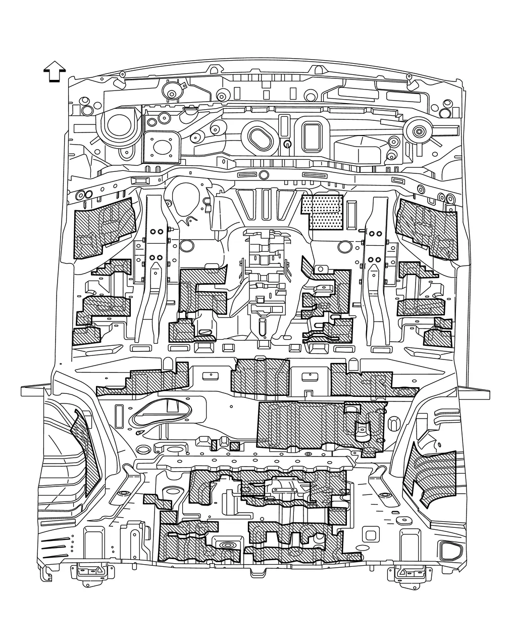
Unit: mm (in)
 |
: Nissan Pathfinder Vehicle front |
 |
: Fusible insulator thickness 3.0 (0.12) |
 |
: Fusible insulator thickness 3.7 (0.15) |
Replacement Operations Nissan Pathfinder 5th Gen
Precautions for Body Repair
WARNING:
-
The repair information in this section is intended for trained body repair technicians who have attained a high level of skill and experience (e.g. ASE Collision Repair Certification, I-CAR Professional Development Program [PDP] training, etc.) in repairing collision damaged Nissan Pathfinder vehicles using appropriate tools and equipment. Performing repairs without the proper training, tools or equipment could damage the Nissan Pathfinder vehicle or cause personal injury or death to you or others.
-
The information in this Body Repair Manual is a guideline for repairing collision damaged Nissan Pathfinder vehicles. However, this information cannot cover all possible ways that a vehicle can be damaged. As such, the body repair technician is responsible for making sure that the repair does not affect the structural integrity or safety of the Nissan Pathfinder vehicle. Improper repair of a damaged vehicle may result in a collision, property damage, personal injury or death.
-
Nissan recommends using only new genuine Nissan replacement body parts. Use of used, salvaged or aftermarket body parts is not recommended by Nissan. Non-genuine Nissan components may affect the Nissan Pathfinder vehicle's structural integrity and crash safety performance, which could result in serious personal injury or death in an accident.
Description
-
Technicians are encouraged to read the Body Repair Manual (Fundamentals) in order to ensure that the original functions and quality of the Nissan Pathfinder vehicle are maintained. The Body Repair Manual (Fundamentals) contains additional information, including cautions and warnings, that are not included in this manual. Technicians should refer to both manuals to ensure proper repair.
-
Please note that this information is prepared for worldwide usage, and as such, certain procedures might not apply in some regions or countries.
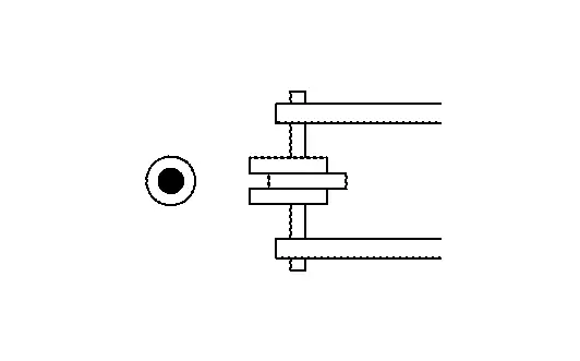
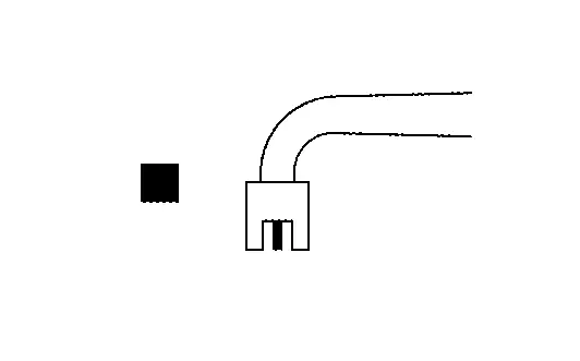
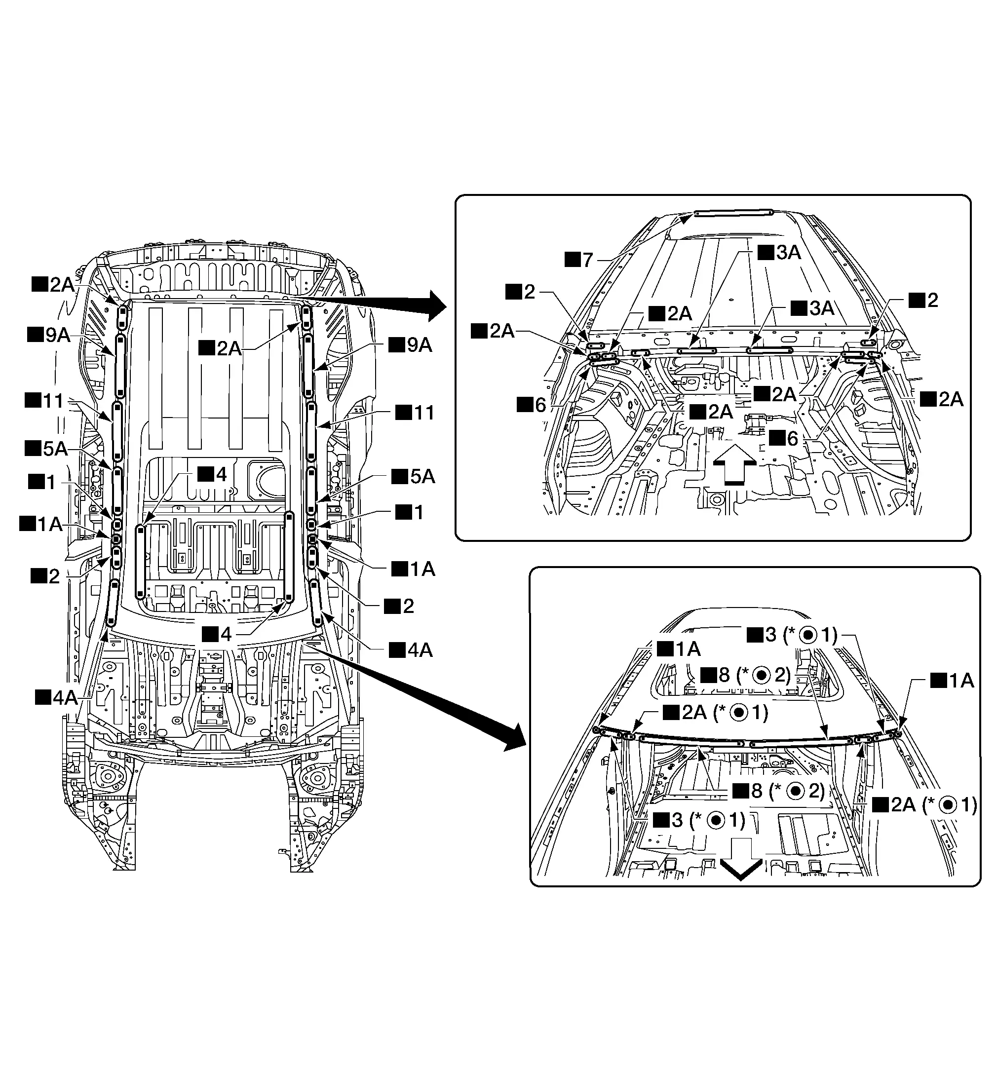
The symbols used in this section for welding operations are shown below.
| Symbol marks | Description | |
|---|---|---|
| "Number" |
"Number" after symbol mark is the total number of welds to apply. Example 1: ■"4"A = 4 MAG plug welds for 3-panel plug weld method. Example 2: "1" x20 (0.79) = 1 MAG seam weld by length 20 mm (0.79 in). "1" x20 (0.79) = 1 MAG seam weld by length 20 mm (0.79 in). |
|
|
|
2-panel spot weld |
|
|
|
3-panel spot weld | |
|
|
MAG plug weld |
|
|
For 3-panel plug weld method
|
||
|
|
MAG seam weld / Point weld |
|
|
|
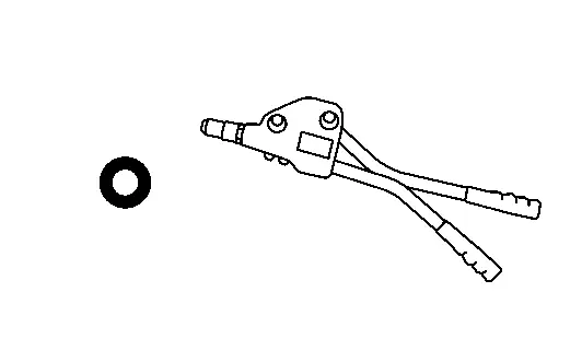
Rivet |
|
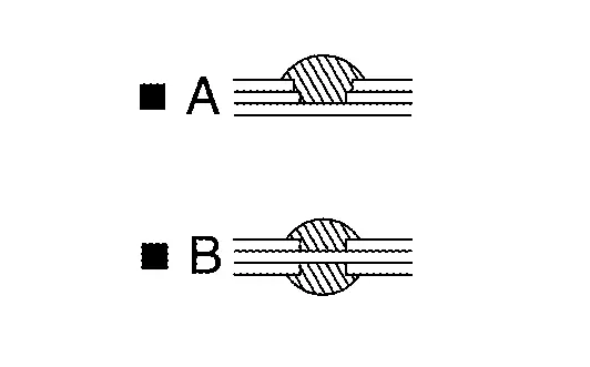

-
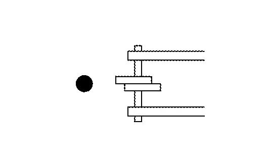
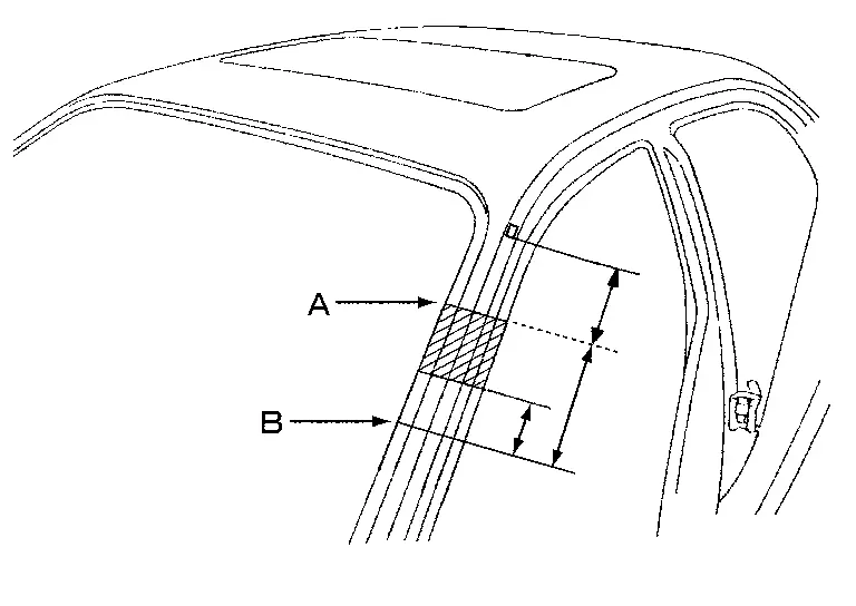
Front pillar butt joint can be determined anywhere within shaded area as shown in the figure. The best location for the butt joint is at position A due to the construction of the Nissan Pathfinder vehicle.
-
Determine cutting position and record distance from the locating indent. Use this distance when cutting the service part. Cut outer front pillar over 60 mm (2.36 in) above the inner front pillar cut position.
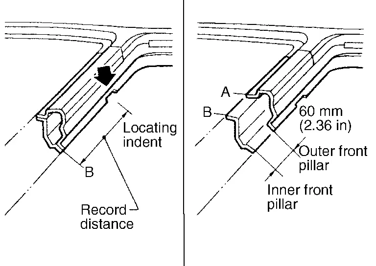
-
Prepare a cutting jig to make outer pillar easier to cut. Also, this will permit the service part to be accurately cut at the joint position.
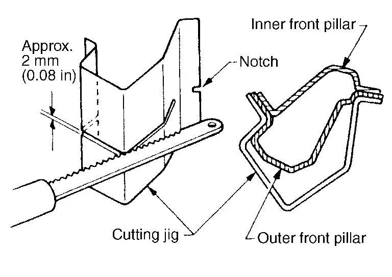
-
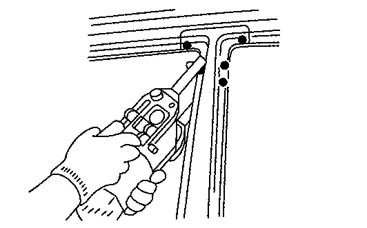
An example of cutting operation using a cutting jig is as per the following.
-
Mark cutting lines.
A: Cut position of outer pillar
B: Cut position of inner pillar
-
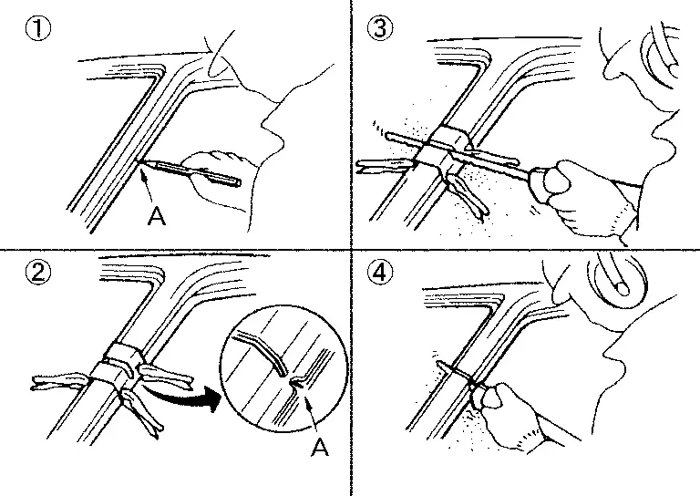
Align cutting line with notch on jig. Clamp jig to pillar.
-
Cut outer pillar along groove of jig (at position A).
-
Remove jig and cut remaining portions.
-
Cut inner pillar at position B in same manner.
Roof
ROOF (WITH PANORAMIC ROOF GLASS)
 |
Front | ||||
| Replacement parts | |||||
| • | Roof (with panoramic roof glass) | ||||
 |
For spot welding of steel plate of strength 980 MPa, observe the indicated welding conditions. Refer to Welding of Ultra High Strength Steel. | ||||
ROOF (WITHOUT PANORAMIC ROOF GLASS)
 |
Front | ||||
| Replacement parts | |||||
| • | Roof (without panoramic roof glass) | ||||
 |
For spot welding of steel plate of strength 980 MPa, observe the indicated welding conditions. Refer to Welding of Ultra High Strength Steel. | ||||
FRONT ROOF RAIL
Work after roof is removed.
 |
Front | ||||
| Replacement parts | |||||
| • | Front roof rail | ||||
REAR ROOF RAIL
Work after roof is removed.
 |
Front | ||||
| Replacement parts | |||||
| • | Rear roof rail | ||||
ROOF BOW 5TH
Work after roof is removed.
 |
Front | ||||
| Replacement parts | |||||
| • | Roof bow 5th | ||||
ROOF BOW 4TH [ROOF (WITHOUT PANORAMIC ROOF GLASS) ONLY]
Work after roof is removed.
 |
Front | ||||
| Replacement parts | |||||
| • | Roof bow 4th | ||||
ROOF BOW 2ND [ROOF (WITHOUT PANORAMIC ROOF GLASS) ONLY]
Work after roof is removed.
 |
Front | ||||
| Replacement parts | |||||
| • | Roof bow 2nd | ||||
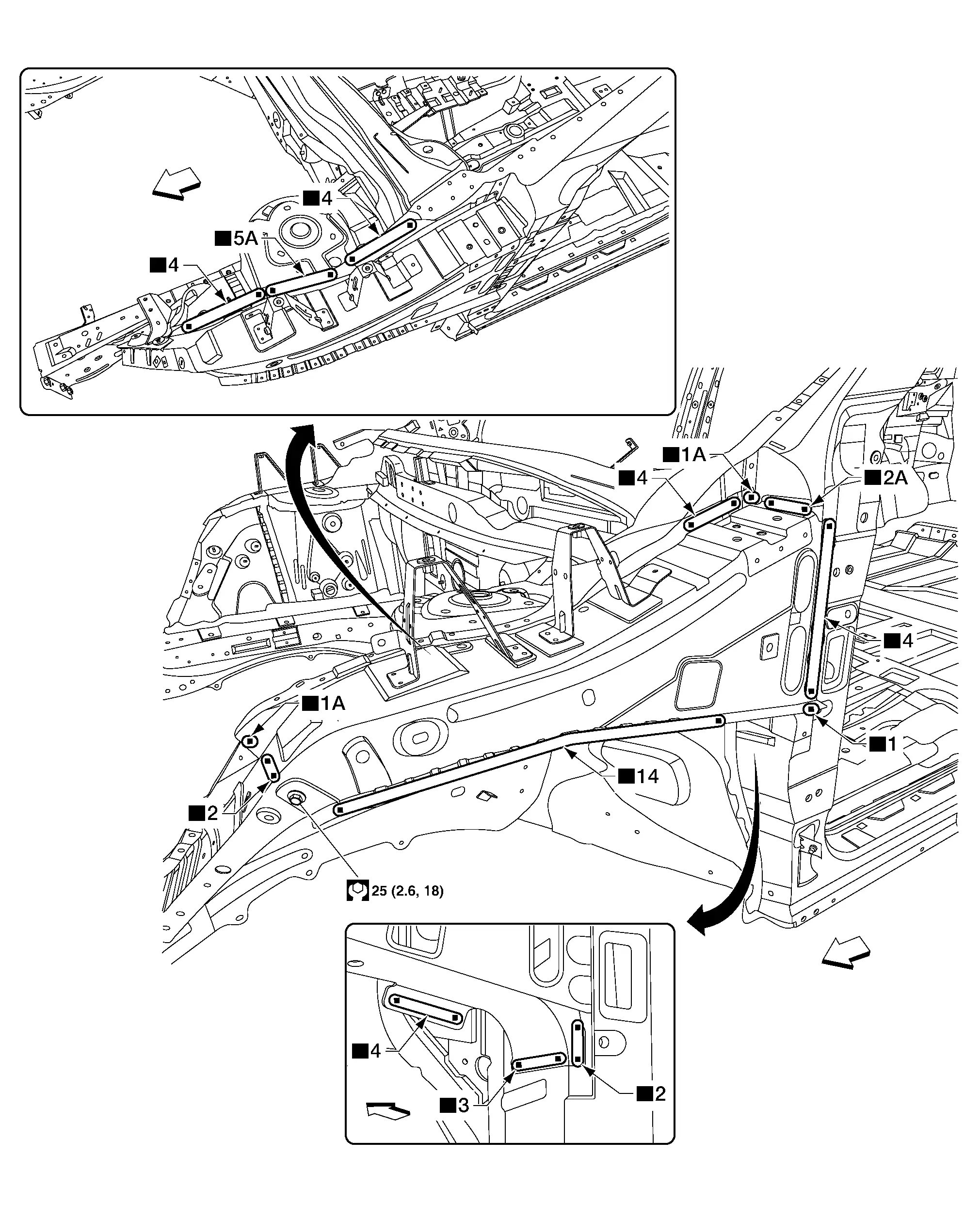
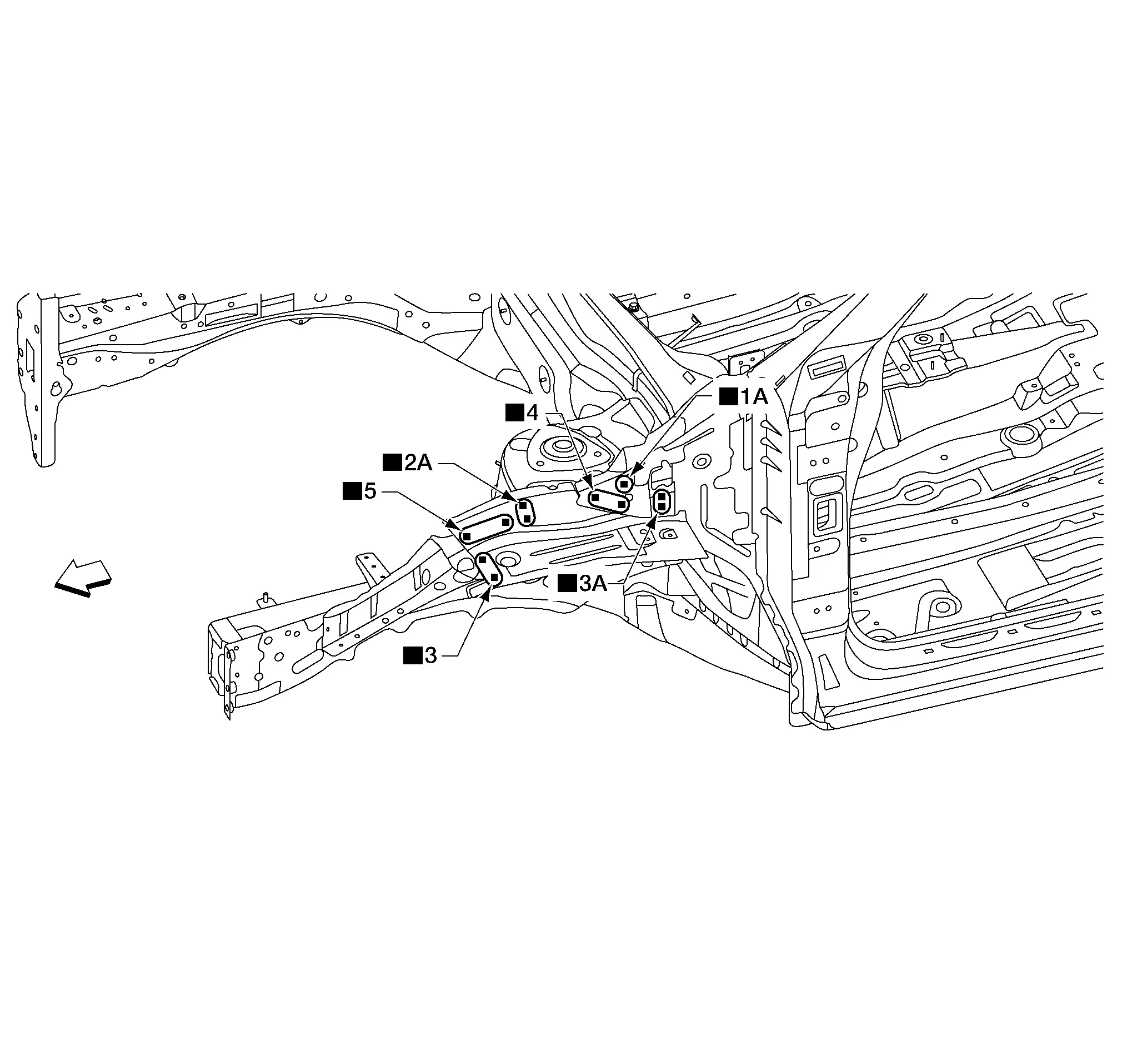
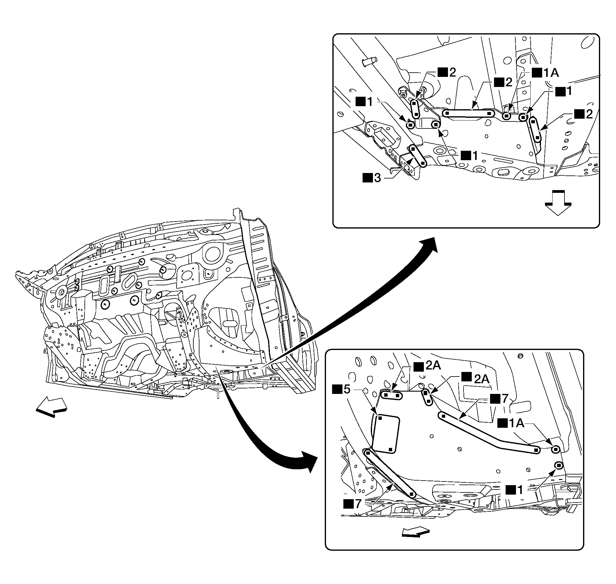
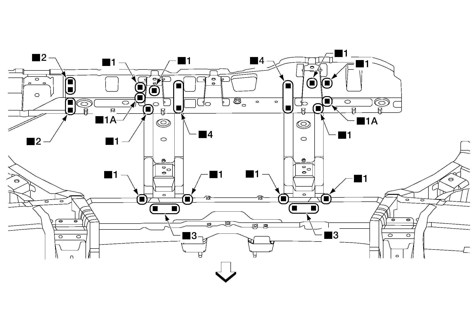
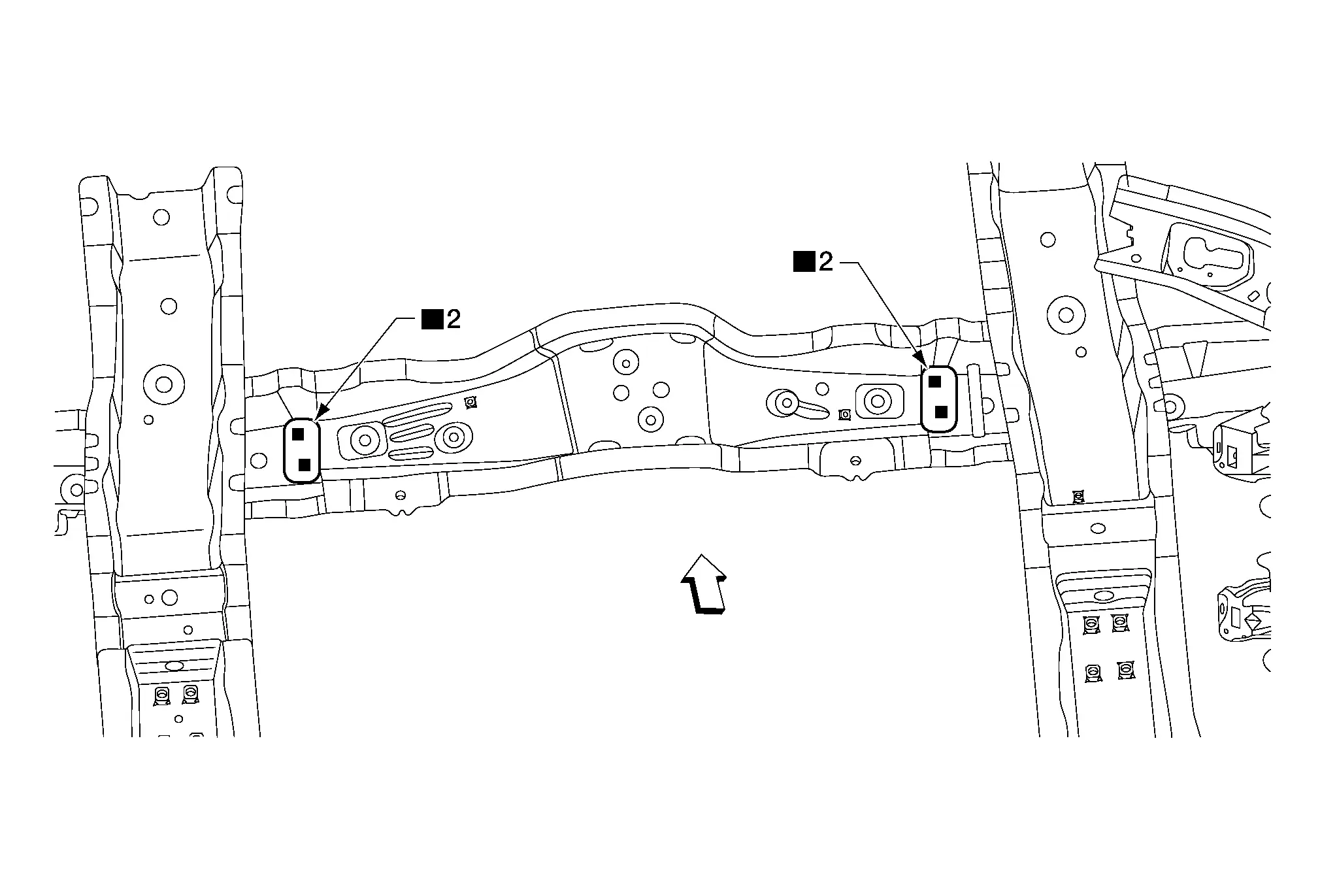
Front Side Member Connector
 |
Front | ||||
| Replacement parts | |||||
| • | Front side member connector | ||||
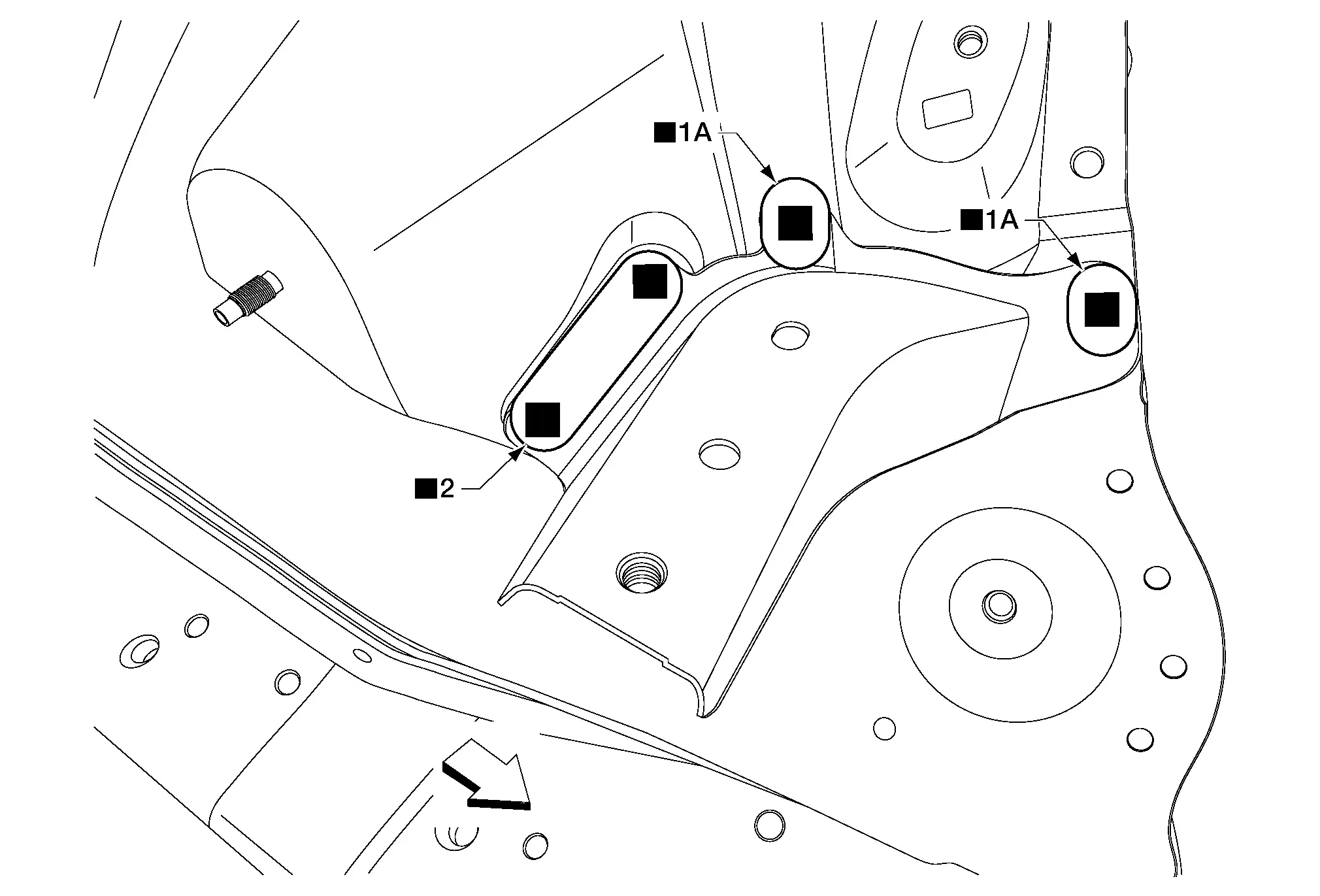
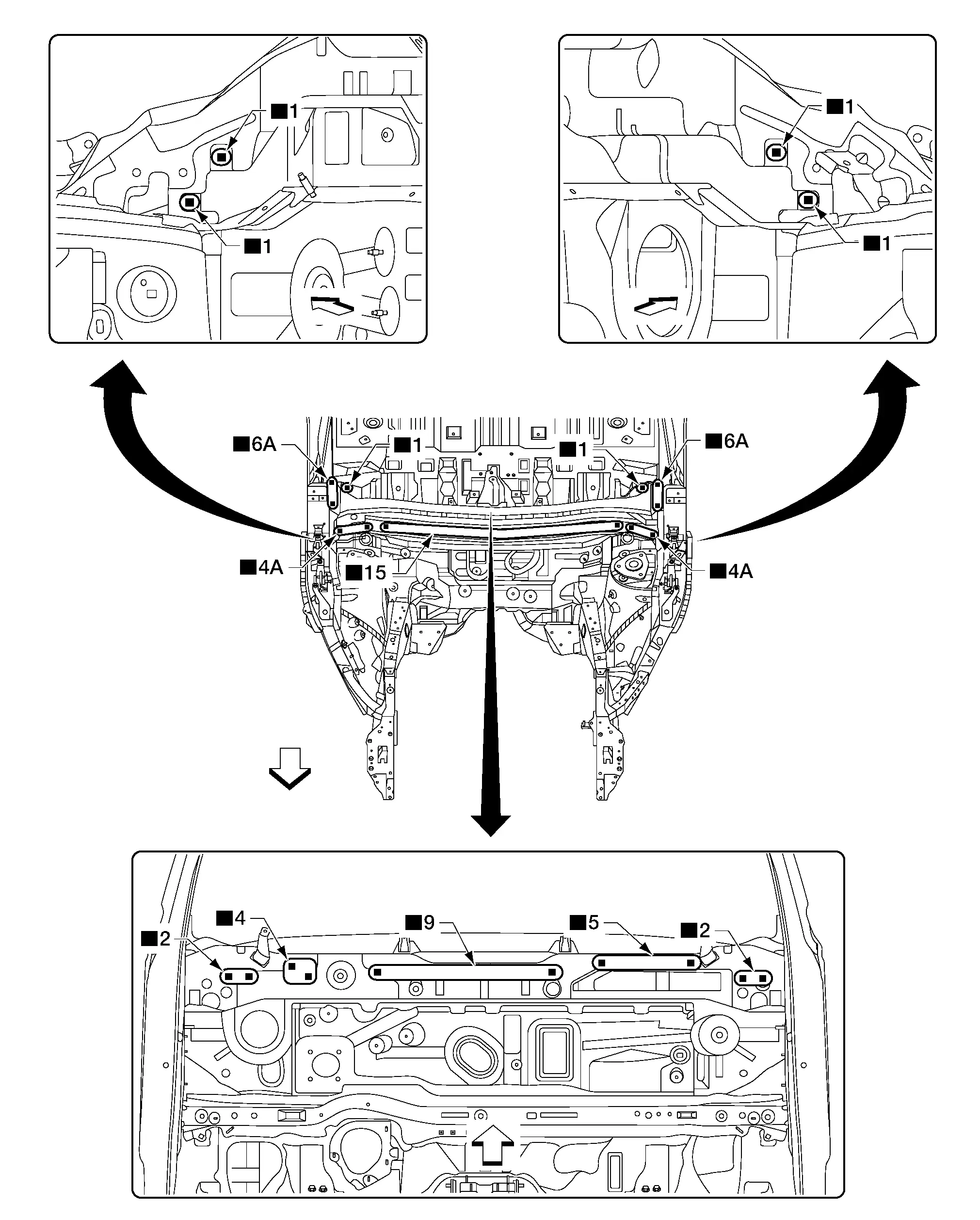
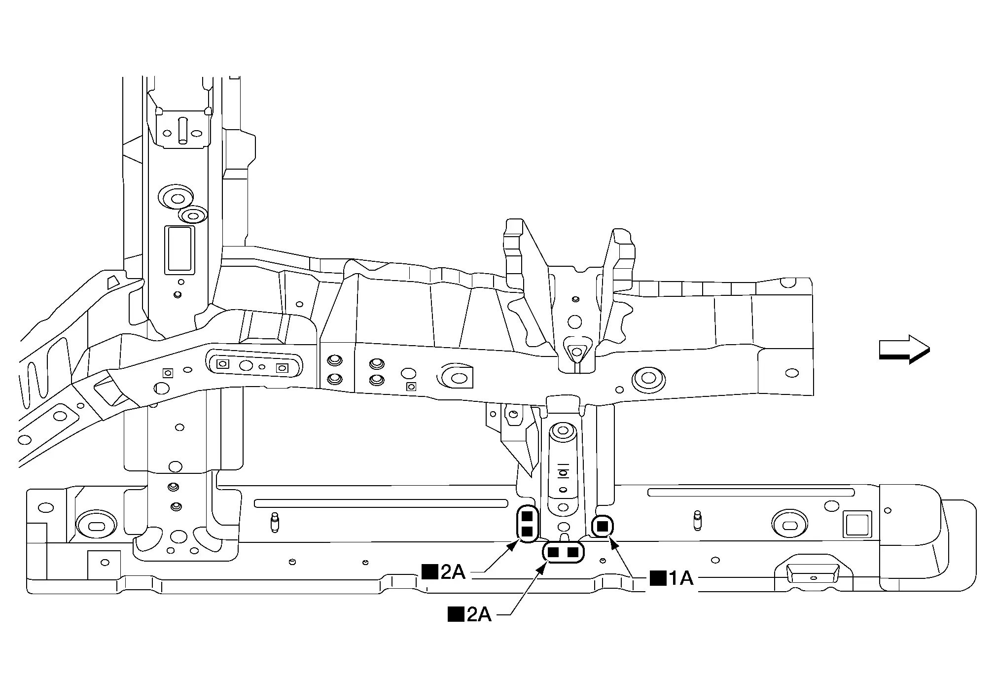
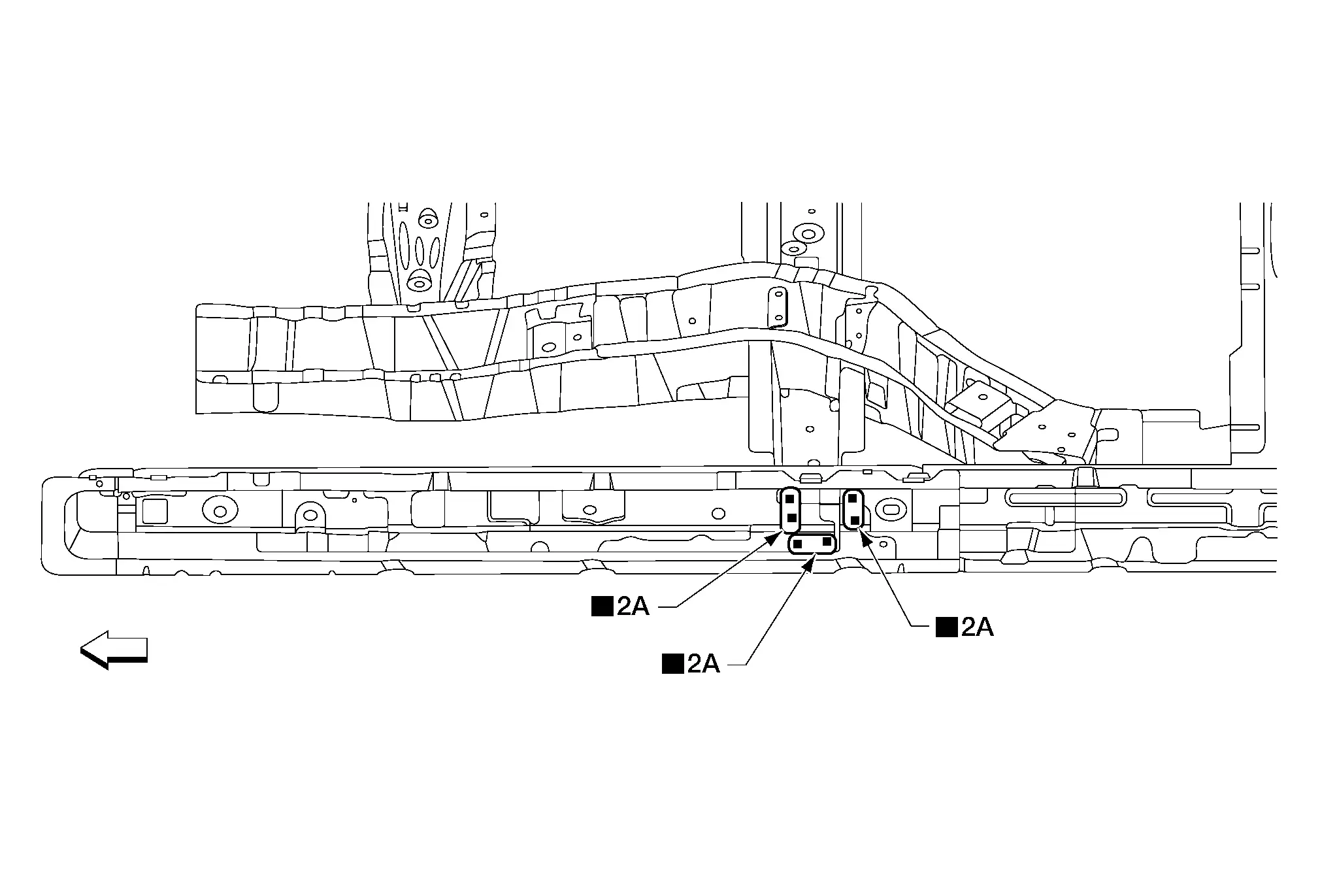
Radiator Core Support Side
Work after front side member connector is removed.
 |
Front | ||||
| Replacement parts | |||||
| • | Radiator core support side | ||||
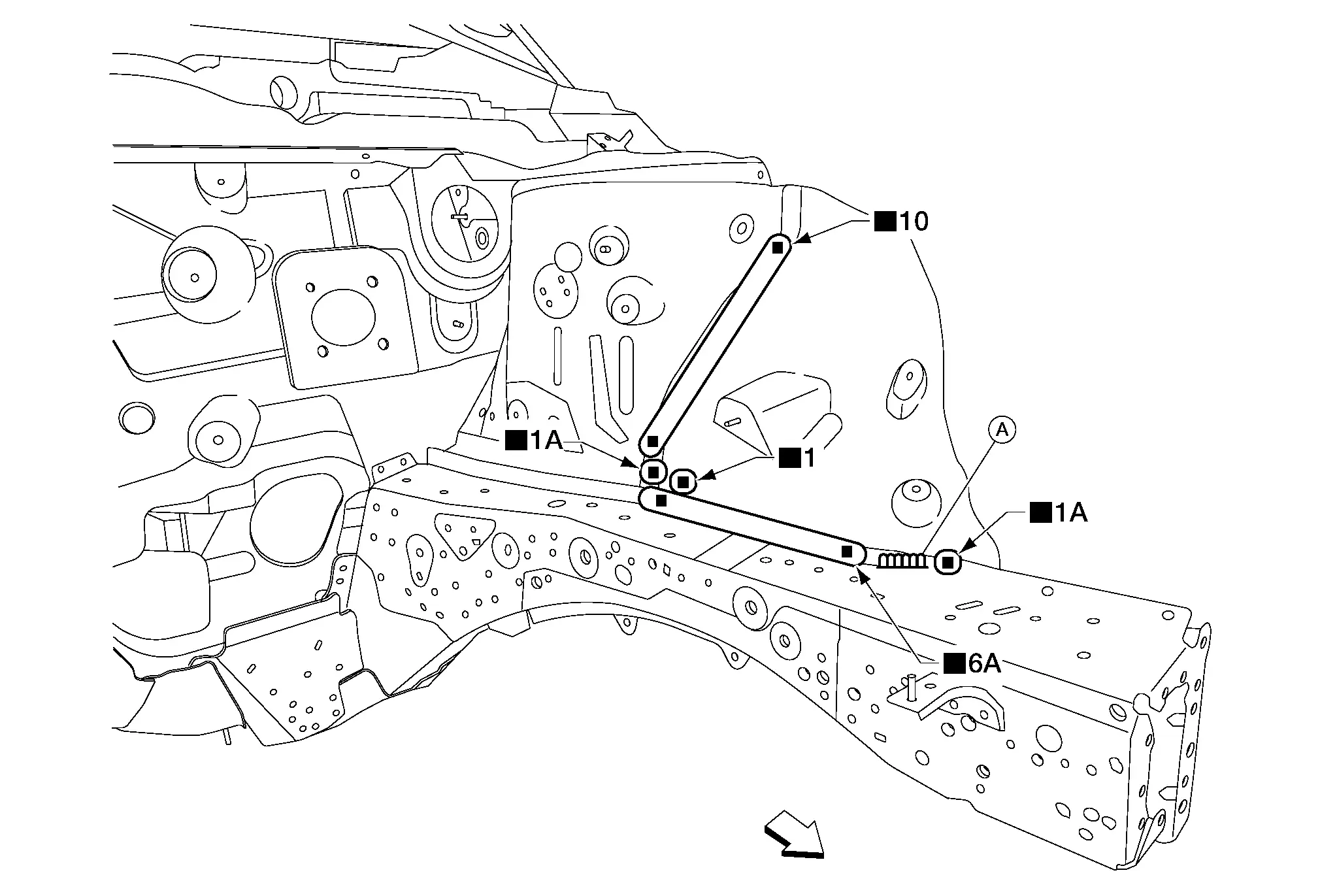
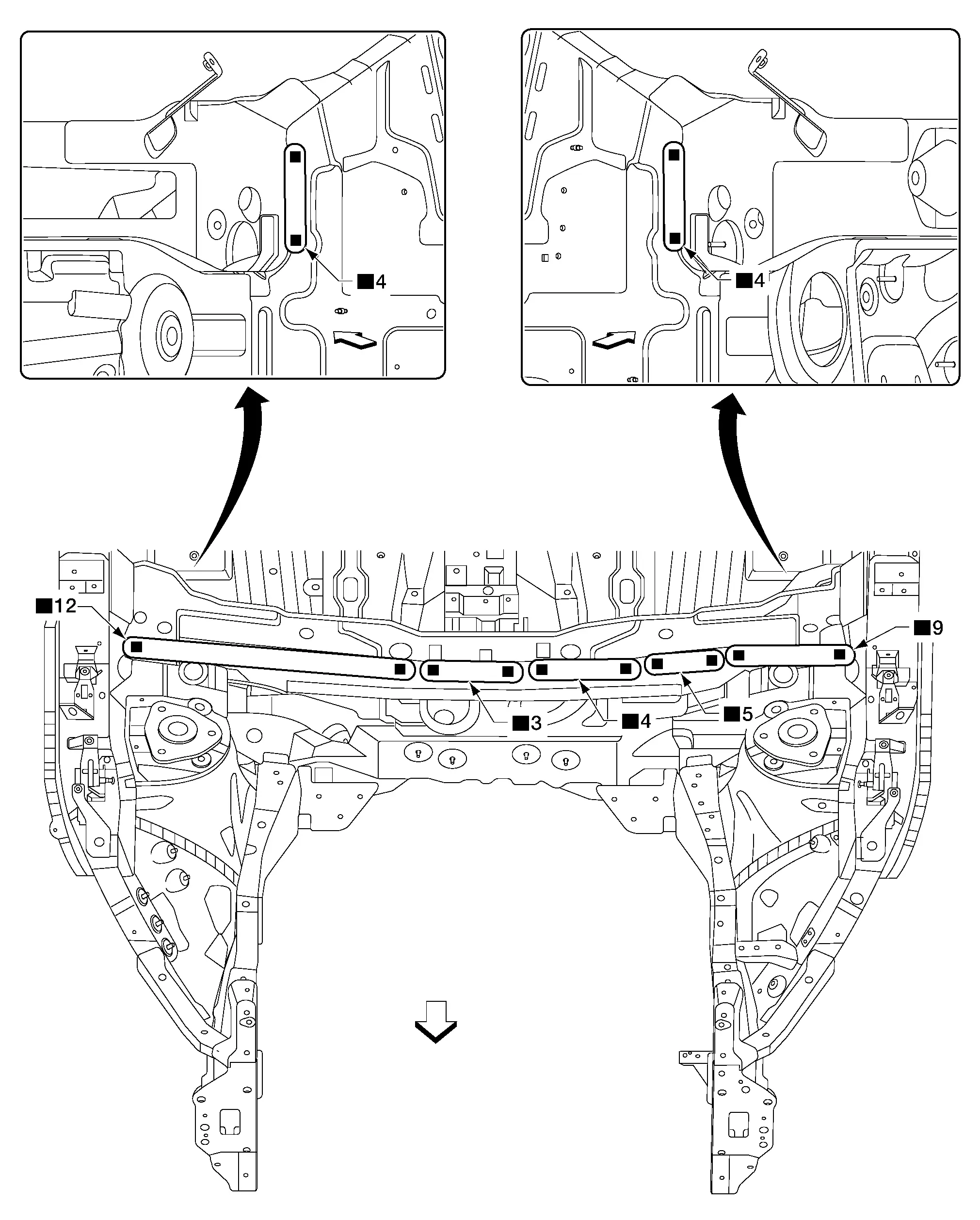
Hoodledge
HOODLEDGE REINFORCEMENT
Work after radiator core support side is removed.
 |
Front | ||||
| Replacement parts | |||||
| • | Hoodledge reinforcement | ||||
HOODLEDGE UPPER
Work after hoodledge reinforcement is removed.
 |
Front | ||||
| Replacement parts | |||||
| • | Hoodledge upper | ||||
BATTERY SUPPORT BRACKET
 |
Front | ||||
| Replacement parts | |||||
| • | Battery support bracket | ||||
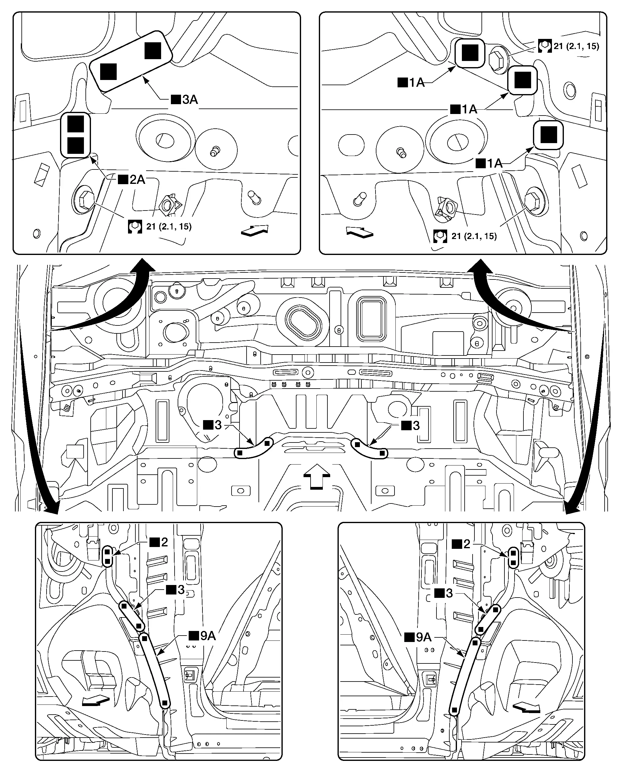
HOODLEDGE LOWER FRONT
Work after hoodledge upper is removed.
| A. | MAG weld | ||||
 |
Front | ||||
| Replacement parts | |||||
| • | Hoodledge lower front | ||||
HOODLEDGE LOWER REAR
Work after hoodledge lower front is removed.
 |
Front | ||||
| Replacement parts | |||||
| • | Hoodledge lower rear | ||||
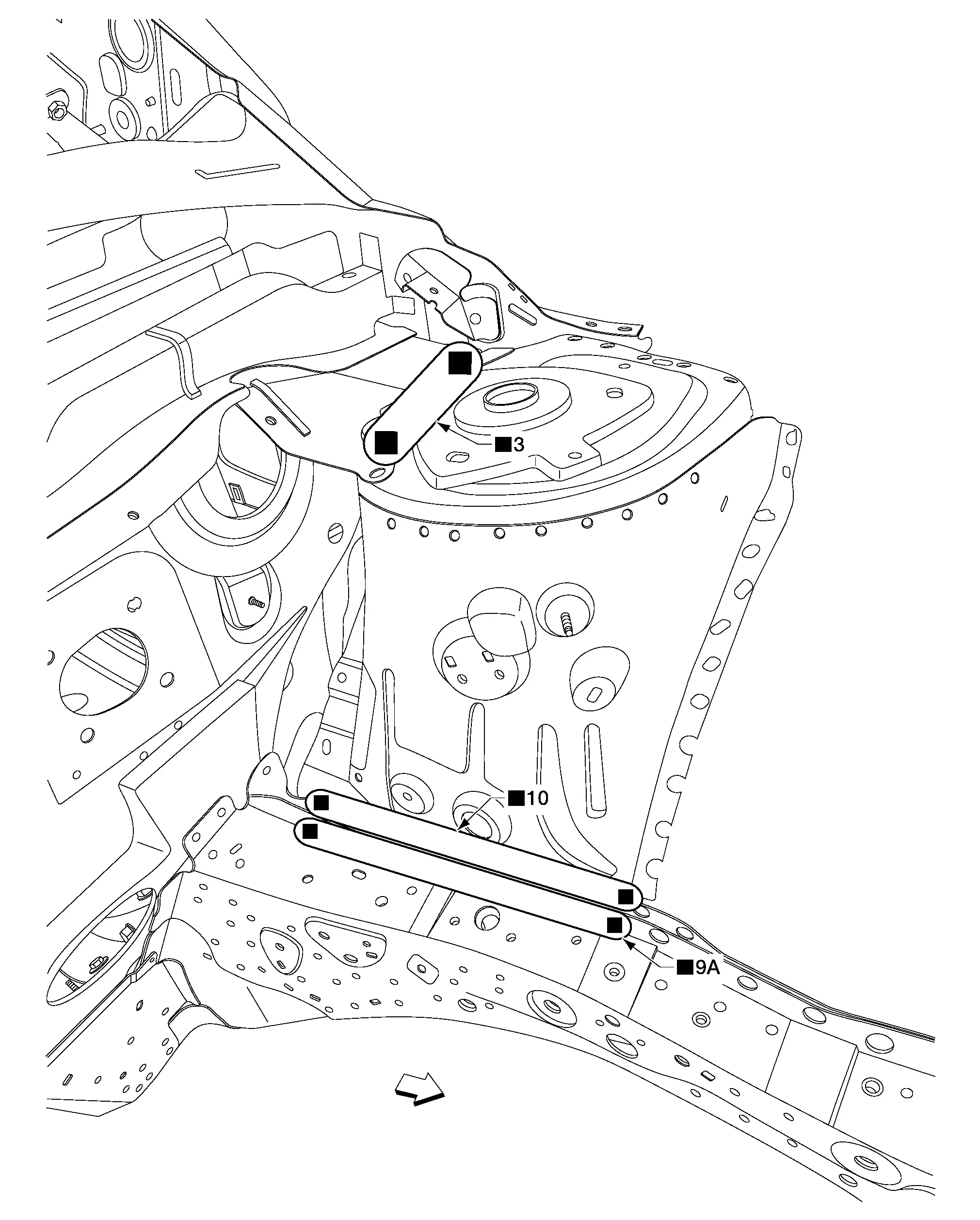
Front Side Member
FRONT SIDE MEMBER CLOSING PLATE
Work after hoodledge lower rear is removed.
| A. | MAG welds | ||||
 |
Front | ||||
| Replacement parts | |||||
| • | Front side member closing plate | ||||
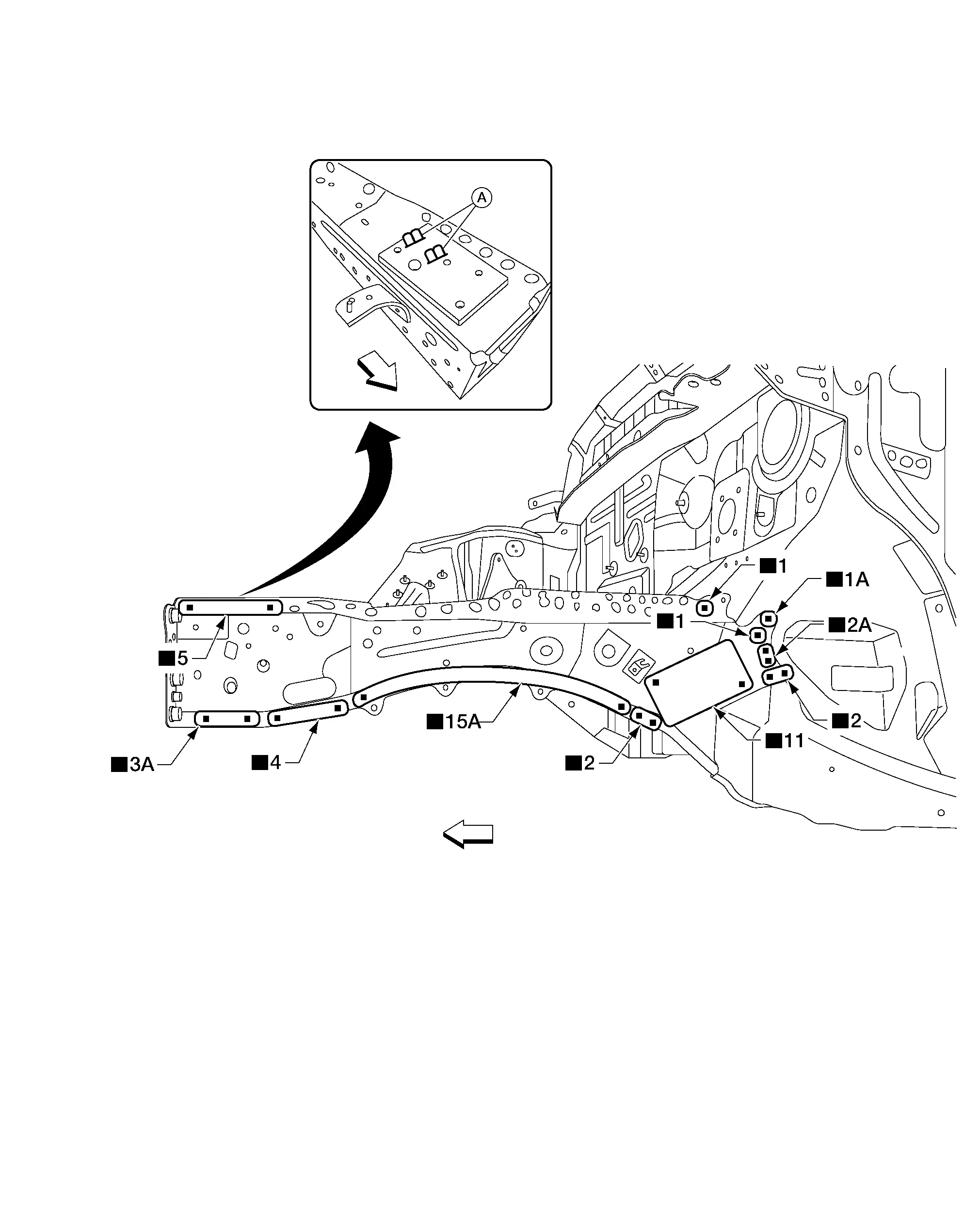
FRONT SIDE MEMBER INNER
Work after front side member closing plate is removed.
 |
Front | ||||
| Replacement parts | |||||
| • | Front side member inner | ||||
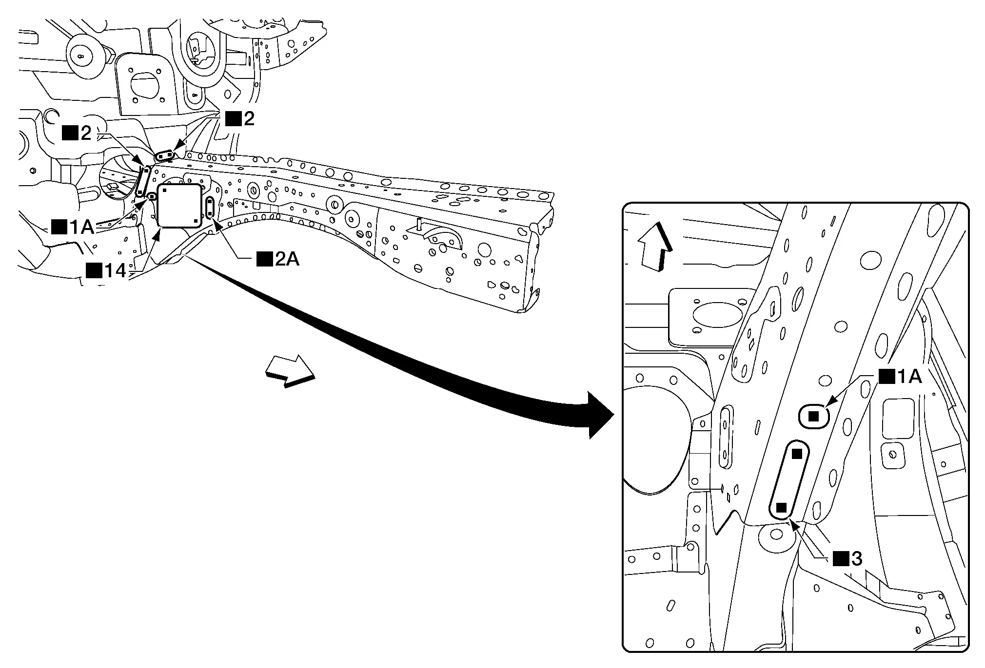
SIDE MEMBER OUTRIGGER
Work after front side member inner is removed.
 |
Front | ||||
| Replacement parts | |||||
| • | Side member outrigger | ||||
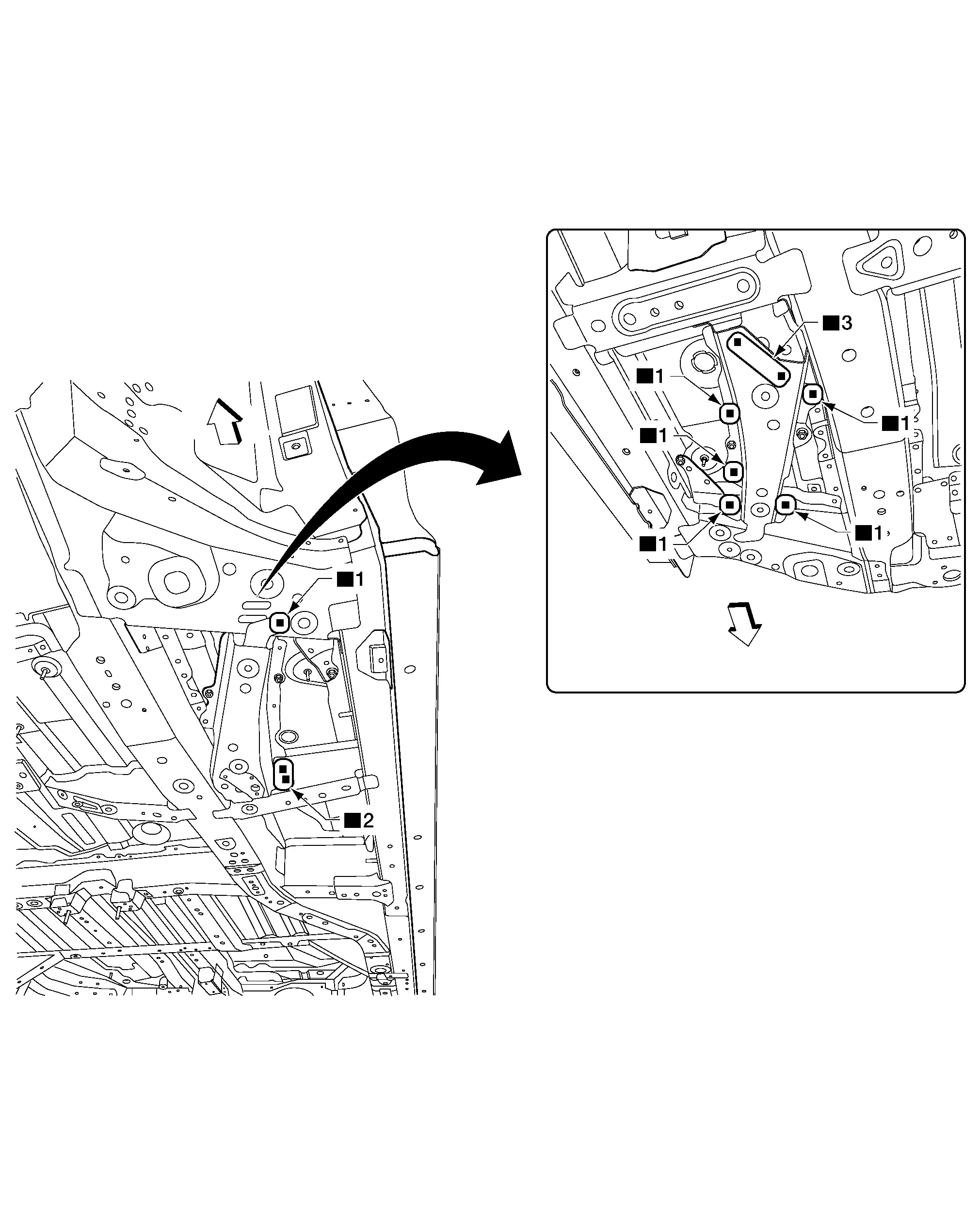
FRONT SIDE MEMBER OUTRIGGER
Work after side member outrigger is removed.
 |
Front | ||||
| Replacement parts | |||||
| • | Front side member outrigger | ||||
Cowl Top
 |
Front | ||||
| Replacement parts | |||||
| • | Cowl top | ||||
Upper Dash
Work after cowl top is removed.
 |
Front | ||||
| Replacement parts | |||||
| • | Upper dash | ||||
Lower Dash
Work after upper dash and front side member stiffeners are removed.
 |
Front | ||||
| Replacement parts | |||||
| • | Lower dash | ||||
Front Floor
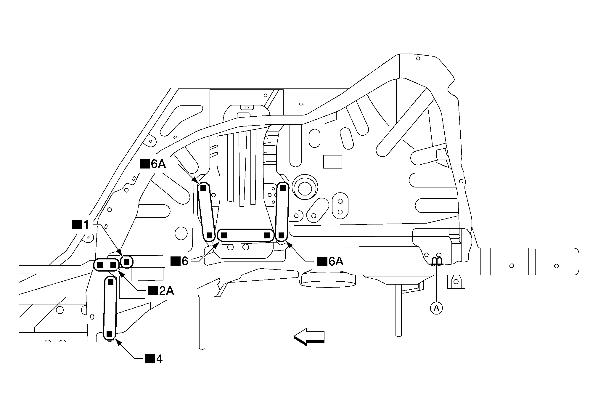
FRONT SIDE MEMBER STIFFENER
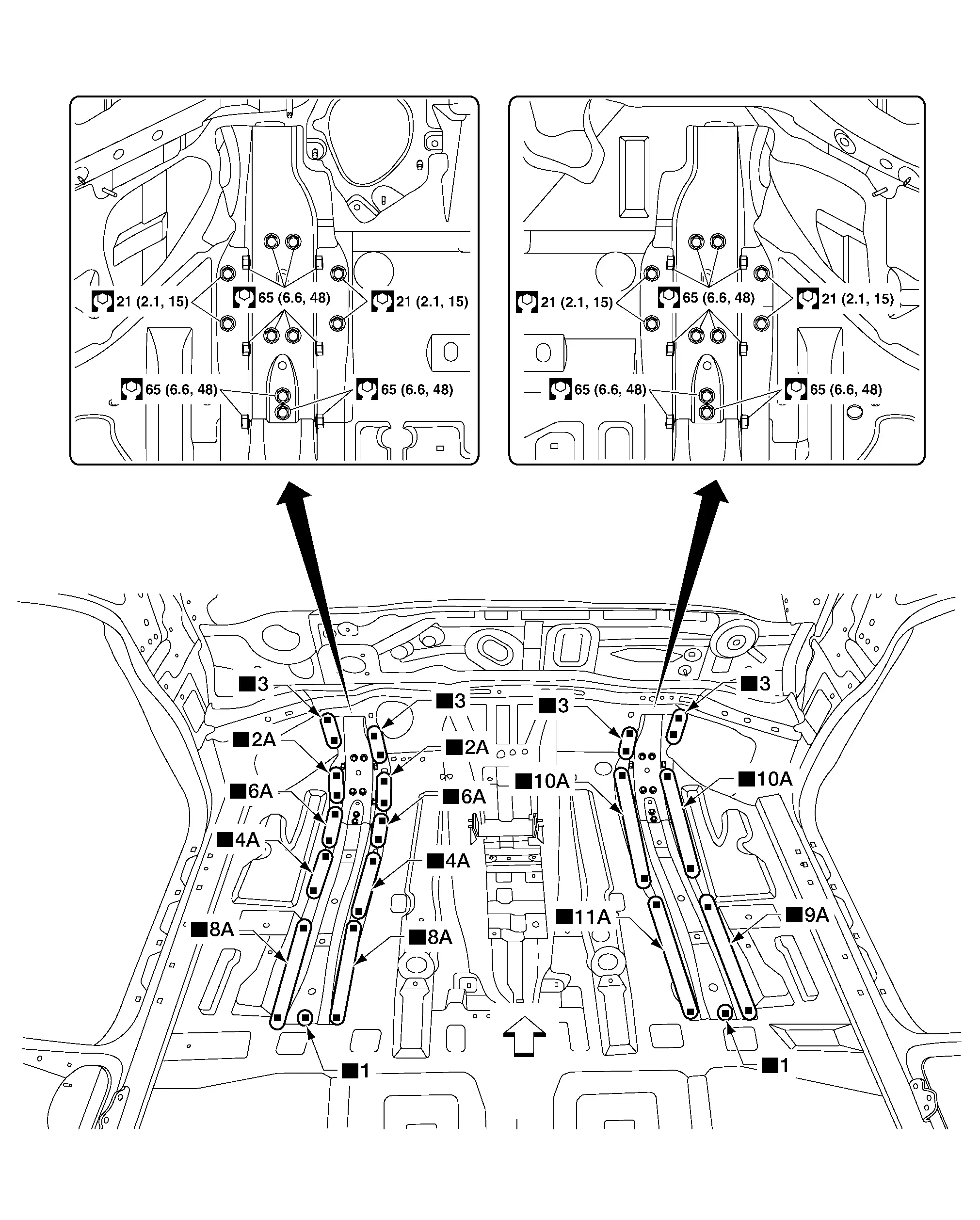
 |
Front | ||||
| Replacement parts | |||||
| • | Front side member stiffener | ||||
INSTRUMENT STAY BRACKET
 |
Front | ||||
| Replacement parts | |||||
| • | Instrument stay bracket | ||||
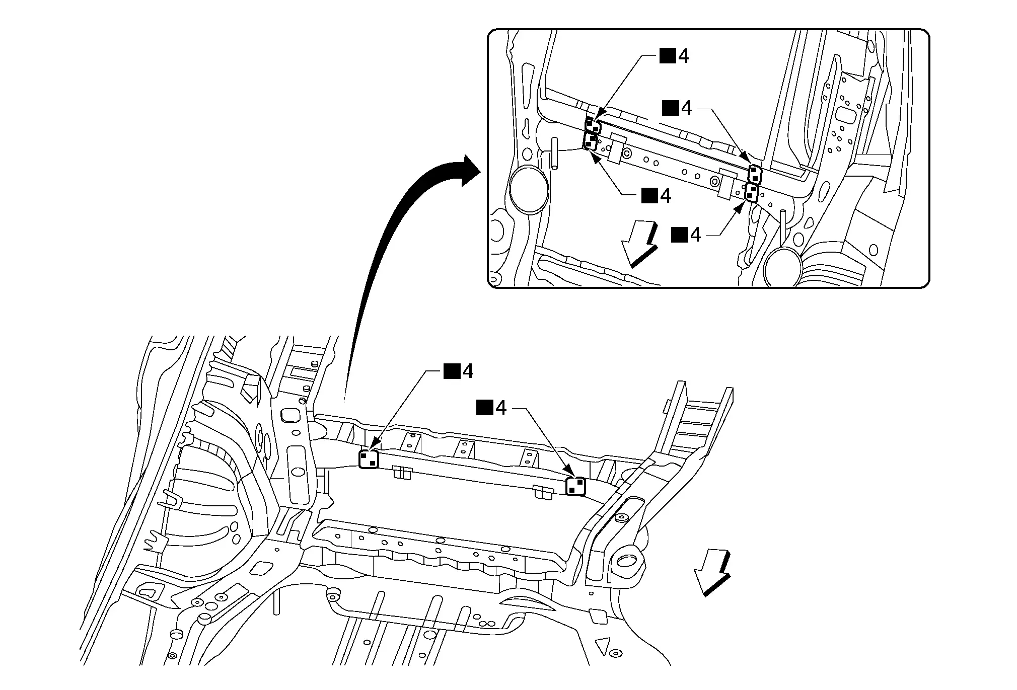
FRONT FLOOR PANEL
Work after lower dash, front side member stiffener and instrument stay bracket are removed.
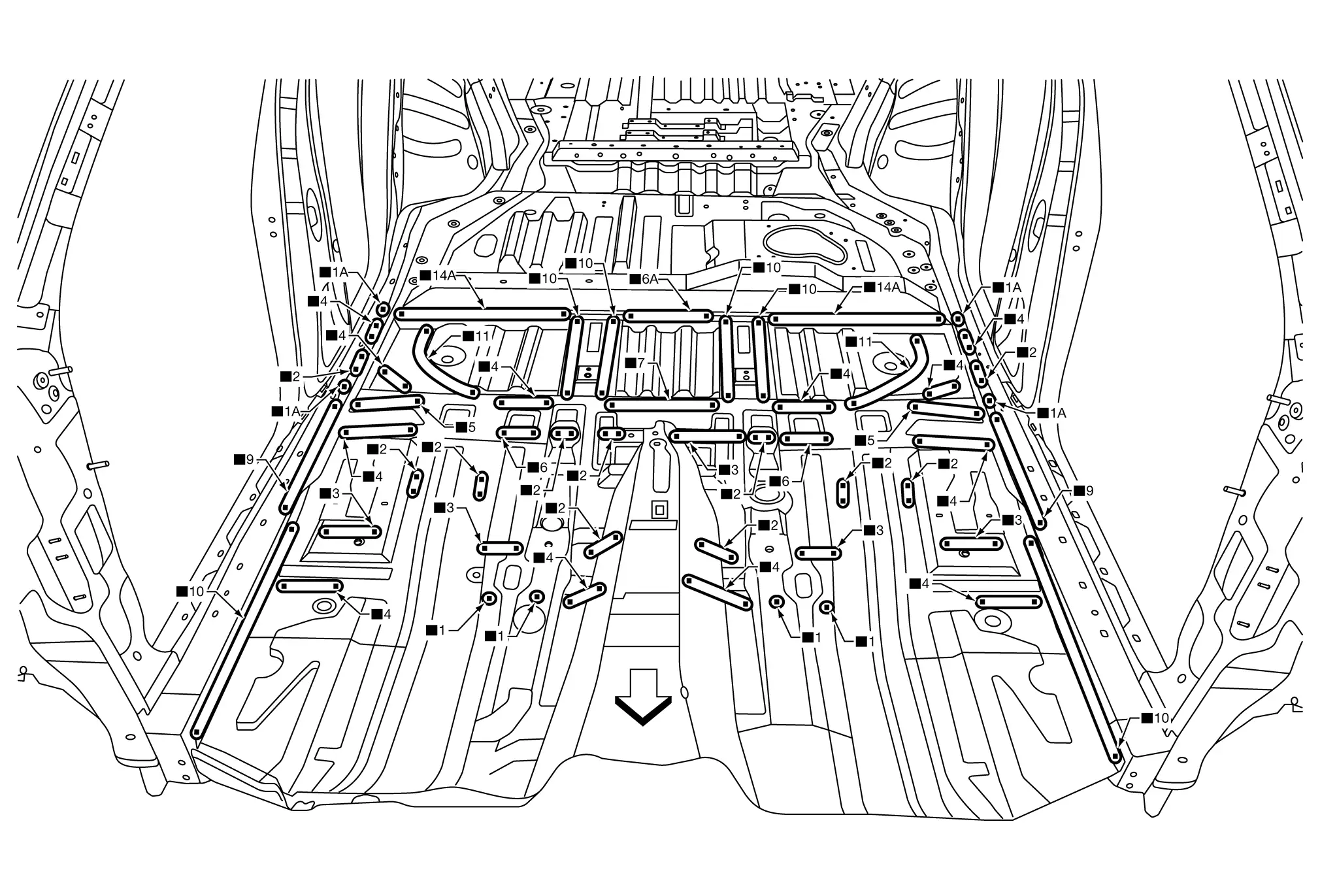
 |
Front | ||||
| Replacement parts | |||||
| • | Front floor panel | ||||
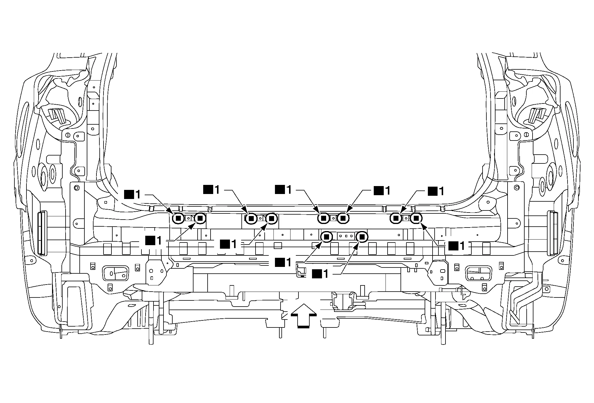
Rear Panel
REAR FENDER BRACES
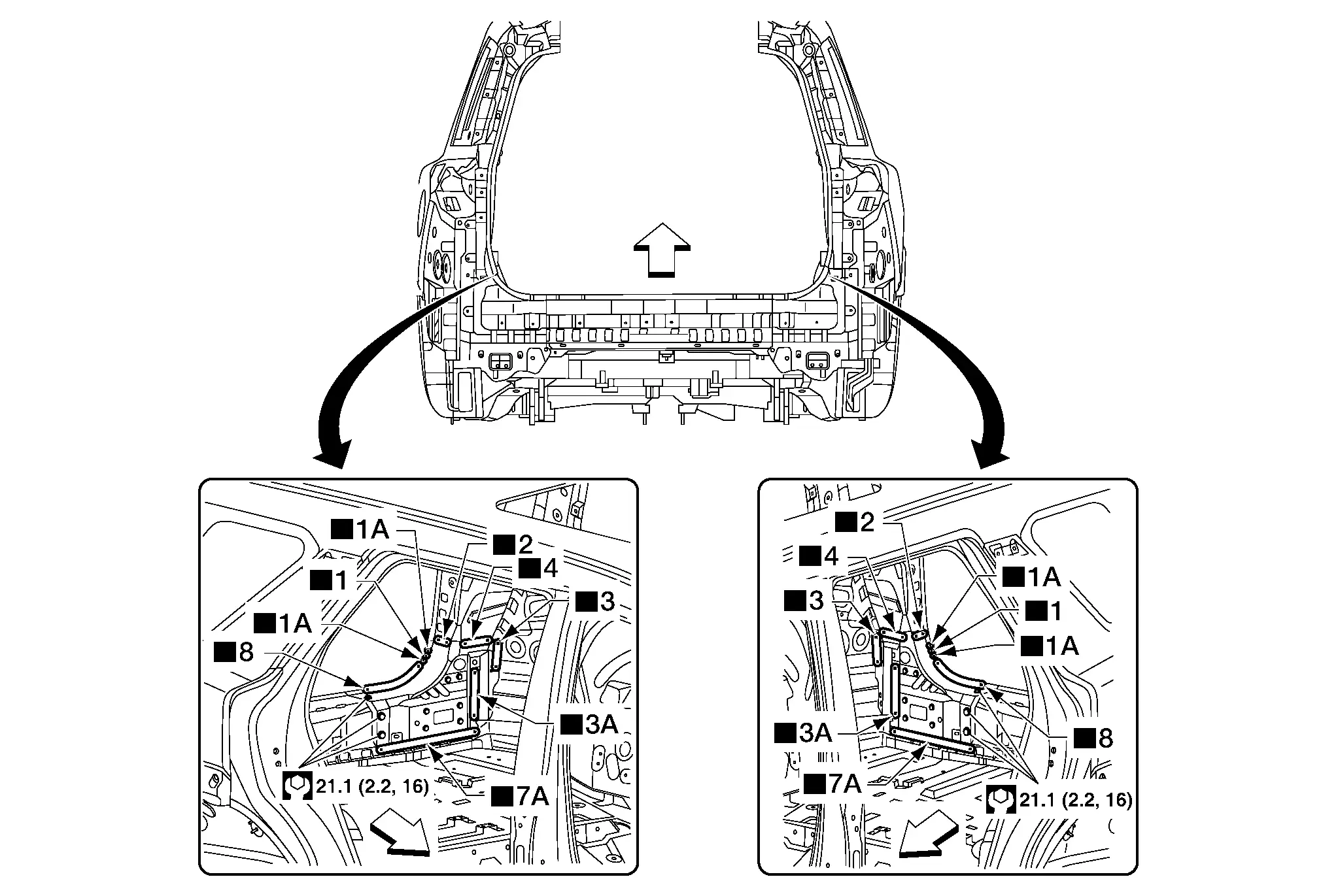
 |
Front | ||||
| Replacement parts | |||||
| • | Rear fender braces | ||||
REAR PANEL BRACKETS
 |
Front | ||||
| Replacement parts | |||||
| • | Rear fascia center brackets | • | Automatic back door warning buzzer bracket | ||
REAR PANEL
Work after rear fender braces are removed.
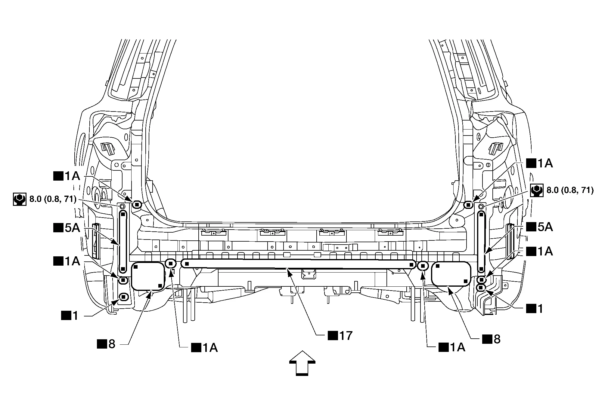
 |
Front | ||||
| Replacement parts | |||||
| • | Rear panel | ||||
Rear Floor
REAR FLOOR BRACKETS AND LOWER SEATBACK SUPPORT
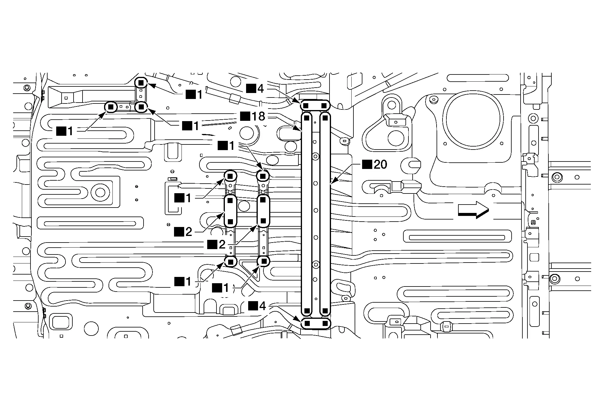
 |
Front | ||||
| Replacement parts | |||||
| • | Woofer bracket (front/rear) | • | Amplifier bracket | • | Lower seatback support |
REAR FLOOR SIDES
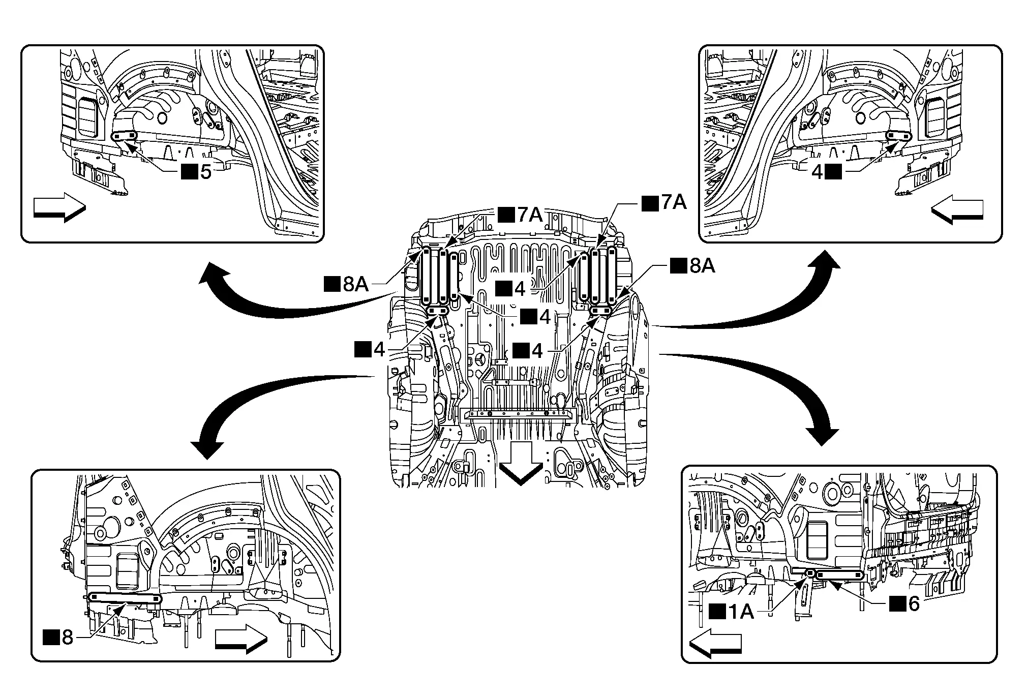
 |
Front | ||||
| Replacement parts | |||||
| • | Rear floor sides | ||||
REAR FLOOR FRONT EXTENSION
Work after front floor is removed.
 |
Front | ||||
| Replacement parts | |||||
| • | Rear floor front extension | ||||
REAR FLOOR FRONT EXTENSION SIDES
Work after rear floor sides and rear floor front extension are removed.
 |
Front | ||||
| Replacement parts | |||||
| • | Rear floor front extension sides | ||||
REAR FLOOR PANEL
Work after rear floor front extension sides are removed.
 |
Front | ||||
| Replacement parts | |||||
| • | Rear floor panel | ||||
Body Side Outer
BODY SIDE OUTER FRONT
Work after hoodledge outer and roof panel are removed.
| A. | Sectioning locations | ||||
 |
Front | ||||
| Replacement parts | |||||
| • | Body side outer front | ||||
 |
For spot welding of steel plate of strength 980 MPa, observe the indicated welding conditions. Refer to Welding of Ultra High Strength Steel. | ||||
BODY SIDE OUTER REAR
Work after roof panel is removed.
| A. | Sectioning locations | ||||
 |
Front | ||||
| Replacement parts | |||||
| • | Body side outer rear | ||||
 |
For spot welding of steel plate of strength 980 MPa, observe the indicated welding conditions. Refer to Welding of Ultra High Strength Steel. | ||||
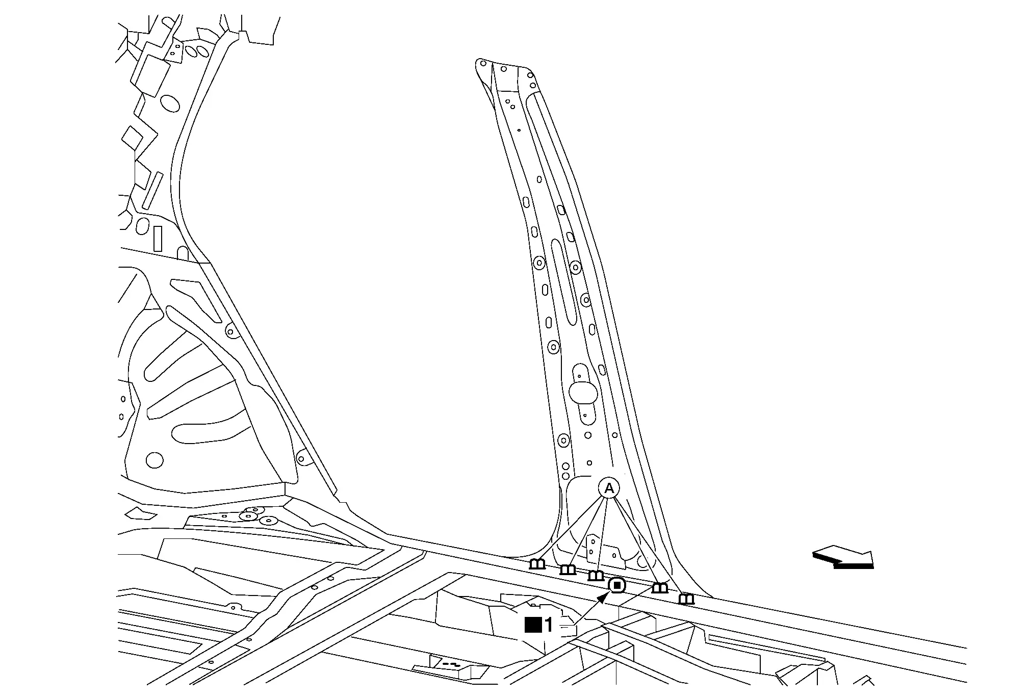
Front Pillar Outer (Partial)
Work after hoodledge outer is removed.
| A. | Sectioning location | ||||
 |
Front | ||||
| Replacement parts | |||||
| • | Front pillar outer (partial) | ||||
 |
For spot welding of steel plate of strength 980 MPa, observe the indicated welding conditions. Refer to Welding of Ultra High Strength Steel. | ||
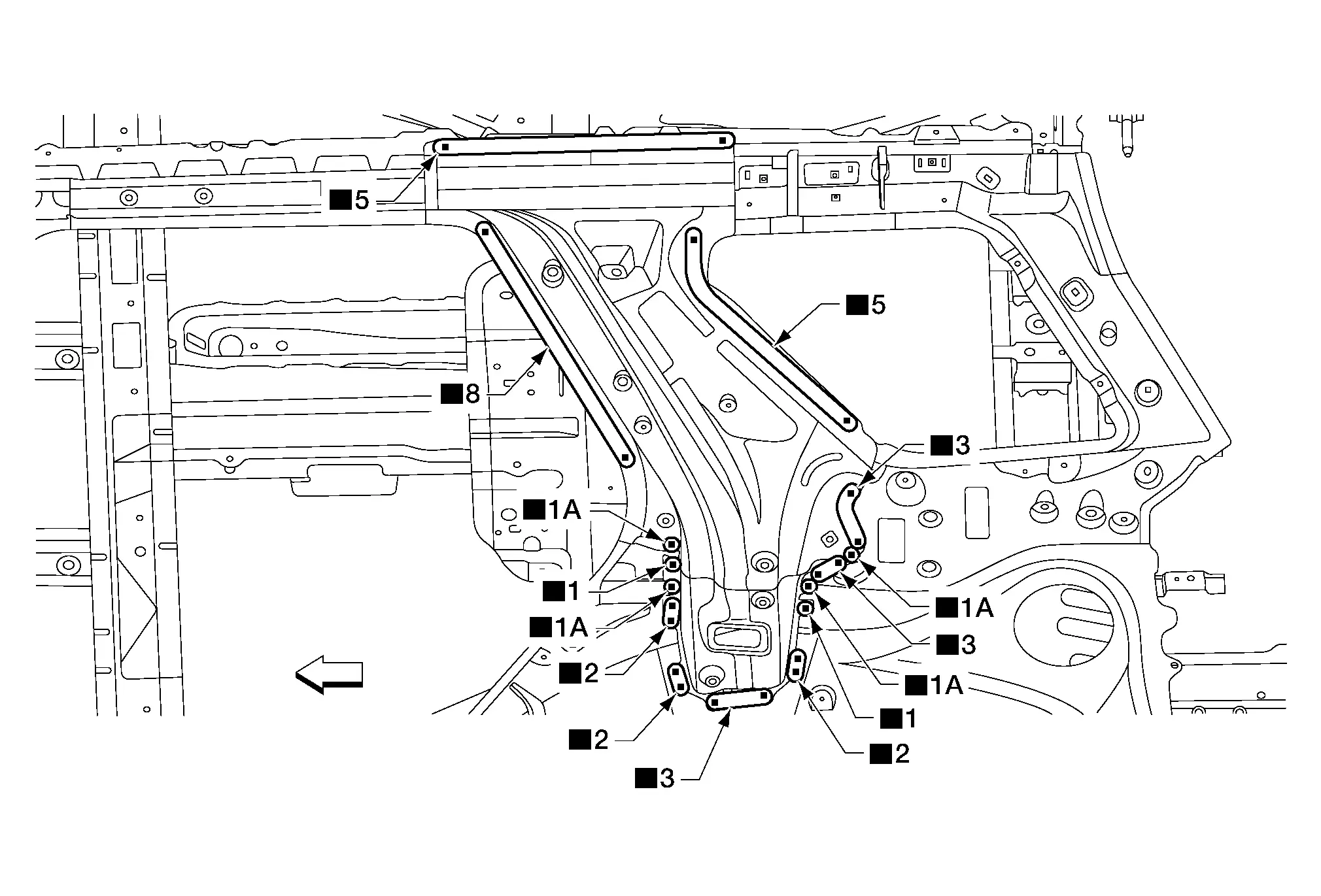
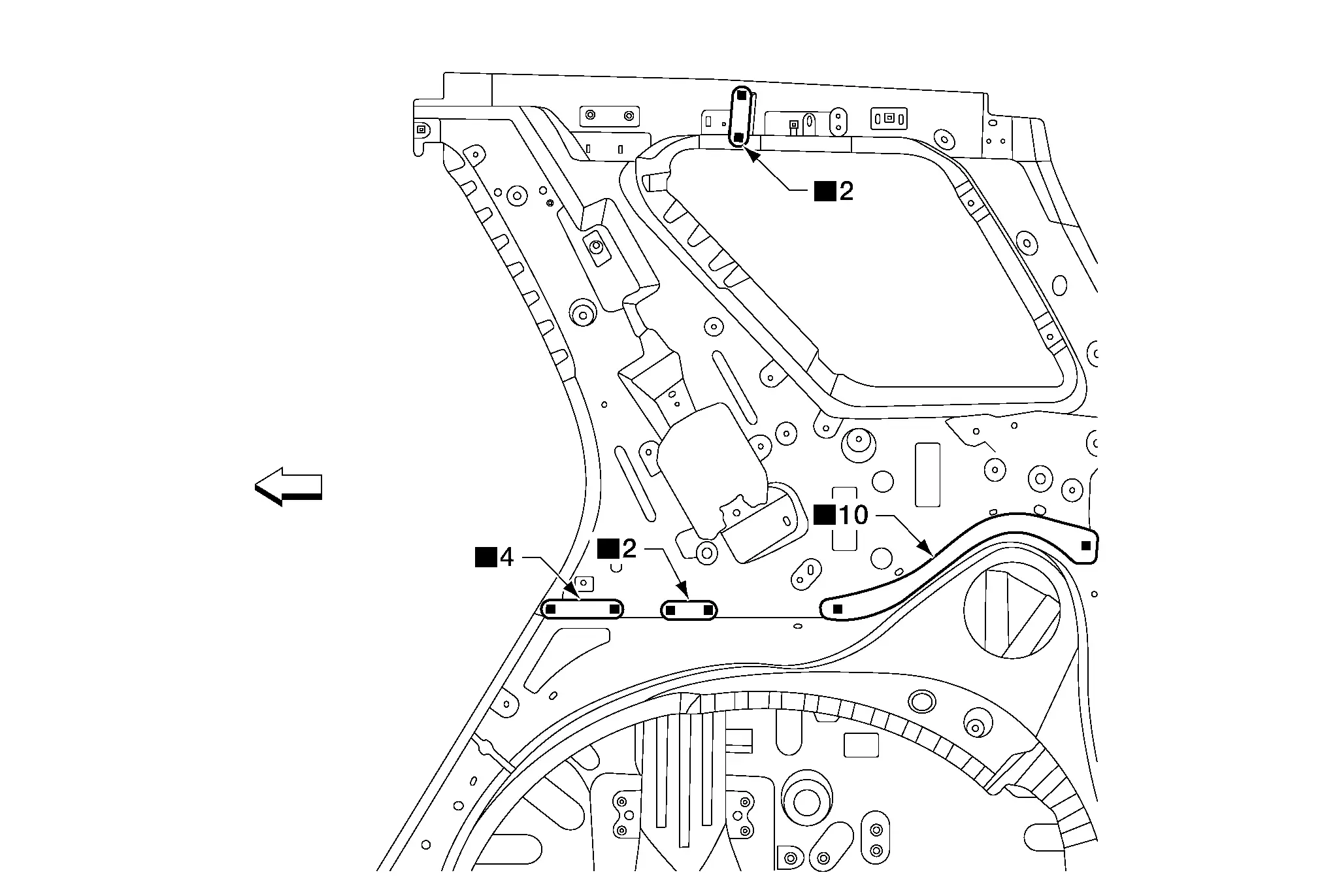
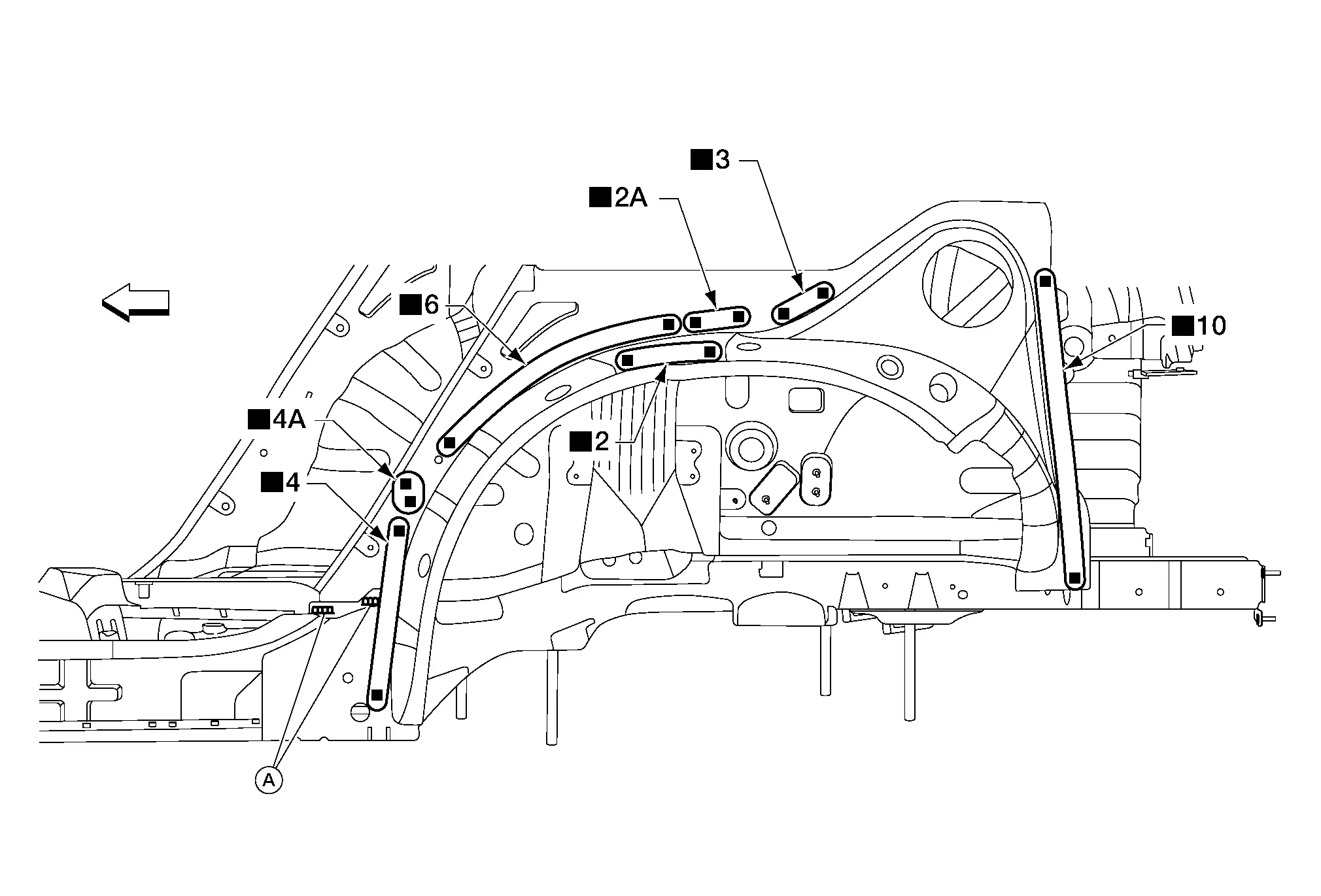
Front Pillar Upper Hinge Brace
Work after front pillar outer (partial) is removed.
 |
Front | ||||
| Replacement parts | |||||
| • | Front pillar upper hinge brace | ||||
Center Pillar Outer (Partial)
Unit: mm (in)
| A. | Sectioning location | B. | 180.0 (7.09) | C. | 140.0 (5.51) | D. | 110.0 (4.33) |
 |
Front | ||||||
| Replacement parts | |||||||
| • | Center pillar outer (partial) | ||||||
Center Pillar Reinforcement
Work after center pillar outer (partial) is removed.
 |
Front | ||||
| Replacement parts | |||||
| • | Center pillar reinforcement | ||||
Sill Outer (Partial)
| A. | Sectioning location | ||||
 |
Front | ||||
| Replacement parts | |||||
| • | Sill outer (partial) | ||||
 |
For spot welding of steel plate of strength 980 MPa, observe the indicated welding conditions. Refer to Welding of Ultra High Strength Steel. | ||
Sill Outer Reinforcement
Work after sill outer (partial) is removed.
| A. | MAG welds | ||||
 |
Front | ||||
| Replacement parts | |||||
| • | Sill outer reinforcement | ||||
 |
For spot welding of steel plate of strength 980 MPa, observe the indicated welding conditions. Refer to Welding of Ultra High Strength Steel. | ||
Rear Fender (Partial)
| A. | Sectioning location | ||||
 |
Front | ||||
| Replacement parts | |||||
| • | Rear fender (partial) | ||||
 |
For spot welding of steel plate of strength 980 MPa, observe the indicated welding conditions. Refer to Welding of Ultra High Strength Steel. | ||
Rear Fender Extension (Partial)
Work after rear panel is removed.
| A. | Sectioning location | ||||
 |
Front | ||||
| Replacement parts | |||||
| • | Rear fender extension (partial) | ||||
Rear Combination Lamp Base
Work after body side outer rear is removed.
 |
Front | ||||
| Replacement parts | |||||
| • | Rear combination lamp base | • | Rear fascia bracket | ||
Back Pillar Outer
Work after rear combination lamp base is removed.
 |
Front | ||||
| Replacement parts | |||||
| • | Back pillar outer | ||||
Sill Outer Reinforcement Rear
Work after sill outer reinforcement is removed.
 |
Front | ||||
| Replacement parts | |||||
| • | Sill outer reinforcement rear | ||||
Back Pillar Inner
Work after back pillar outer is removed.
 |
Front | ||||
| Replacement parts | |||||
| • | Back pillar inner | ||||
Roof Side Rail
ROOF SIDE RAIL OUTER REINFORCEMENT
Work after center pillar reinforcement is removed.
 |
Front | ||||
| Replacement parts | |||||
| • | Roof side rail outer reinforcement | ||||
ROOF SIDE RAIL INNER
Work after roof side rail outer reinforcement is removed.
| A. | MAG welds | ||||
 |
Front | ||||
| Replacement parts | |||||
| • | Roof side rail inner | ||||
Dash Side Inner
Work after roof side rail inner is removed.
 |
Front | ||||
| Replacement parts | |||||
| • | Dash side inner | ||||
Center Pillar Inner Reinforcement
Work after roof side rail inner is removed.
| A. | MAG welds | ||||
 |
Front | ||||
| Replacement parts | |||||
| • | Center pillar inner reinforcement | ||||
Rear Pillar Inner
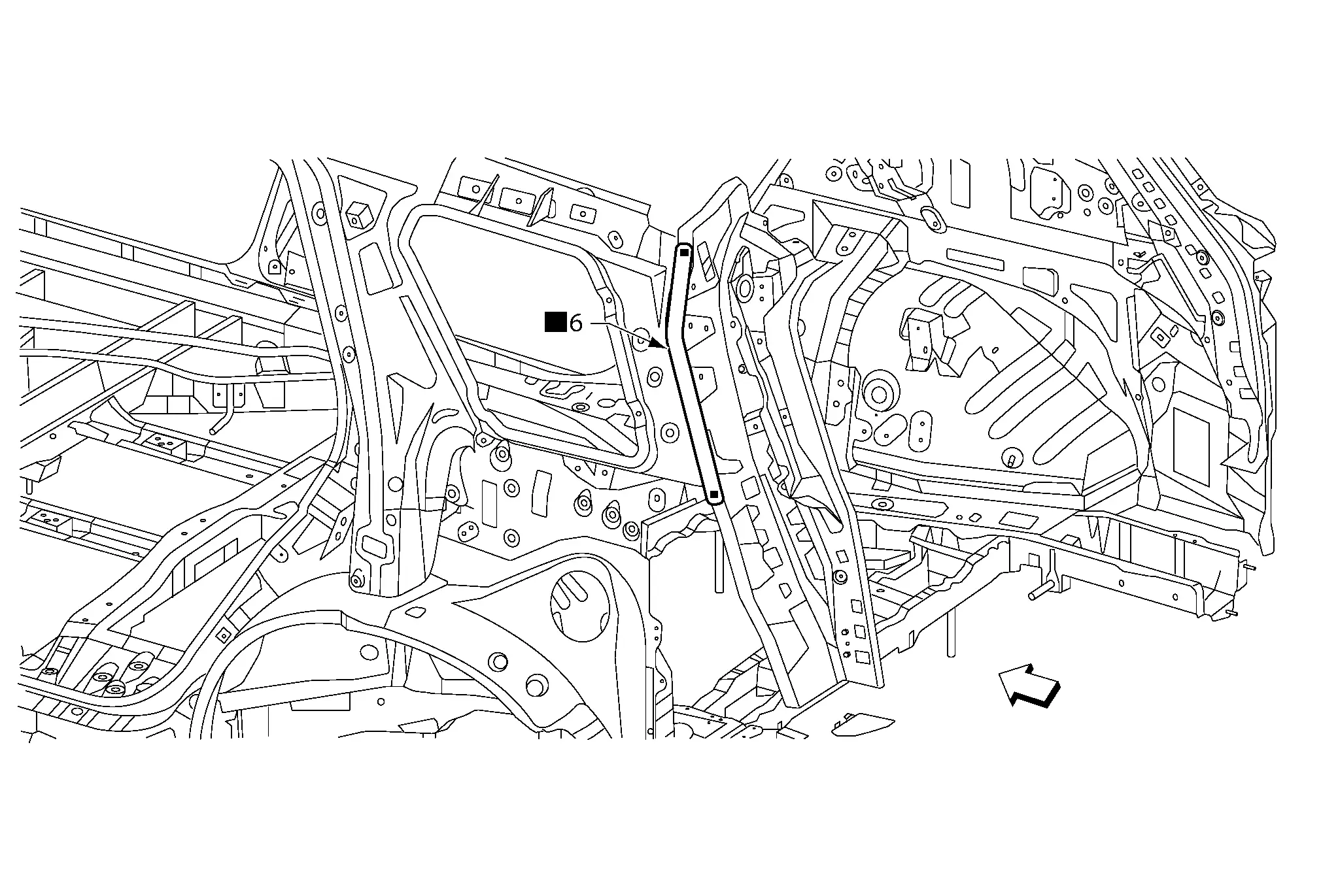
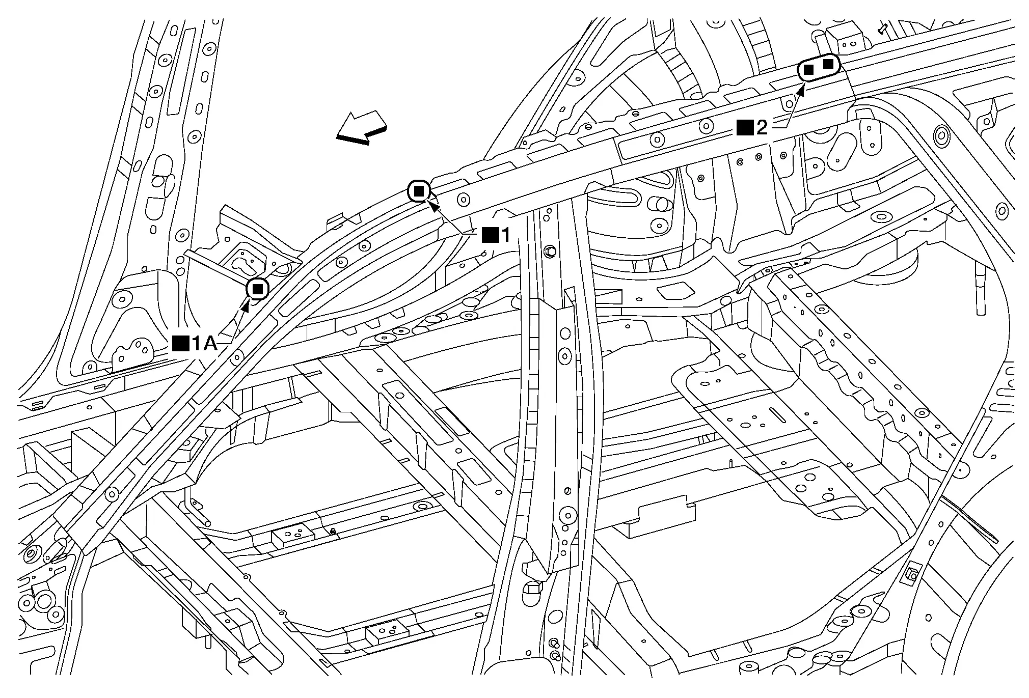
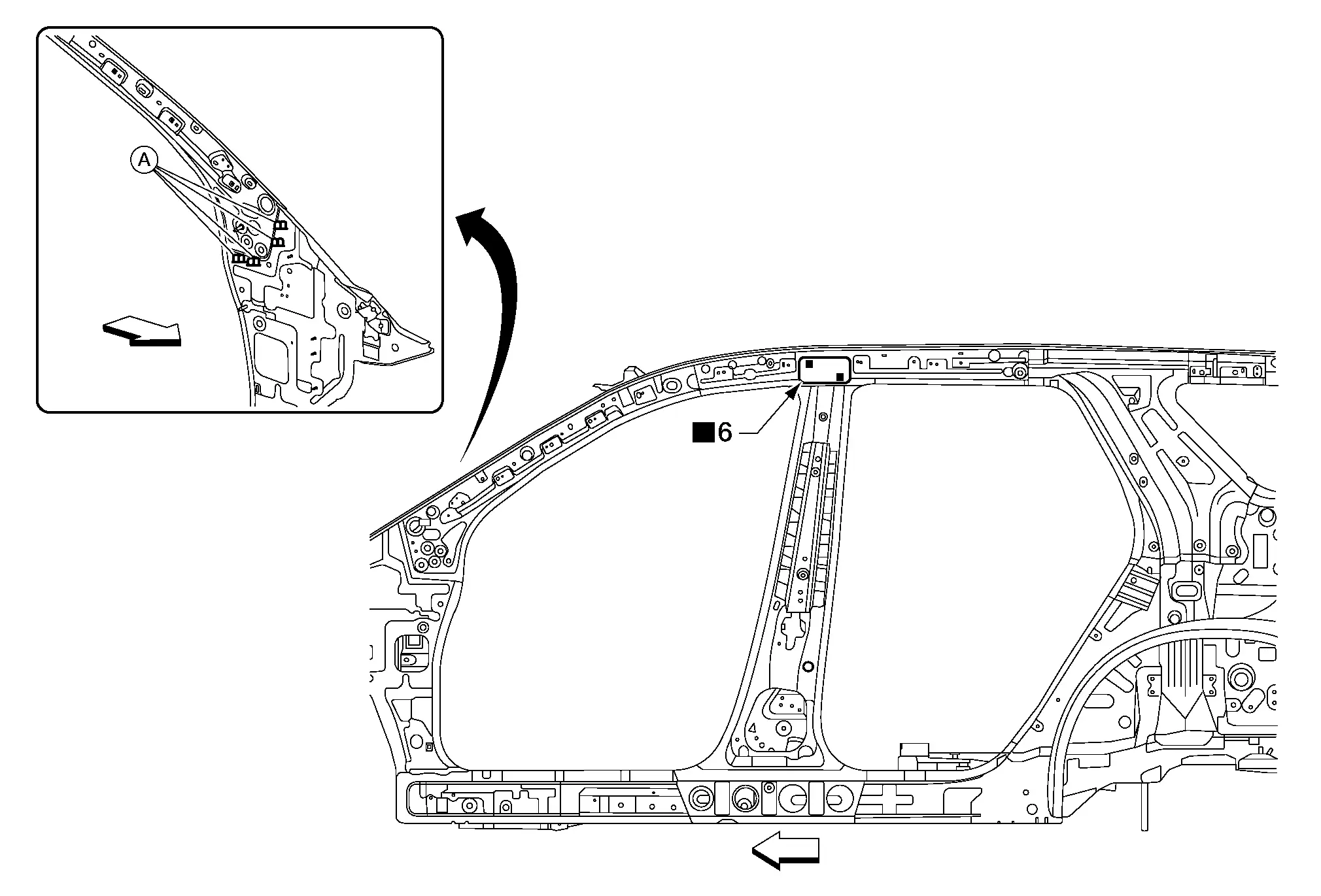
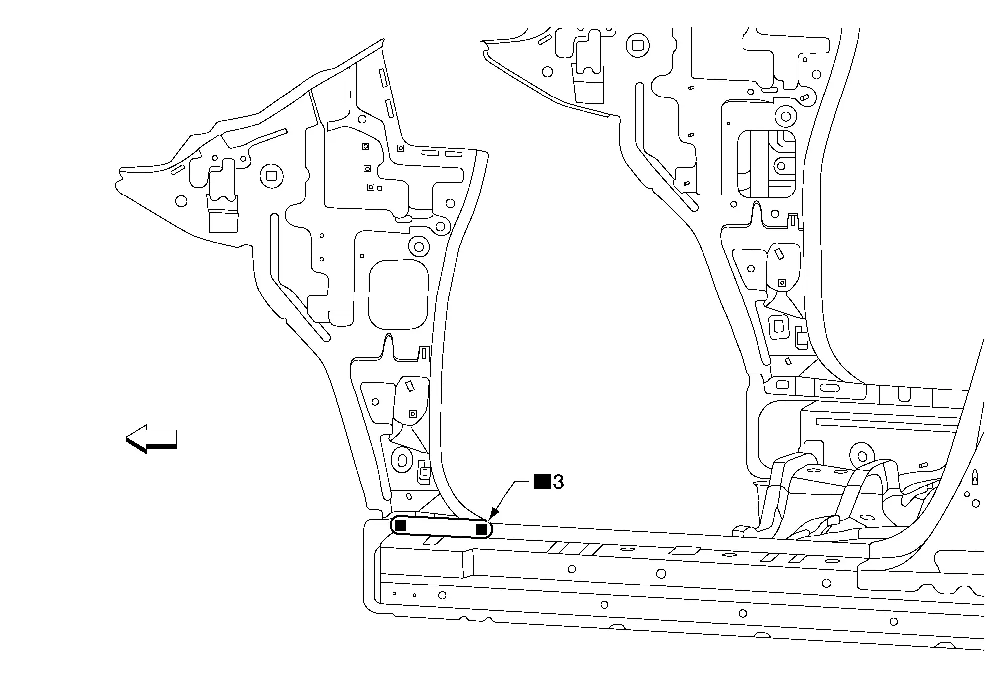
REAR PILLAR INNER REINFORCEMENT
Work after roof side rail outer is removed.
 |
Front | ||||
| Replacement parts | |||||
| • | Rear pillar inner reinforcement | ||||
REAR PILLAR INNER
Work after rear pillar inner reinforcement is removed.
 |
Front | ||||
| Replacement parts | |||||
| • | Rear pillar inner | ||||
Rear Wheelhouse
REAR WHEELHOUSE OUTER
Work after sill outer reinforcement rear and rear pillar inner are removed.
| A. | MAG welds | ||||
 |
Front | ||||
| Replacement parts | |||||
| • | Rear wheelhouse outer | ||||
REAR WHEELHOUSE INNER
Work after rear wheelhouse outer is removed.
| A. | MAG weld | ||||
 |
Front | ||||
| Replacement parts | |||||
| • | Rear wheelhouse inner | ||||
7th Crossmember
Work after rear floor panel is removed.
 |
Front | ||||
| Replacement parts | |||||
| • | 7th crossmember | ||||
5th Crossmember
Work after rear floor panel is removed.
 |
Front | ||||
| Replacement parts | |||||
| • | 5th crossmember | ||||
Rear Side Member
Work after 7th crossmember and 5th crossmember are removed.
 |
Front | ||||
| Replacement parts | |||||
| • | Rear side member | ||||
Rear Seat Belt Anchor Inner Reinforcement
Work after rear side member is removed.
 |
Front | ||||
| Replacement parts | |||||
| • | Rear seat belt anchor inner reinforcement | ||||
2nd Crossmember
Work after front floor panel is removed.
 |
Front | ||||
| Replacement parts | |||||
| • | 2nd crossmember | ||||
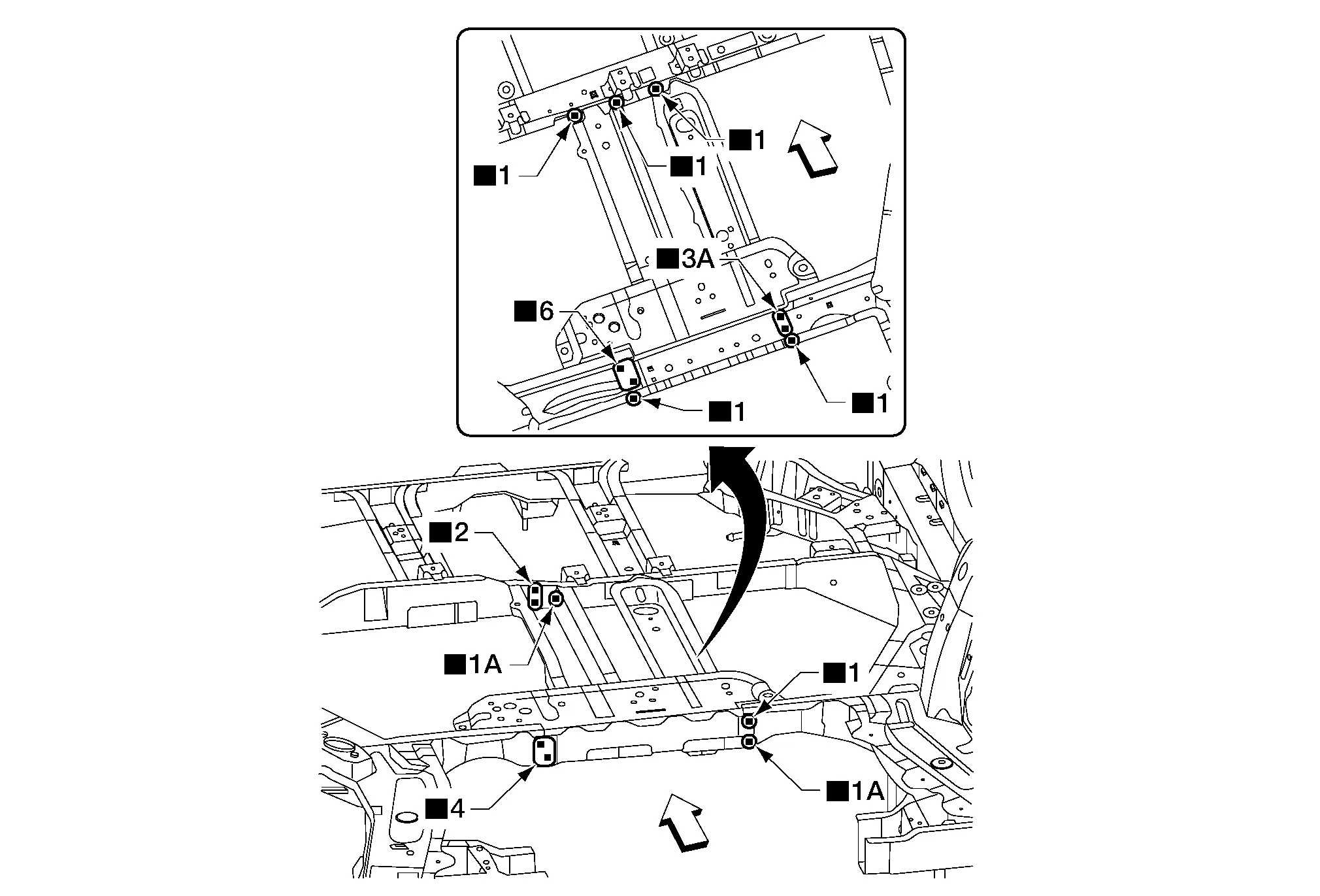
Front Side Member Center Extension
Work after 2nd crossmember is removed.
 |
Front | ||||
| Replacement parts | |||||
| • | Front side member center extension | ||||
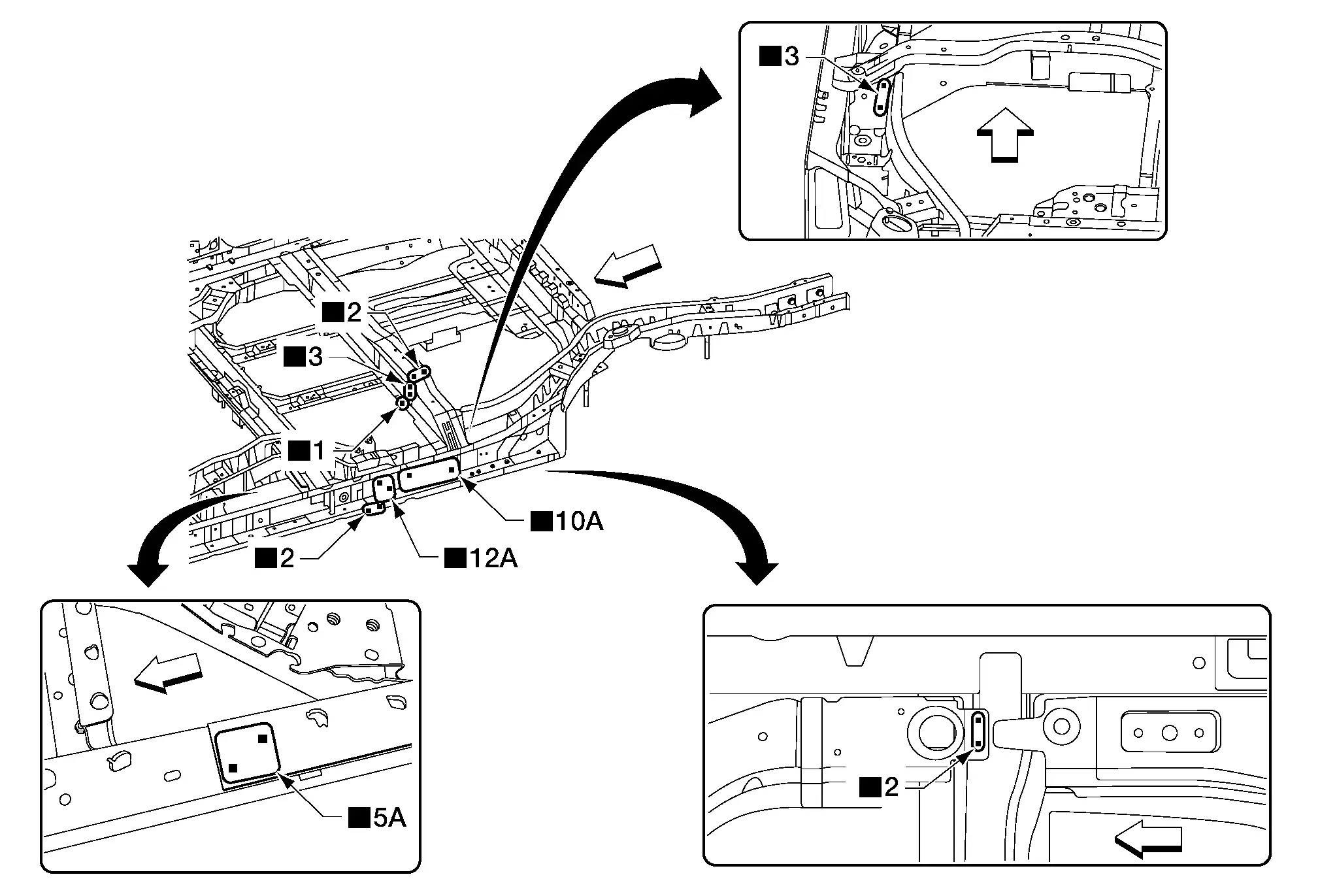
Sill Inner Reinforcement
Work after front side member center extension is removed.
 |
Front | ||||
| Replacement parts | |||||
| • | Sill inner reinforcement | ||||
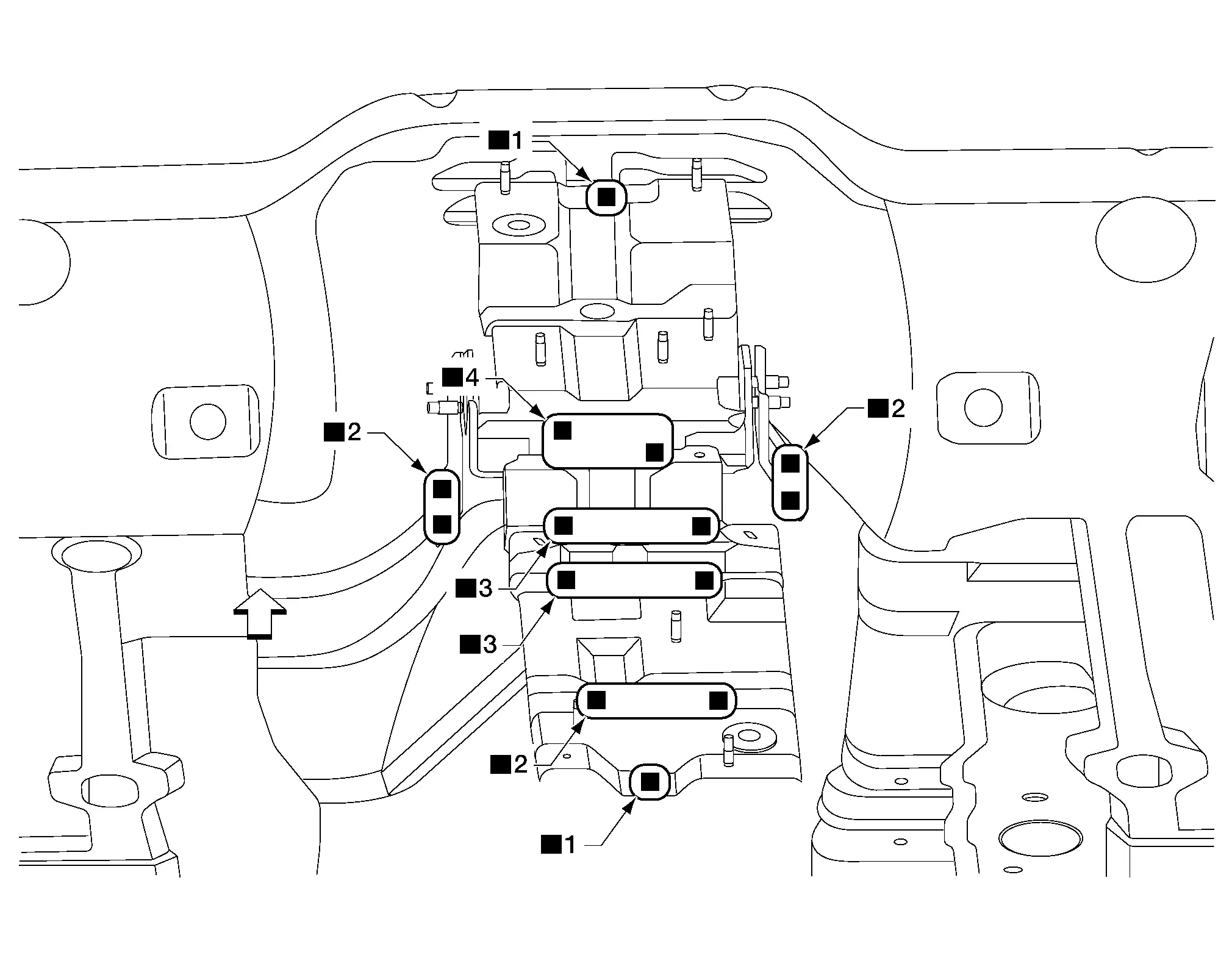
3rd Crossmember
Work after sill inner reinforcement is removed.
 |
Front | ||||
| Replacement parts | |||||
| • | 3rd crossmember | ||||
Back Door Outer
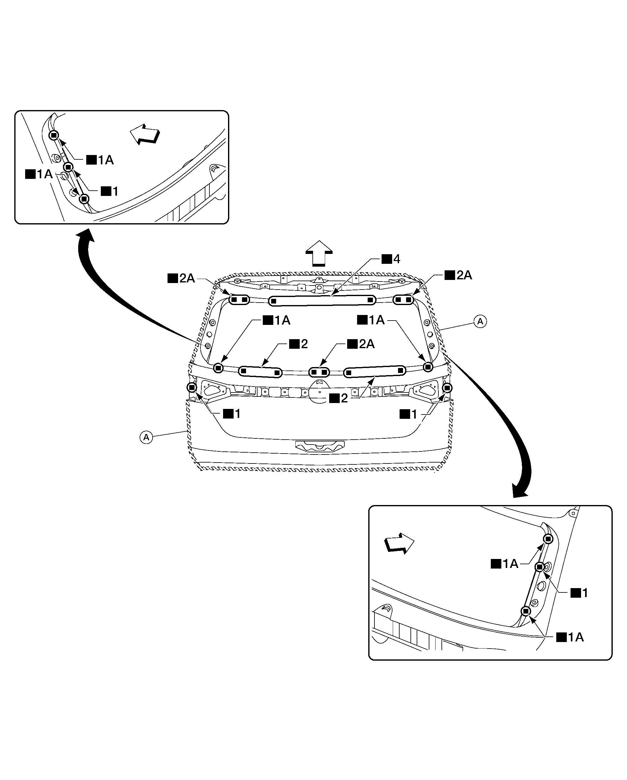
| A. | Adhesive | ||||
 |
Front | ||||
| Replacement parts | |||||
| • | Back door outer | ||||
 NOTE:
NOTE:
-
Always follow proper procedure for door hemming. Refer to Door Hemming.
-
Use commercially available panel bonding adhesive for door hemming:
<Adhesive> 3M™ 08115 Panel Bonding Adhesive or equivalent

Nissan Pathfinder (R53) 2022-2026 Service Manual
Removal and Installation
Contact Us
Nissan Pathfinder Info Center
Email: info@nipathfinder.com
Phone: +1 (800) 123-4567
Address: 123 Pathfinder Blvd, Nashville, TN 37214, USA
Working Hours: Mon–Fri, 9:00 AM – 5:00 PM (EST)
