Nissan Pathfinder: Body Repair - Precaution
Precautions Nissan Pathfinder 2022
Precautions for Body Repair
WARNING:
-
The repair information in this section is intended for trained body repair technicians who have attained a high level of skill and experience (e.g. ASE Collision Repair Certification, I-CAR Professional Development Program [PDP] training, etc.) in repairing collision damaged Nissan Pathfinder vehicles using appropriate tools and equipment. Performing repairs without the proper training, tools or equipment could damage the Nissan Pathfinder vehicle or cause personal injury or death to you or others.
-
The information in this Body Repair Manual is a guideline for repairing collision damaged Nissan Pathfinder vehicles. However, this information cannot cover all possible ways that a vehicle can be damaged. As such, the body repair technician is responsible for making sure that the repair does not affect the structural integrity or safety of the Nissan Pathfinder vehicle. Improper repair of a damaged vehicle may result in a collision, property damage, personal injury or death.
-
Nissan recommends using only new genuine Nissan replacement body parts. Use of used, salvaged or aftermarket body parts is not recommended by Nissan. Non-genuine Nissan components may affect the Nissan Pathfinder vehicle's structural integrity and crash safety performance, which could result in serious personal injury or death in an accident.
Precaution for Supplemental Restraint System (SRS) "AIR BAG" and "SEAT BELT PRE-TENSIONER"
The Supplemental Restraint System such as “AIR BAG” and “SEAT BELT PRE-TENSIONER”, used along with a front seat belt, helps to reduce the risk or severity of injury to the driver and front passenger for certain types of collisions.
Information necessary to service the system safely is included in the “SRS AIR BAG” and “SEAT BELT” sections of this Service Manual.
WARNING:
Always observe the following items for preventing accidental activation:
-
To avoid rendering the SRS inoperative, which could increase the risk of personal injury or death in the event of a collision that would result in air bag inflation, it is recommended that all maintenance and repair be performed by an authorized NISSAN/INFINITI dealer.
-
Improper repair, including incorrect removal and installation of the SRS, can lead to personal injury caused by unintentional activation of the system. For removal of Spiral Cable and Air Bag Module, see “SRS AIR BAG”.
-
Never use electrical test equipment on any circuit related to the SRS unless instructed to in this Service Manual. SRS wiring harnesses can be identified by yellow and/or orange harnesses or harness connectors.
PRECAUTIONS WHEN USING POWER TOOLS (AIR OR ELECTRIC) AND HAMMERS
WARNING:
Always observe the following items for preventing accidental activation:
-
When working near the Air Bag Diagnosis Sensor Unit or other Air Bag System sensors with the ignition/power switch ON or engine running, never use air or electric power tools or strike near the sensor(s) with a hammer. Heavy vibration could activate the sensor(s) and deploy the air bag(s), possibly causing serious injury.
-
When using air or electric power tools or hammers, always switch the ignition/power switch OFF, disconnect the 12V battery or batteries, and wait at least 3 minutes before performing any service.
Handling Precautions for Plastics Nissan Pathfinder 2026
Precautions For Plastics
| Abbreviation | Material name | Heat resisting temperature °C (°F) | Resistance to gasoline and solvents | Other cautions |
|---|---|---|---|---|
| PE | Polyethylene | 60 (140) | Gasoline and most solvents are harmless if applied for a very short time (wipe out quickly). | Flammable |
| EPM | Ethylene Propylene Copolymer | 80 (176) | ↑ | Flammable |
| EPDM | Ethylene Propylene Diene Copolymer | 80 (176) | ↑ | Flammable |
| PVC | Poly Vinyl Chloride | 80 (176) | ↑ | Poisonous gas is emitted when burned. |
| TPE | Thermoplastic Elastomer | 80 (176) | ↑ | Flammable |
| TPO | Thermoplastic Olefine | 80 (176) | ↑ | Flammable |
| TPR | Thermoplastic Rubber | 80 (176) | ↑ | Flammable |
| PP | Polypropylene | 90 (194) | ↑ | Flammable, avoid battery acid. |
| PS | Polystyrene | 80 (176) | Avoid solvents. | Flammable |
| ABS | Acrylonitrile Butadiene Styrene | 80 (176) | Avoid gasoline and solvents. | — |
| AES | Acrylonitrile Ethylene Styrene | 80 (176) | ↑ | — |
| AAS | Acrylonitrile Acrylic Styrene | 85 (185) | ↑ | — |
| PMMA | Poly Methyl Methacrylate | 85 (185) | ↑ | — |
| EVAC | Ethylene Vinyl Acetate | 90 (194) | ↑ | — |
| PUR | Polyurethane | 90 (194) | ↑ | — |
| UP | Unsaturated Polyester | 90 (194) | ↑ | Flammable |
| ASA | Acrylonitrile Styrene Acrylate | 100 (212) | ↑ | Flammable |
| PPE | Poly Phenylene Ether | 110 (230) | ↑ | — |
| TPU | Thermoplastic Urethane | 110 (230) | ↑ | — |
| PBT + PC | Poly Butylene Terephthalate + Polycarbonate | 120 (248) | ↑ | Flammable |
| PC | Polycarbonate | 120 (248) | ↑ | — |
| POM | Poly Oxymethylene | 120 (248) | ↑ | Avoid battery acid. |
| PA | Polyamide | 140 (284) | ↑ | Avoid immersing in water. |
| PBT | Poly Butylene Terephthalate | 140 (284) | ↑ | — |
| PAR | Polyarylate | 180 (356) | ↑ | — |
| PET | Polyethylene Terephthalate | 180 (356) | ↑ | — |
| PEI | Polyetherimide | 200 (392) | ↑ | — |
CAUTION:
-
When repairing and painting a portion of the body adjacent to plastic parts, consider their characteristics (influence of heat and solvent) and remove them if necessary or take suitable measures to protect them.
-
Plastic parts should be repaired and painted using methods suiting the materials, characteristics.
LOCATION OF PLASTIC PARTS
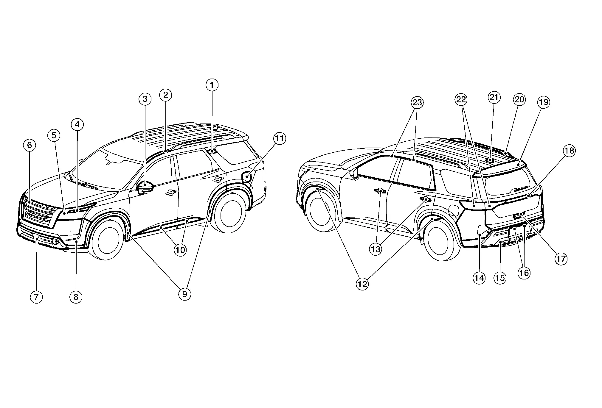
| Item | Component | Abbreviation | Material | |
|---|---|---|---|---|
| 1. | Rear pillar finisher (outer) | PMMA | Poly Methyl Methacrylate | |
| 2. | Roof side molding | PVC | Poly Vinyl Chloride | |
| 3. | Door mirror | Rear finisher | ABS | Acrylonitrile Butadiene Styrene |
| Housing | ASA | Acrylonitrile Styrene Acrylate | ||
| Finisher | ASA | Acrylonitrile Styrene Acrylate | ||
| 4. | Grille molding | ABS | Acrylonitrile Butadiene Styrene | |
| 5. | Front combination lamp | Lens | PC | Polycarbonate |
| Housing | PP | Polypropylene | ||
| 6. | Front grille | Inner | ABS | Acrylonitrile Butadiene Styrene |
| Outer | ABS | Acrylonitrile Butadiene Styrene | ||
| 7. | Front air spoiler (upper) | PP + EPDM | Polypropylene + Ethylene Propylene Diene Copolymer | |
| 8. | Front bumper fascia | PP + EPM | Polypropylene + Ethylene Propylene Copolymer | |
| 9. | Over fender | TPO | Thermoplastic Olefine | |
| 10. | Door outside lower molding | Body | TPO | Thermoplastic Olefine |
| Insert (if equipped) | ABS | Acrylonitrile Butadiene Styrene | ||
| 11. | Fuel filler lid | PA + PPE | Polyamide + Poly Phenylene Ether | |
| 12. | Fender protector | PP | Polypropylene | |
| 13. | Door outside handle | Body | PC + PET | Polycarbonate + Polyethylene Terephthalate |
| Escutcheon | PC + PET | Polycarbonate + Polyethylene Terephthalate | ||
| Cover | PC + AES | Polycarbonate + Acrylonitrile Ethylene Styrene | ||
| 14. | Rear bumper fascia | PP | Polypropylene | |
| 15. | Rear bumper finisher (lower) | PP | Polypropylene | |
| 16. | License plate lamp | Lens | PMMA | Poly Methyl Methacrylate |
| Housing | PC + ABS | Polycarbonate + Acrylonitrile Butadiene Styrene | ||
| 17. | Back door outside handle | PC + PET | Polycarbonate + Polyethylene Terephthalate | |
| 18. | Back door outer finisher | PC + ABS | Polycarbonate + Acrylonitrile Butadiene Styrene | |
| 19. | Rear spoiler | Upper | PC + ABS | Polycarbonate + Acrylonitrile Butadiene Styrene |
| Lower | ASA | Acrylonitrile Styrene Acrylate | ||
| 20. | Roof rack | Cover | ABS | Acrylonitrile Butadiene Styrene |
| Bar | Aluminum | – | ||
| 21. | Antenna base | PC + ABS | Polycarbonate + Acrylonitrile Butadiene Styrene | |
| 22. | Rear combination lamp | Lens | PMMA | Poly Methyl Methacrylate |
| Housing | ASA | Acrylonitrile Styrene Acrylate | ||
| 23. | Door outside molding | PVC | Poly Vinyl Chloride | |
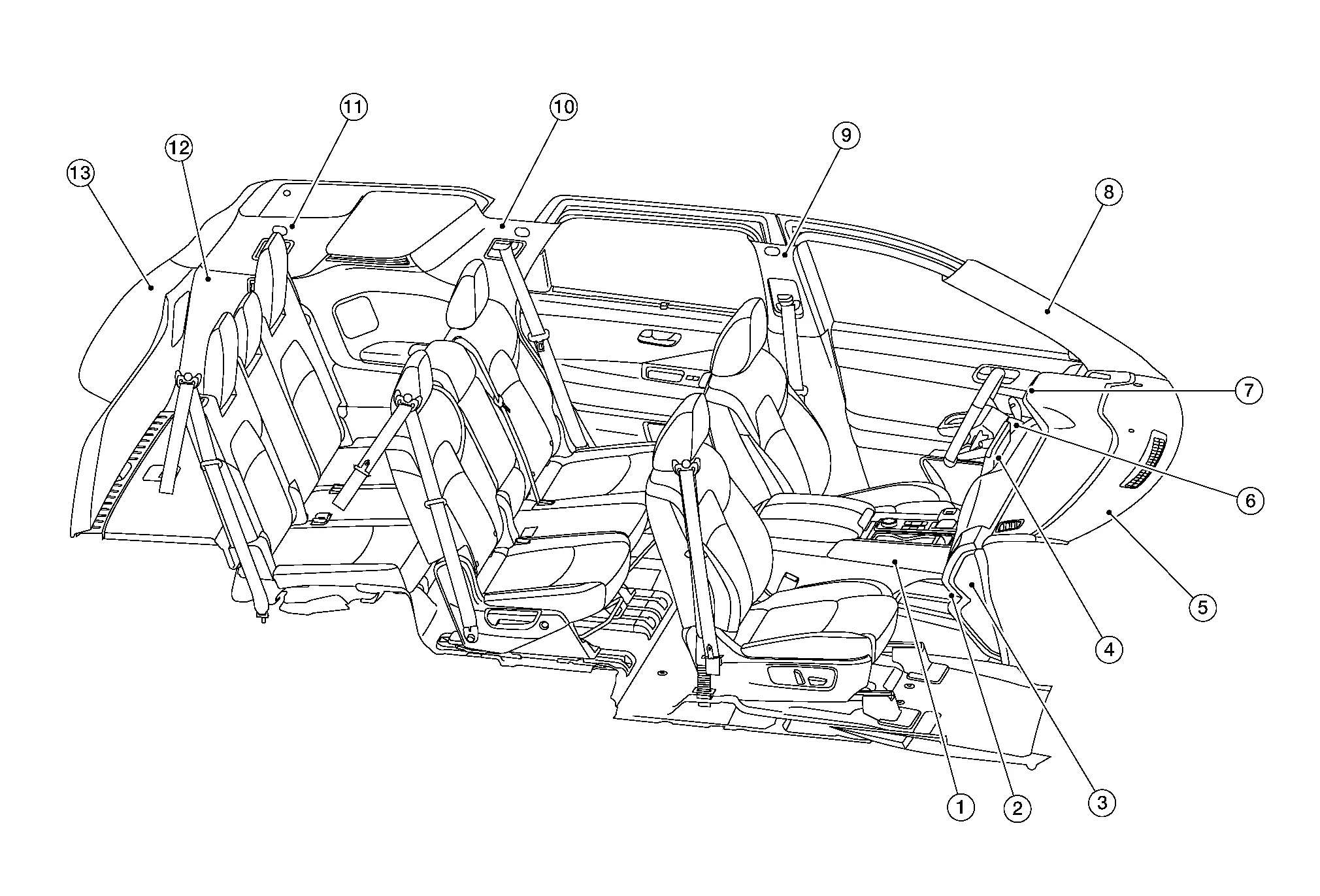
| Item | Component | Abbreviation | Material | |
|---|---|---|---|---|
| 1. | Center console assembly | Inner | PPC | Polypropylene Composite |
| Outer | ABS + PC | Acrylonitrile Butadiene Styrene + Polycarbonate | ||
| Tray | PPC | Polypropylene Composite | ||
| Housing | PP | Polypropylene | ||
| Lid insert | ABS | Acrylonitrile Butadiene Styrene | ||
| Lid cushion | PUR | Polyurethane | ||
| Lid plate | PPC | Polypropylene Composite | ||
| Lid inner | PPC | Polypropylene Composite | ||
| 2. | Glove box lid | Outer | PPC | Polypropylene Composite |
| Inner | PPC | Polypropylene Composite | ||
| 3. | Instrument side finisher | PPC | Polypropylene Composite | |
| 4. | Cluster lid C | ABS + PC | Acrylonitrile Butadiene Styrene + Polycarbonate | |
| Cluster lid D | ABS + PC | Acrylonitrile Butadiene Styrene + Polycarbonate | ||
| Cluster lid E | PPC | Polypropylene Composite | ||
| 5. | Instrument panel | Housing | PPC | Polypropylene Composite |
| Skin | TPO | Thermoplastic Olefine | ||
| Instrument finisher A | PPC | Polypropylene Composite | ||
| Instrument finisher B | PPC | Polypropylene Composite | ||
| Instrument lower panel LH | PPC | Polypropylene Composite | ||
| 6. | Steering column covers | PPC | Polypropylene Composite | |
| 7. | Cluster lid A | Housing | PPC | Polypropylene Composite |
| Ring | ABS + PC | Acrylonitrile Butadiene Styrene + Polycarbonate | ||
| 8. | Front pillar finisher | PPC | Polypropylene Composite | |
| 9. | Center pillar finisher | Upper | PP | Polypropylene |
| Lower | PP | Polypropylene | ||
| 10. | Rear pillar finisher | PP | Polypropylene | |
| 11. | Back pillar finisher | PP | Polypropylene | |
| 12. | Luggage side lower finisher | PP | Polypropylene | |
| 13. | Back door finisher | Upper | PP | Polypropylene |
| Lower | PP | Polypropylene | ||
| Sides | PP | Polypropylene | ||
Repairing High Strength Steel Nissan Pathfinder 5th Gen
High Strength Steel (HSS)
High strength steel is used for body panels in order to reduce vehicle weight.
Accordingly, precautions in repairing automotive bodies made of high strength steel are described below:
| Tensile strength | Major applicable parts |
|---|---|
| 440 – 780 MPa |
|
| 980 - 1350 MPa |
|
Read the following precautions when repairing HSS:
-
Additional points to consider:
-
The repair of reinforcements (such as side members) by heating is not recommended since it may weaken the component. When heating is unavoidable, do not heat HSS parts above 550°C (1,022°F).
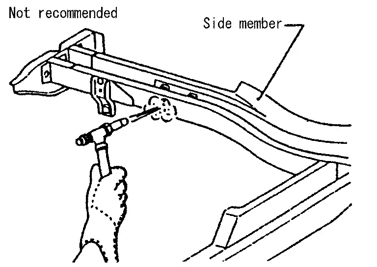
Verify heating temperature with a thermometer.
(Crayon-type and other similar type thermometers are appropriate.)
-
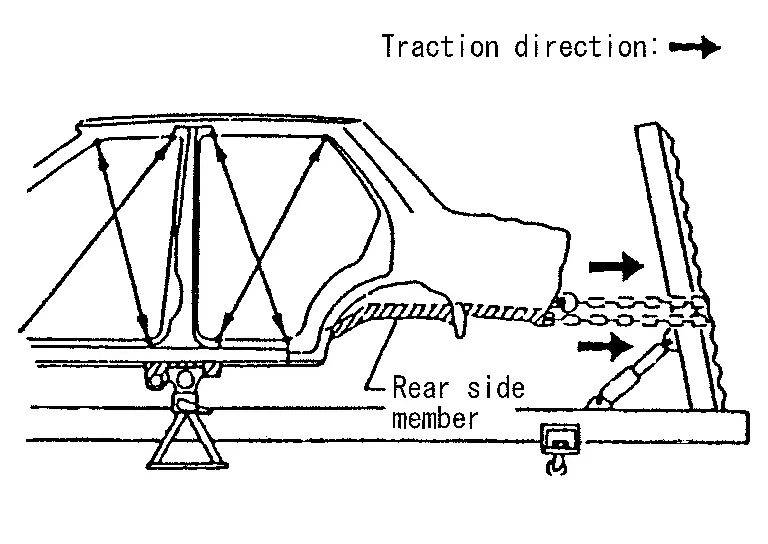
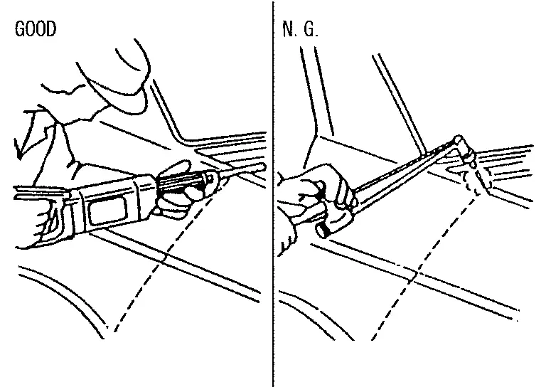
When straightening body panels, use caution in pulling any HSS panel. Because HSS is very strong, pulling may cause deformation in adjacent portions of the body. In this case, increase the number of measuring points and carefully pull the HSS panel.
-
When cutting HSS panels, avoid gas (torch) cutting if possible. Instead, use a saw to avoid weakening surrounding areas due to heat. If gas (torch) cutting is unavoidable, allow a minimum margin of 50 mm (1.97 in).
-
When welding HSS panels, use spot welding whenever possible in order to minimize weakening surrounding areas due to heat.
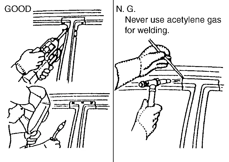
If spot welding is impossible, use MAG. welding. Do not use gas (torch) for welding because it is inferior in welding strength.
-
The spot weld on HSS panels is harder than that of an ordinary steel panel.
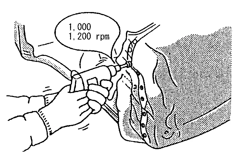
Therefore, when cutting spot welds on a HSS panel, use a low speed high torque drill (1,000 to 1,200 rpm) to increase drill bit durability and facilitate the operation.
-
-
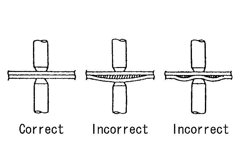
Precautions in spot welding HSS
This work should be performed under standard working conditions. Always note the following when spot welding HSS:
-
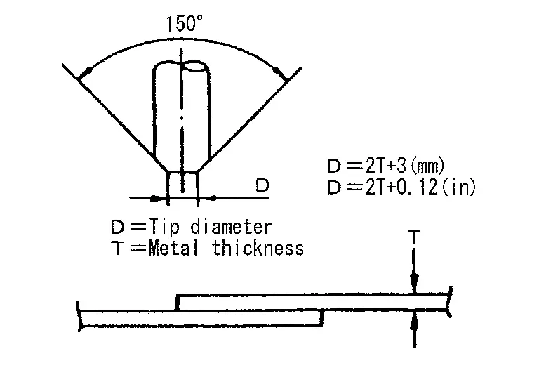
The electrode tip diameter must be sized properly according to the metal thickness.
-
The panel surfaces must fit flush to each other, leaving no gaps.
-
Follow the specifications for the proper welding pitch.
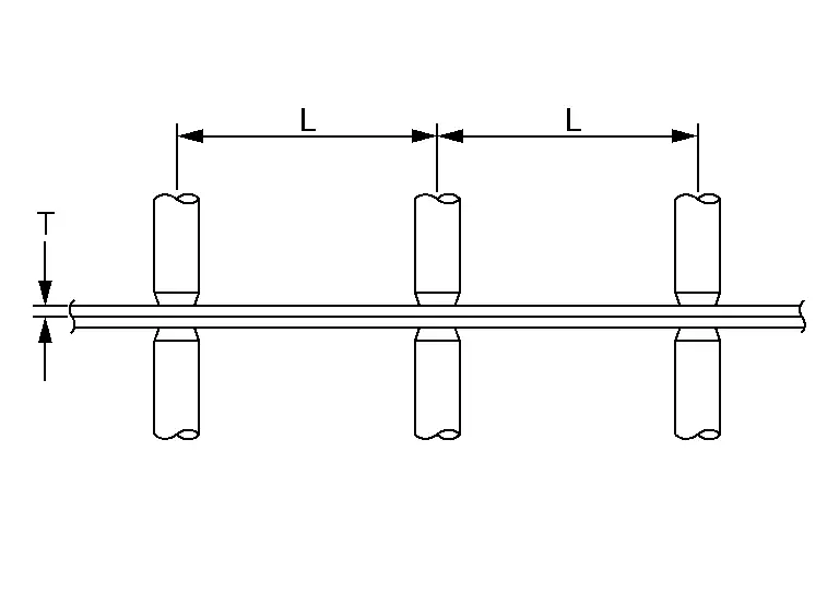
Unit: mm (in)
Thickness (T) Minimum pitch (L) 0.6 (0.024)
0.8 (0.031)
1.0 (0.039)
1.2 (0.047)
1.6 (0.063)
1.8 (0.071)10 (0.39) or over
12 (0.47) or over
18 (0.71) or over
20 (0.79) or over
27 (1.06) or over
31 (1.22) or over
-
Handling of Ultra High Strength Steel Plate Parts
PROHIBITION OF CUT AND CONNECTION
Do not cut and join the lower lock pillar reinforcement (center pillar reinforcement inside frame parts) because its material is high strength steel plate (ultra high strength steel plate).
The center pillar reinforcement must be replaced if this part is damaged.
Welding of Ultra High Strength Steel
SPOT WELDING
Spot welding is limited to ultra high strength steel of (tensile strength: 980 MPa) according to the welding conditions listed below.
CAUTION:
-
If the below welding conditions cannot be met, then perform plug welding.
-
Never spot weld ultra high strength steel of tensile strength more than 980 MPa. For this type of ultra high strength steel, perform plug welding.
-
The below welding condition is applicable only to this Nissan Pathfinder vehicle. Never apply these same conditions to other vehicles.
| Welder tip diameter | 6 MM | |
| Welding pressure (Gun force) | 3425 N | |
| Welding current | 8600 A | |
| Weld time* |
.24 sec (12 cyc: 50 Hz) .23 sec (14 cyc: 60 Hz) |
|
| Panel configuration | Combination of a plate of tensile strength of 980 MPa and that of tensile strength less than 980 MPa. (Up to 3 plates) | |
| * Select weld time based on the frequency (Hz) of the electrical power supplied in your area. | ||
PLUG WELDING
To weld ultra high strength steel of tensile strength 980 MPa or more, perform plug welding observing the welding hole diameter described in the manual.
CAUTION:
-
To perform plug welding, use fuel mixture (Ar 80% + CO2 20%) for shielding gas of welder.
-
Never use carbon dioxide gas (CO2 100%) as shielding gas of welder. Using CO2 100% gas results in inadequate weld strength.
-
When welding hole diameter cannot be met, make multiple holes (smaller diameter) so that the sum of the holes areas equals the area of the original weld hole.

Nissan Pathfinder (R53) 2022-2026 Service Manual
Precaution
Contact Us
Nissan Pathfinder Info Center
Email: info@nipathfinder.com
Phone: +1 (800) 123-4567
Address: 123 Pathfinder Blvd, Nashville, TN 37214, USA
Working Hours: Mon–Fri, 9:00 AM – 5:00 PM (EST)
