Nissan Pathfinder: Door & Lock - Hood
Exploded View
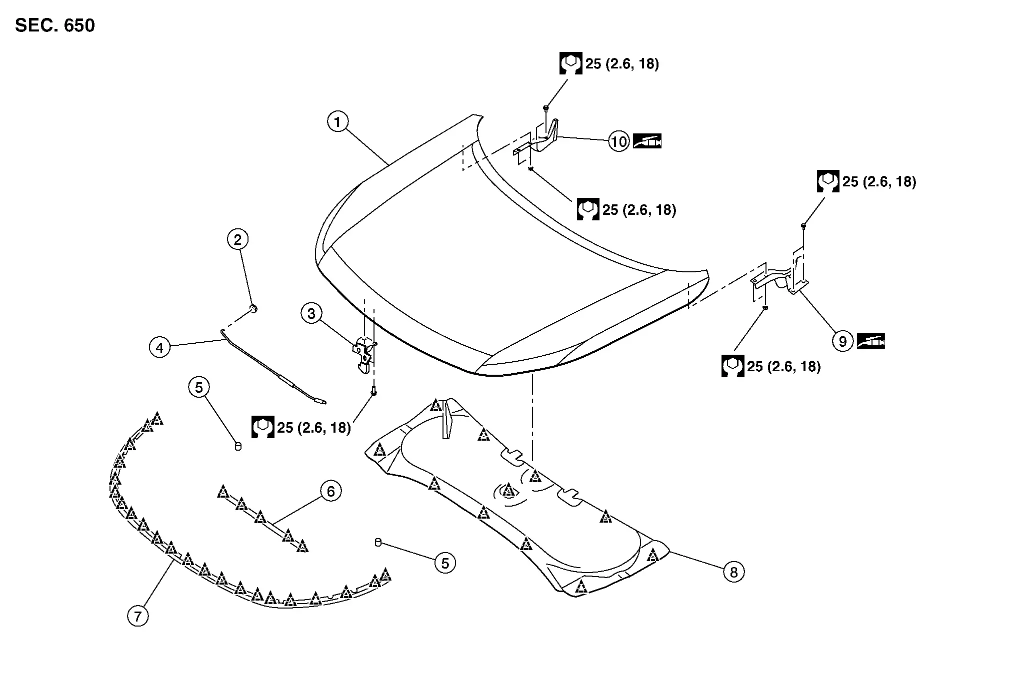
| 1. | Hood | 2. | Hood support rod grommet | 3. | Hood secondary latch |
| 4. | Hood support rod | 5. | Bumper rubber | 6. | Radiator core seal |
| 7. | Hood seal | 8. | Hood insulator | 9. | Hood hinge (LH) |
| 10. | Hood hinge (RH) |
 |
: Clip |
Hood Assembly Nissan Pathfinder R53
Removal and Installation
CAUTION:
-
Use two people when removing or installing hood assembly due to it’s heavy weight.
-
Use protective tape or shop cloths to protect surrounding components from damage during removal and installation of hood assembly.
REMOVAL
Support hood assembly using a suitable tool.
WARNING:
Bodily injury may occur if hood assembly is not supported properly when removing hood assembly.
Remove washer tube from hood assembly. Refer to Exploded View.
Remove hood assembly mounting nuts, and then remove hood assembly.
INSTALLATION
Note the following items, and then install in the reverse order of removal.
CAUTION:
-
Before installation, apply anticorrosive agent onto mounting surface.
-
After installation, perform the fitting adjustment. Refer to Adjustment.
Adjustment
WITHOUT ROCK CREEK®
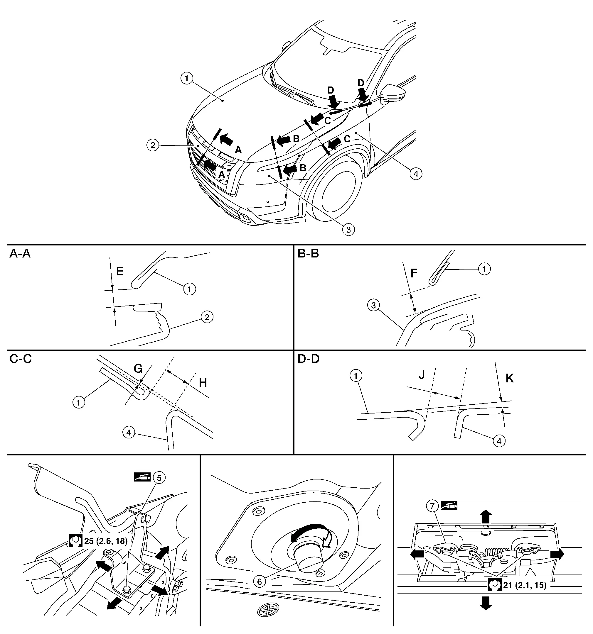
| 1. | Hood | 2. | Front grill | 3. | Front combination lamp |
| 4. | Front fender | 5. | Hood hinge | 6. | Hood bumper rubber |
| 7. | Hood lock |
Check the clearance and the surface height between hood and each part by visual inspection and tactical feel.
If the clearance and the surface height are out of specification, adjust them according to the adjustment procedures.
Unit: mm (in)
| Portion | Standard | Parallelism | |||
|---|---|---|---|---|---|
| Hood – Front grill | A – A | E | Clearance | 6.0 ± 2.5 (0.236 ± 0.098) | < 3.0 [0.118] |
| Hood – Front combination lamp | B – B | F | Clearance | 6.0 ± 2.0 (0.236 ± 0.079) | < 3.9 [0.154] |
| Hood – Front fender | C – C | G | Surface height | 0.5 ± 1.5 (0.020 ± 0.059) | < 2.0 [0.079] |
| H | Clearance | 5.0 ± 2.0 (0.20 ± 0.08) | < 2.0 (0.08) | ||
| Hood – Front fender | D– D | J | Clearance | 5.1 ± 1.0 (0.201 ± 0.039) | < 1.5 [0.059] |
| K | Surface height | 0.0 ± 1.5 (0.00 ± 0.059) | — | ||
WITH ROCK CREEK®
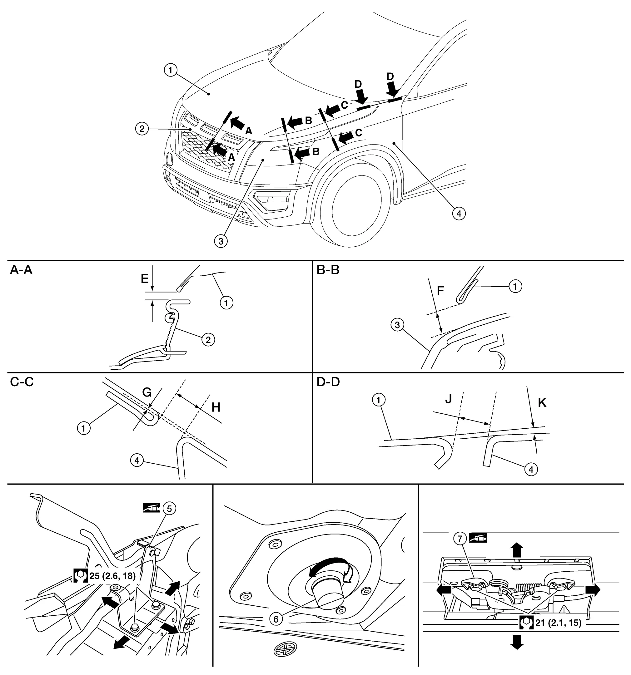
| 1. | Hood | 2. | Front grill | 3. | Front combination lamp |
| 4. | Front fender | 5. | Hood hinge | 6. | Hood bumper rubber |
| 7. | Hood lock |
Check the clearance and the surface height between hood and each part by visual inspection and tactical feel.
If the clearance and the surface height are out of specification, adjust them according to the adjustment procedures.
Unit: mm (in)
| Portion | Standard | Parallelism | |||
|---|---|---|---|---|---|
| Hood – Front grill | A – A | E | Clearance | 6.0 ± 2.0 (0.236 ± 0.079) | ≤ 3.0 [0.118] |
| Hood – Front combination lamp | B – B | F | Clearance | 6.0 ± 2.0 (0.236 ± 0.079) | < 3.9 [0.154] |
| Hood – Front fender | C – C | G | Surface height | 0.5 ± 1.5 (0.020 ± 0.059) | < 2.0 [0.079] |
| H | Clearance | 5.0 ± 2.0 (0.20 ± 0.08) | < 2.0 (0.08) | ||
| Hood – Front fender | D– D | J | Clearance | 5.1 ± 1.0 (0.201 ± 0.039) | < 1.5 [0.059] |
| K | Surface height | 0.0 ± 1.5 (0.00 ± 0.059) | — | ||
HEIGHT ADJUSTMENT
Loosen the hood lock bolts.
Adjust the surface height of hood to front bumper fascia and front fender according to the specified values by rotating hood bumper rubber.
Temporarily tighten hood lock bolts.
Adjust (A) and (B) as shown to the following value with hood's own weight by dropping it from approximately 200 mm (7.87 in) height.
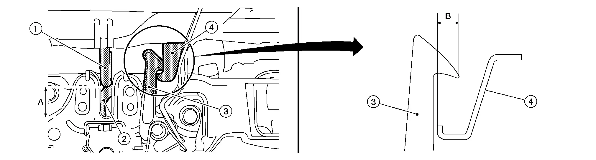
| 1. | Primary striker | 2. | Primary latch | 3. | Secondary latch |
| 4. | Secondary striker | A. | 20 mm (0.79 in) | B. | 6.8 mm (0.27 in) |
After adjustment, tighten hood hinge nuts and bolts to the specified torque.
CAUTION:
-
Check hood hinge rotating part for poor lubrication. If necessary, apply a suitable multi-purpose grease.
-
After adjusting, apply touch-up paint (body color) onto the head of hood hinge bolts and nuts.
CLEARANCE ADJUSTMENT
Loosen hood hinge nuts and bolts.
Loosen the hood lock bolts.
Adjust the hood so the clearance measurements are within specifications.
Tighten the hood hinge nuts and bolts to specified torque.
Tighten the hood lock bolts to specified torque.
Hood Hinge Nissan Pathfinder 2026
Removal and Installation
REMOVAL
Remove hood assembly. Refer to Removal and Installation.
Remove front fender. Refer to Removal and Installation.
Remove hood hinge mounting bolts, and then remove hood hinge.
INSTALLATION
Installation is in the reverse order of removal.
CAUTION:
-
Before installing hood hinge, apply anticorrosive agent onto surface of Nissan Pathfinder vehicle.
-
After installation, perform hood assembly adjustment procedure. Refer to Adjustment.
Hood Support Rod Nissan Pathfinder 2026
Removal and Installation
REMOVAL
CAUTION:
Support hood with a proper material and use protective tape or shop cloth to protect hood and body from falling and damage when removing and installing hood support rod.
Support hood assembly with a suitable material to prevent it from falling.
CAUTION:
Injury may occur if hood assembly is not supported with a proper material when removing hood assembly.
Remove hood support rod from hood support rod grommet.
Disengage hood support rod grommet fixing pawls, and then remove hood support rod grommet from radiator core support.
INSTALLATION
Installation is in the reverse order of removal.

Nissan Pathfinder (R53) 2022-2026 Service Manual
Hood
Contact Us
Nissan Pathfinder Info Center
Email: info@nipathfinder.com
Phone: +1 (800) 123-4567
Address: 123 Pathfinder Blvd, Nashville, TN 37214, USA
Working Hours: Mon–Fri, 9:00 AM – 5:00 PM (EST)
