Nissan Pathfinder: Front Axle - Front Drive Shaft Boot
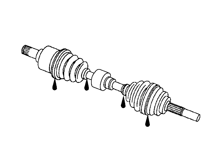
Exploded View
LH
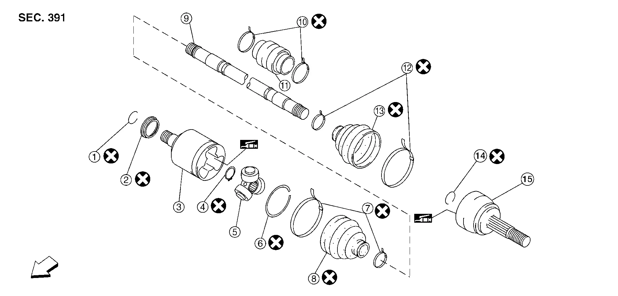
| 1. | Circlip | 2. | Dust shield | 3. | Slide joint housing |
| 4. | Snap ring | 5. | Spider assembly | 6. | Stopper ring |
| 7. | Boot band | 8. | Boot | 9. | Shaft |
| 10. | Damper band | 11. | Damper | 12. | Boot band |
| 13. | Boot | 14. | Circlip | 15. | Joint sub-assembly |
 |
Front |
RH
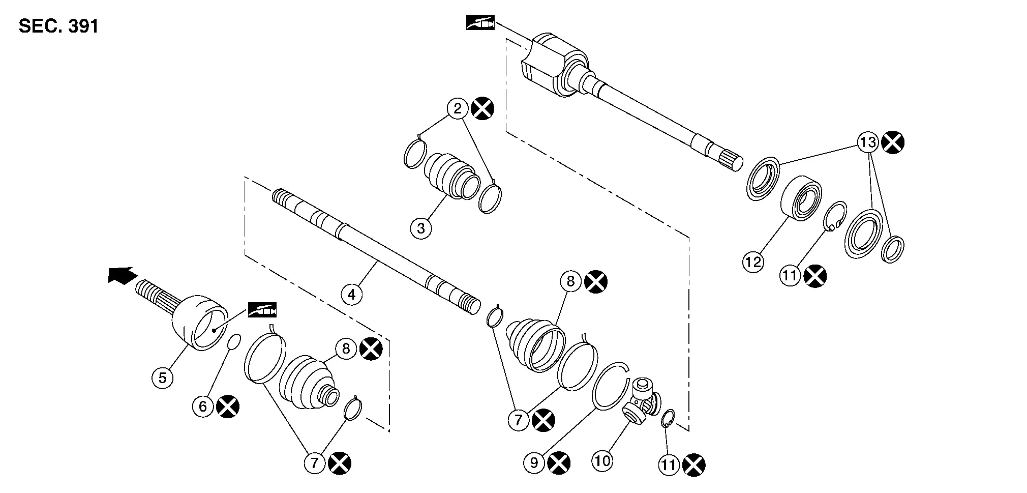
| 1. | Housing | 2. | Damper bands | 3. | Dynamic damper |
| 4. | Shaft | 5. | Joint sub-assembly | 6. | Circular clip |
| 7. | Boot bands | 8. | Boot | 9. | Stopper ring |
| 10. | Spider assembly | 11. | Snap ring | 12. | Support bearing |
| 13. | Dust shield |
 |
Wheel side | ||
 |
Fill NISSAN Genuine grease or equivalent. | ||||
Wheel Side Nissan Pathfinder Fifth generation
Removal and Installation
REMOVAL
Remove front disc brake rotor. Refer to Removal and Installation.
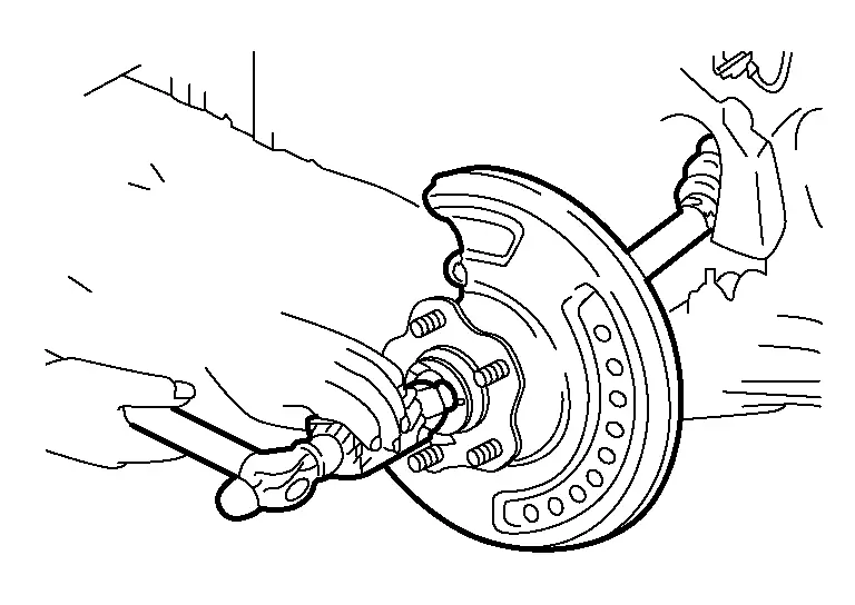
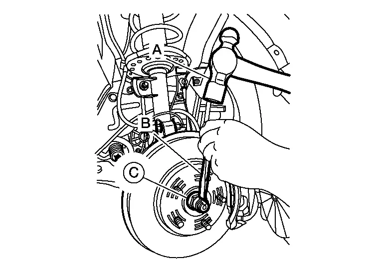
Using suitable tool (A) and Tool (B) release staked area (C) of wheel hub lock nut (D).
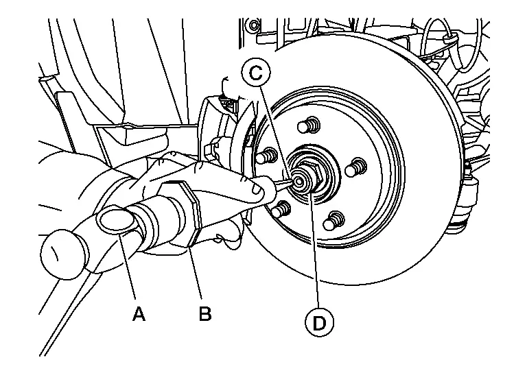
| Tool number (B) | : (NI-52982) |
Visually verify that staked area (A) of wheel hub lock nut (B) is completely released from front drive shaft (1) or damage to drive shaft can occur.
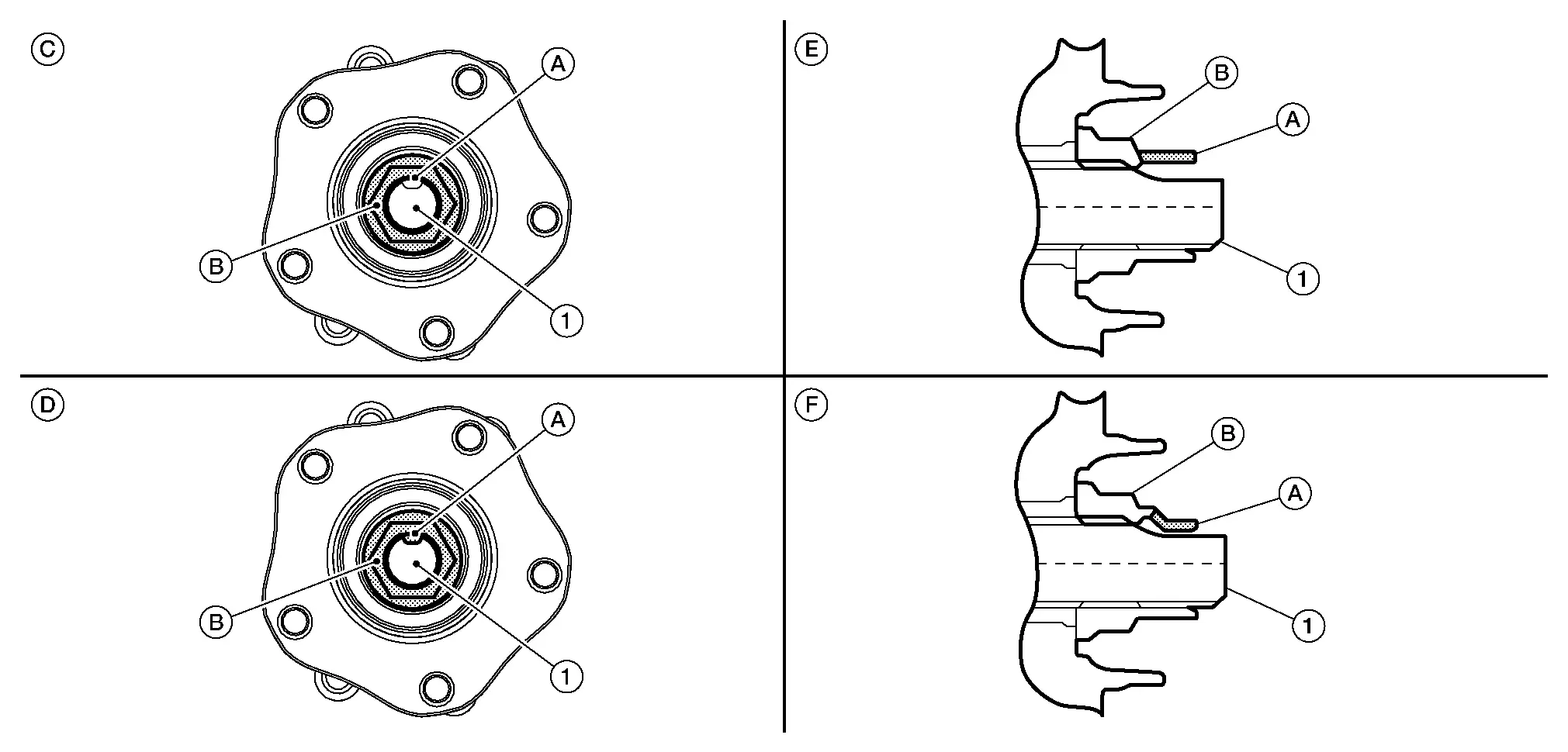
| (C) | : Fully released |
| (D) | : Not fully released |
| (E) | : Fully released (sectional view) |
| (F) | : Not fully released (sectional view) |
WARNING:
To avoid risk of death or severe personal injury:
-
Be sure that staked area of wheel hub lock nut is fully released or damage to drive shaft can occur.
-
Do not damage front drive shaft threads.
Loosen wheel hub lock nut from drive shaft.
WARNING:
To avoid risk of death or severe personal injury:
-
Do not use power tool.
-
Do not damage front drive shaft threads.
-
Do not reuse drive shaft lock nut.
-
When loosening lock nut, if it does not turn smoothly, verify that staked area is completely released.
Using a piece of wood and a suitable tool, tap on the lock nut to disengage drive shaft from wheel hub.
WARNING:
To avoid risk of death or severe personal injury:
-
Do not place drive shaft joint at an extreme angle. Be careful not to over extend slide joint.
-
Do not allow drive shaft to hang without support.
 NOTE:
NOTE:
Use suitable puller if drive shaft cannot be separated from wheel hub and bearing assembly.
Remove wheel hub lock nut.
WARNING:
To avoid risk of death or severe personal injury:
-
Do not reuse wheel hub lock nut.
Remove boot bands.
Remove boot from joint sub-assembly.
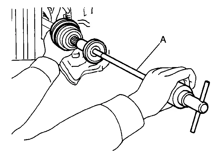
Screw sliding hammer or suitable tool (A) 30 mm (1.18 in) or more into threaded part of joint sub-assembly. Support drive shaft with one hand and pull out joint sub-assembly with a sliding hammer or suitable tool from housing assembly.
CAUTION:
-
Align sliding hammer or suitable tool and drive shaft and remove joint sub-assembly by pulling directly.
-
If joint sub-assembly cannot be removed after five or more unsuccessful attempts, replace the entire drive shaft assembly.
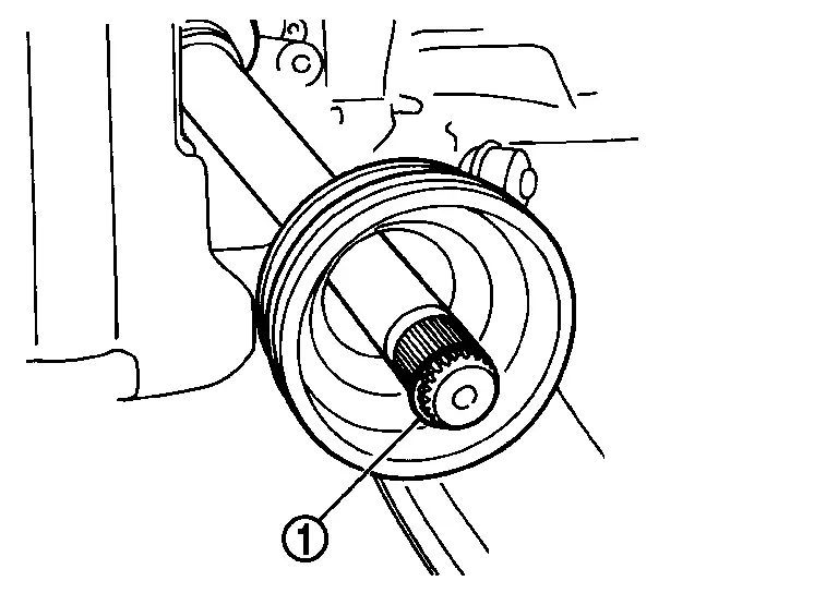
Remove circular clip (1) from housing assembly.
Remove boot from housing assembly.
Inspect the components. Refer to Inspection.
INSTALLATION
Clean the old grease on joint sub-assembly with paper shop cloth.
Fill serration slot joint sub-assembly with NISSAN genuine grease or equivalent.
CAUTION:
After applying grease, use a paper shop cloth to wipe off old grease that has oozed out.
Install boot and boot bands to housing assembly.
CAUTION:
-
Wrap serration on housing assembly with tape to protect the boot from damage.
-
Do not reuse boot and boot band.
Remove the tape wrapped around the serration on housing assembly.
Position the circular clip on groove at the housing assembly edge.
CAUTION:
Do not reuse circular clip.
Align both center axles of the housing assembly edge and joint sub-assembly. Install housing assembly with joint sub-assembly holding circular clip.
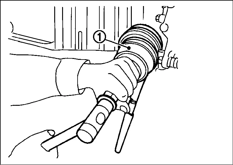
Install joint sub-assembly (1) to housing assembly using suitable tool.
WARNING:
Ensure that circular clip is properly engaged, otherwise the joint subassembly could pull away from transaxle during Nissan Pathfinder vehicle operation resulting in loss of drive force and possible drive shaft damage, which may cause a crash and serious injury or damage the drive shaft.
Pull the joint sub-assembly in the axial direction away from transaxle assembly. Confirm that the joint sub assembly cannot be pulled out.
Apply the specified amount of grease into the large diameter side opening of the boot.
| Grease amount | : Refer to Drive Shaft. |
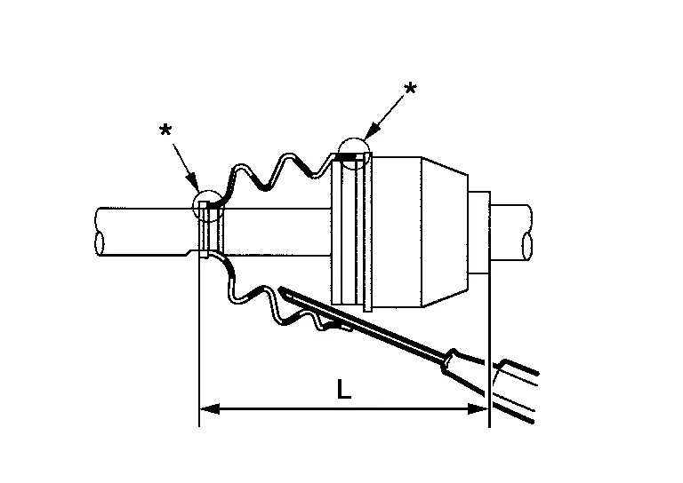
Install the boot securely into grooves (indicated by “*” marks) shown in the figure.
CAUTION:
If grease adheres to the boot mounting surface (indicated by “*” mark) on the housing assembly or joint sub-assembly, boot may come off. Remove all grease from the boot mounting surface.
Make sure boot installation length (L) is the specified length. Insert a suitable tool into the large end of boot. Bleed air from boot to prevent boot deformation.
| Boot installation length (L) | : Refer to Drive Shaft. |
CAUTION:
-
Boot may break if boot installation length is not within standard value.
-
Be careful that suitable tool does not contact inside surface of boot.
Install new large and small boot bands securely using Tool.
| Tool number | : KV40107300 (NI-51751) |
CAUTION:
Do not reuse boot band.
 NOTE:
NOTE:
Secure boot band so that dimension (M) meets the specification as shown.
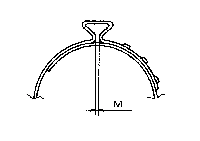
| Dimension (M) | : Refer to Boot Bands. |
Secure joint sub-assembly and housing assembly. Make sure that they are in the correct position when rotating boot. Reinstall them using boot bands when boot installation positions become incorrect.
CAUTION:
Do not reuse boot band.
Clean the mating surface of the wheel hub lock nut and the wheel hub and bearing.
CAUTION:
Do not apply lubricating oil to these mating surfaces.
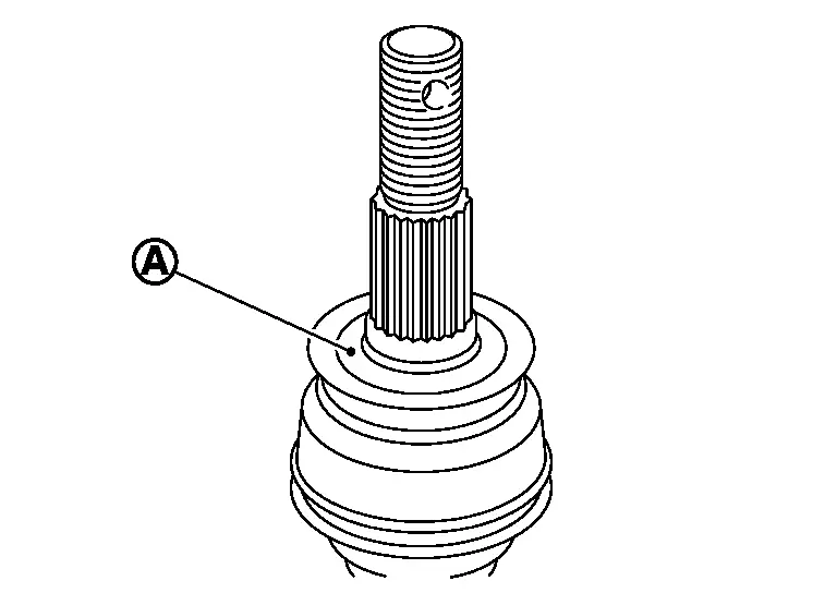
Clean the mating surface of the drive shaft (A) and the wheel hub and bearing.
Using suitable tool (A) and cold chisel (B) stake the wheel hub lock nut (C) as shown.
WARNING:
To avoid the risk of death or severe personal injury:
-
Use the following range when staking the wheel hub lock nut.
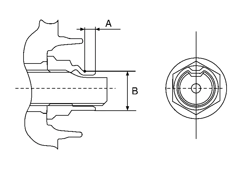
| (A) | : 6.2 mm (0.244 in) |
| (B) | : 26.4 - 27.8 mm (1.039 - 1.094 in) |
Install the remainder in reverse order of removal.
Transaxle Side Nissan Pathfinder
Removal and Installation
REMOVAL
Remove front drive shaft. Refer to Removal and Installation (LH) or Refer to Removal and Installation (RH).
Secure front drive shaft in a vise.
CAUTION:
When securing shaft in a vise, always use copper or aluminum plates between vise and shaft.
Remove boot bands and slide boot back.
CAUTION:
Do not reuse boot bands.
Put matching marks on the slide joint housing and shaft before separating the slide joint housing.
CAUTION:
Use paint or an equivalent for matching marks. Do not scratch surfaces.
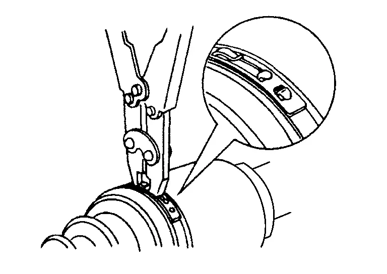
Remove stopper ring using a suitable tool.
![]()
CAUTION:
Do not reuse stopper ring.
Pull out slide joint housing.
Put matching marks (A) on spider assembly and shaft.
![]()
CAUTION:
Use paint or an equivalent for matching marks. Do not scratch surfaces.
Remove snap ring (1) using a suitable tool.
CAUTION:
Do not reuse stopper ring.
![]()
Remove spider assembly from shaft.
Remove boot from shaft.
CAUTION:
Do not reuse boot.
Remove circular clip from slide joint housing.
CAUTION:
Do not reuse circular clip.
Remove dust shield from slide joint housing.
CAUTION:
Do not reuse dust shield.
Clean old grease off slide joint housing.
INSTALLATION
Clean the old grease on joint sub-assembly with paper shop cloth.
Fill serration slot joint sub-assembly with NISSAN genuine grease or equivalent.
CAUTION:
After applying grease, use a paper shop cloth to wipe off old grease that has oozed out.
Install boot and boot bands to housing assembly.
CAUTION:
-
Wrap serration on housing assembly with tape to protect the boot from damage.
-
Do not reuse boot and boot band.
Remove the tape wrapped around the serration on housing assembly.
Position the circular clip on groove at the housing assembly edge.
CAUTION:
Do not reuse circular clip.
Align both center axles of the housing assembly edge and joint sub-assembly. Install housing assembly with joint sub-assembly holding circular clip.
Install joint sub-assembly (1) to housing assembly using suitable tool.
![]()
WARNING:
Ensure that circular clip is properly engaged, otherwise the joint subassembly could pull away from transaxle during Nissan Pathfinder vehicle operation resulting in loss of drive force and possible drive shaft damage, which may cause a crash and serious injury or damage the drive shaft.
Pull the joint sub-assembly in the axial direction away from transaxle assembly. Confirm that the joint sub assembly cannot be pulled out.
Apply the specified amount of grease into the large diameter side opening of the boot.
| Grease amount | : Refer to Drive Shaft. |
Install the boot securely into grooves (indicated by “*” marks) shown in the figure.
![]()
CAUTION:
If grease adheres to the boot mounting surface (indicated by “*” mark) on the housing assembly or joint sub-assembly, boot may come off. Remove all grease from the boot mounting surface.
Make sure boot installation length (L) is the specified length. Insert a suitable tool into the large end of boot. Bleed air from boot to prevent boot deformation.
| Boot installation length (L) | : Refer to Drive Shaft. |
CAUTION:
-
Boot may break if boot installation length is not within standard value.
-
Be careful that suitable tool does not contact inside surface of boot.
Install new large and small boot bands securely using Tool.
![]()
| Tool number | : KV40107300 (NI-51751) |
CAUTION:
Do not reuse boot band.
![]() NOTE:
NOTE:
Secure boot band so that dimension (M) meets the specification as shown.
![]()
| Dimension (M) | : Refer to Boot Bands. |
Secure joint sub-assembly and housing assembly. Make sure that they are in the correct position when rotating boot. Reinstall them using boot bands when boot installation positions become incorrect.
CAUTION:
Do not reuse boot band.
Clean the mating surface of the wheel hub lock nut and the wheel hub and bearing.
CAUTION:
Do not apply lubricating oil to these mating surfaces.
Clean the mating surface of the drive shaft (A) and the wheel hub and bearing.
![]()
Install the remainder in reverse order of removal.
Inspection
Inspection After Removal
-
Move joint up/down, left/right, and in the axial directions. Check for motion that is not smooth and for significant looseness.
-
Check boot for cracks, damage, and leakage of grease.
-
Disassemble drive shaft and exchange malfunctioning part if there is a non-standard condition.

Nissan Pathfinder (R53) 2022-2026 Service Manual
Front Drive Shaft Boot
Contact Us
Nissan Pathfinder Info Center
Email: info@nipathfinder.com
Phone: +1 (800) 123-4567
Address: 123 Pathfinder Blvd, Nashville, TN 37214, USA
Working Hours: Mon–Fri, 9:00 AM – 5:00 PM (EST)
