Nissan Pathfinder: Door & Lock - Front Door
Exploded View
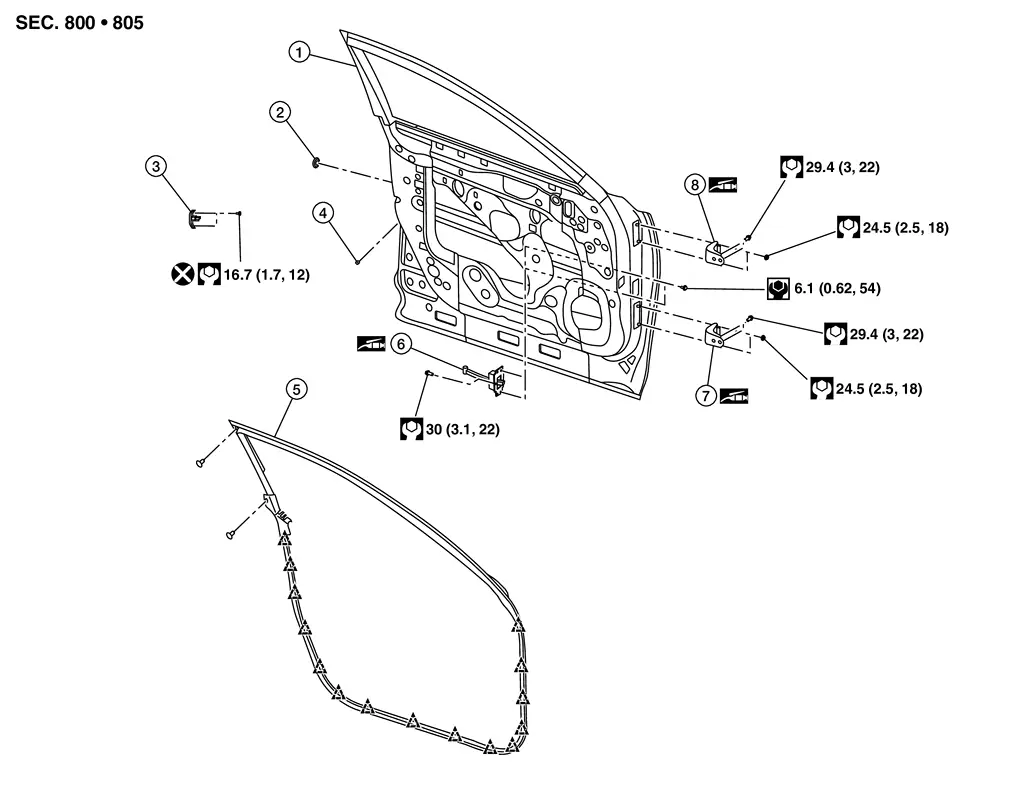
| 1. | Front door | 2. | Grommet | 3. | Front door striker |
| 4. | Rubber bumper | 5. | Front door weatherstrip | 6. | Front door check link |
| 7. | Front door hinge (lower) | 8. | Front door hinge (upper) |
 |
: Clip |
Front Door Assembly Nissan Pathfinder R53
Removal and Installation
CAUTION:
-
Use two people when removing or installing the front door due to it’s heavy weight.
-
When removing and installing door assembly, support front door with a suitable tool.
REMOVAL
Disconnect negative and positive battery terminals, then wait at least three minutes. Refer to Battery Disconnect.
Disconnect the harness connector from the front door (1) and remove from the [(body side) (2)].
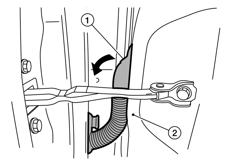
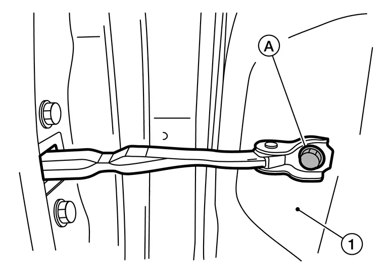
Remove door check link bolt (A) from the [(body side) (1)].
Remove front door hinge nuts from (door side) and remove front door.
INSTALLATION
Installation is in the reverse order of removal.
CAUTION:
-
Apply anticorrosive agent onto the surface.
-
After installation, check front door open/close and lock/unlock operation. Refer to Adjustment.
-
After installation, perform the front door adjustment procedure. Refer to Adjustment.
-
Perform camera image calibration (with intelligent around view monitor). Refer to Work Procedure.
Adjustment
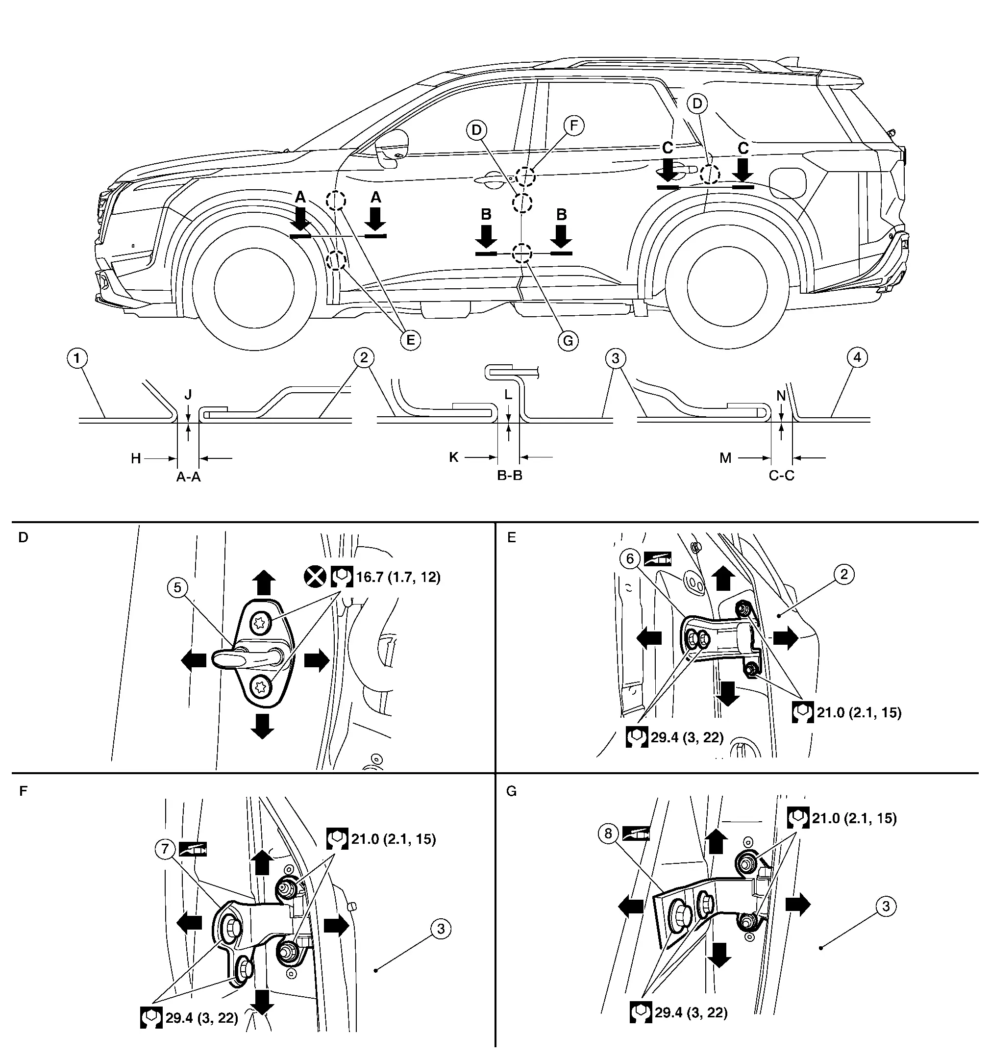
| 1. | Front fender assembly | 2. | Front door panel | 3. | Rear door panel |
| 4. | Body side outer | 5. | Door striker | 6. | Front door hinge |
| 7. | Rear door upper hinge | 8. | Rear door lower hinge |
Unit: mm (in)
| Portion | Standard | |||
|---|---|---|---|---|
| Front door panel – Front fender assembly | A – A | H | Clearance |
3.0 – 5.0 [0.118 – 0.197] |
| J | Surface height |
(-1.0) – (+1.0) [(-0.039) – (+0.039)] |
||
| Front door panel – Rear door panel | B – B | K | Clearance |
3.5 – 5.5 [0.138 – 0.217] |
| L | Surface Height |
(-1.0) – (+1.0) [(-0.039) – (+0.039)] |
||
| Rear door panel – Body side outer | C – C | M | Clearance |
3.3 – 5.3 [0.130 – 0.209] |
| N | Surface height |
(-1.0) – (+1.0) [(-0.039) – (+0.039)] |
||
Check the clearance and surface height between front door and each part by visually looking and touching.
If the clearance and the surface height are out of specification, adjust them according to the procedures shown below.
Remove front fender. Refer to Removal and Installation.
Loosen front door hinge nuts (door side).
Adjust the surface height of front door according to the specifications provided.
Temporarily tighten front door hinge nuts (door side).
Loosen front door hinge bolts (body side).
Raise front door at rear end to adjust clearance of the front door according to the specifications provided.
After adjustment tighten bolts and nuts to the specified torque.
CAUTION:
-
Check door hinge rotating point for poor lubrication. If necessary, apply a suitable multi-purpose grease.
-
After adjusting, apply touch-up paint (body color) to the head of front door hinge bolts and nuts.
Install front fender. Refer to refer to Removal and Installation.
Front Door Striker Nissan Pathfinder
Removal and Installation
REMOVAL
Remove front door striker bolts.
CAUTION:
Do not reuse front door striker bolts.
Remove front door striker.
INSTALLATION
Installation is in the reverse order of removal.
CAUTION:
-
Do not reuse front door striker bolts.
-
After installation, perform the front door adjustment procedure. Refer to Adjustment.
-
Perform camera image calibration (with Intelligent Around View Monitor). Refer to Work Procedure.
Adjustment
DOOR STRIKER ADJUSTMENT
Loosen door striker bolts.
Adjust door striker so that it becomes parallel with front door lock insertion direction.
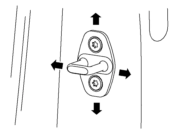
CAUTION:
Tighten bolts to specified torque. Refer to Exploded View.
Front Door Hinge Nissan Pathfinder R53
Removal and Installation
REMOVAL
Remove front door. Refer to Removal and Installation.
Remove front fender. Refer to Removal and Installation.
Remove front door hinge bolts, and then remove front door hinge.
INSTALLATION
Note the following items, and then install in the reverse order of removal.
CAUTION:
-
Apply anticorrosive agent onto the hinge mating surface.
-
After installation, check front door open/close and lock/unlock operation.
-
Check door hinge rotating point for poor lubrication. If necessary, apply a suitable multi-purpose grease.
-
After installation, perform the front door adjustment procedure. Refer to Adjustment.
Front Door Check Link Nissan Pathfinder R53
Removal and Installation
REMOVAL
Fully close front door window.
Remove front door speaker. Refer to Removal and installation.
Remove door check link bolt (body side).
Remove door check link bolts (door side).
Remove door check link through hole in door.
INSTALLATION
Installation is in the reverse order of removal.
CAUTION:
-
Tighten nuts/bolts to specified torque. Refer to Exploded View.
-
After installation, check front door open/close and lock/unlock operation.
-
Check door check link rotating point for poor lubrication. If necessary, apply a suitable multi-purpose grease.

Nissan Pathfinder (R53) 2022-2026 Service Manual
Front Door
Contact Us
Nissan Pathfinder Info Center
Email: info@nipathfinder.com
Phone: +1 (800) 123-4567
Address: 123 Pathfinder Blvd, Nashville, TN 37214, USA
Working Hours: Mon–Fri, 9:00 AM – 5:00 PM (EST)
