Nissan Pathfinder: Door & Lock - Back Door
Exploded View
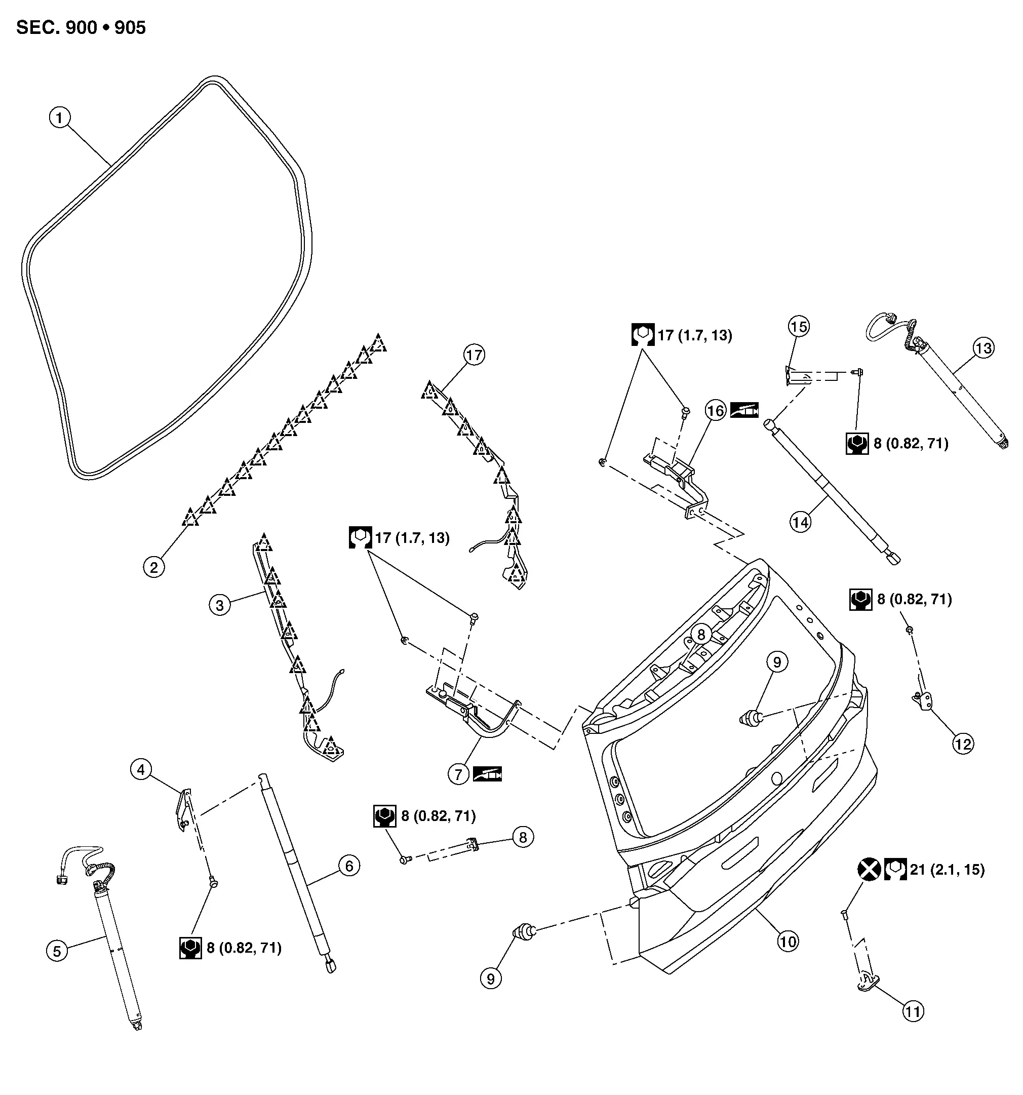
| 1. | Back door weather-strip | 2. | Roof seal | 3. | Touch sensor [LH (For automatic back door system)] |
| 4. | Back door stay/spindle unit bracket upper (LH) | 5. | Spindle unit [LH (For automatic back door system)] | 6. | Back door stay [LH (Except for automatic back door system)] |
| 7. | Back door hinge (LH) | 8. | Back door stay/spindle unit bracket (LH) lower | 9. | Back door bumper |
| 10. | Back door | 11. | Back door striker | 12. | Back door stay/spindle unit bracket (RH) lower |
| 13. | Spindle unit [RH (For automatic back door system)] | 14. | Back door stay [RH (Except for automatic back door system)] | 15. | Back door stay/spindle unit bracket (RH) upper |
| 16. | Back door hinge (RH) | 17. | Touch sensor [RH (For automatic back door system)]] |
 |
: Clip |
Back Door Assembly Nissan Pathfinder SUV
Removal and Installation
CAUTION:
-
Use two people when removing or installing back door due to its heavy weight.
-
Use shop cloths to protect surrounding components from damage during removal and installation of back door.
REMOVAL
Remove back door side finisher. Refer to Removal and Installation.
Disconnect all harness connectors from back door.
Remove all harness clips from back door assembly.
Remove back door harness grommet then pull harness from back door.
Disconnect washer tube.
Remove washer tube grommet and washer tube from back door.
Support back door assembly using a suitable tool.
WARNING:
Bodily injury may occur if back door assembly is not supported with a proper material when removing back door assembly.
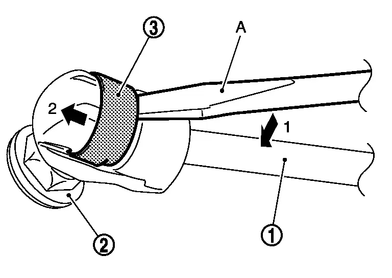
For models with automatic back door system, remove metal clip (B) between spindle unit (1) and back door stay bracket lower using a suitable tool (A) as shown.

For models without automatic back door system, remove metal clip (3) between back door stay (1) and stud ball (2) using a suitable tool (A) as shown.
Remove back door hinge bolts (back door side), and remove back door assembly.
INSTALLATION
Note the following items, and then install in the reverse order of removal.
CAUTION:
-
Apply anticorrosive agent onto the surface between hinge and door side.
-
After installation, perform the fitting adjustment. Refer to Adjustment.
-
After installation, check whether harness is not pinched. If harness is pinched, pull harness downward lightly.
-
After installation, perform "CALIBRATING CAMERA IMAGE (INTELLIGENT AROUND VIEW MONITOR)"
. Refer to Work Procedure. -
Perform “CALIBRATION OF AUTOMATIC BACK DOOR POSITION INFORMATION”. Refer to Description.
Adjustment
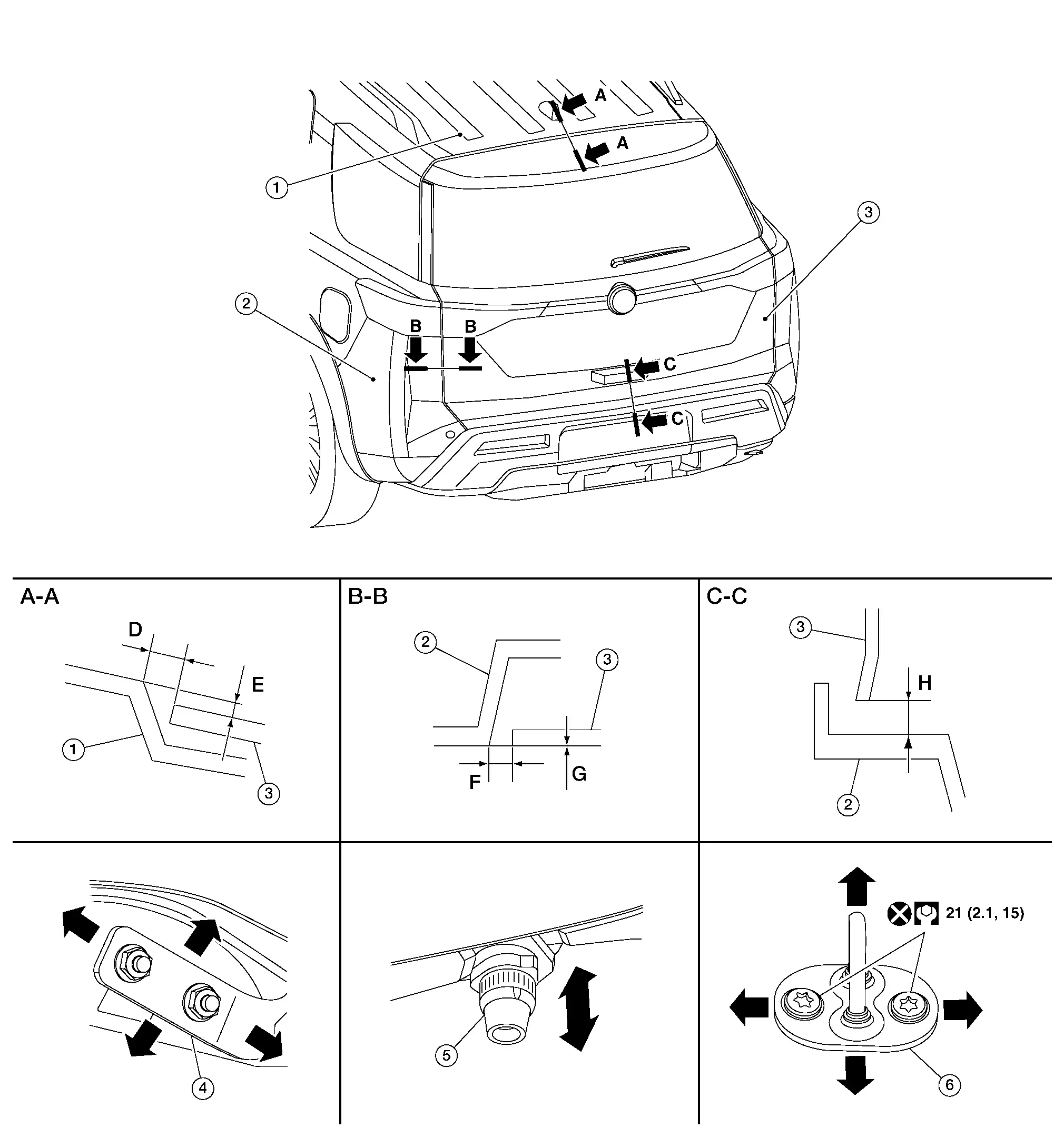
| 1. | Roof panel | 2. | Back door panel | 3. | Rear bumper fascia |
| 4. | Back door hinge | 5. | Bumper rubber | 6. | Back door striker |
Unit: mm (in)
| Portion | Standard | Difference (LH/RH MAX) | |||
|---|---|---|---|---|---|
| Roof panel – Rear spoiler | A – A | D | Clearance |
5.5 – 9.5 [0.217 – 0.374] |
≦ 2.0 [0.079] |
| E | Surface height |
(-0.5) – (+3.5) [(-0.020) – (+0.138)] |
≦ 2.3 [0.091] |
||
|
Back door panel – Rear bumper fascia |
B – B | F | Clearance |
3.0 – 7.0 [0.118 – 0.276] |
≦ 3.0 [0.118] |
| G | Surface Height |
(-1.0) – (+3.0) [(-0.165) – (+0.000)] |
≦ 3.0 [0.118] |
||
| C – C | H | Clearance |
4.9 – 9.1 [0.193 – 0.358] |
≦ 2.5 [0.098] |
|
Check the clearance and the surface height between back door and each part by seeing and touching.
If the clearance and the surface height are out of specification, adjust them according to the procedures shown below.
Fitting Adjustment Procedure
Loosen back door hinge nuts (door side).
Lift up back door approximately 100 – 150 mm (3.94 – 5.91 in) height then close it lightly and check that it is engaged firmly with back door closed.
Check clearance and surface height according to specifications provided.
Tighten back door hinge nuts to specified torque.
CAUTION:
-
After installation, check back door open/close and lock/unlock operation.
-
Check back door hinge rotating point for poor lubrication. If necessary, apply a suitable multi-purpose grease.
-
After adjusting, apply touch-up paint (body color) to heads of rear door hinge bolts and nuts.
-
Perform “CALIBRATION OF AUTOMATIC BACK DOOR POSITION INFORMATION”. Refer to Description.
Back Door Striker Nissan Pathfinder Fifth generation
Removal and Installation
REMOVAL
Remove luggage rear plate. Refer to Removal and Installation.
Remove bolts and back door striker.
INSTALLATION
Installation is in the reverse order of removal.
CAUTION:
-
Do not reuse back door striker bolts.
-
Tighten bolts to specification. Refer to Exploded View.
-
After installation, check back door open/close operation. If necessary, adjust door striker. Refer to Adjustment.
Adjustment
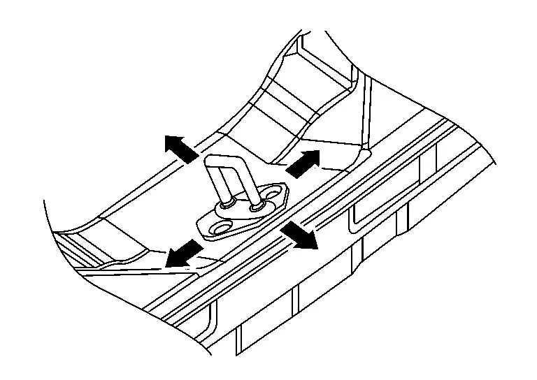
DOOR STRIKER ADJUSTMENT
Loosen door striker bolts.
Adjust door striker so that it becomes parallel with front door lock insertion direction.
CAUTION:
Perform calibration of automatic back door position information. Refer to Description.
Tighten door striker bolts to specification. Refer to Exploded View.
Back Door Hinge Nissan Pathfinder 2026
Removal and Installation
REMOVAL
Remove back door assembly. Refer to Removal and Installation.
Partially remove rear of headlining. Refer to Removal and Installation.
Remove nuts and back door hinge.
INSTALLATION
Installation is in the reverse order of removal.
CAUTION:
-
Tighten nuts to specification. Refer to Exploded View.
-
Apply anticorrosive agent onto surface between hinge and body side.
-
After installation, perform back door assembly adjustment procedure. Refer to Adjustment.
Back Door Stay Nissan Pathfinder 5th Gen
Removal and Installation
REMOVAL
CAUTION:
2 workers are required to support back door.
Support the back door with the suitable material to prevent it from falling.
WARNING:
Bodily injury may occur if no supporting rod is holding the back door open when removing the back door stay.
Remove metal clip (3) between back door stay (1) and stud ball (2) using a suitable tool (A) as shown.

CAUTION:
2 workers are required to support back door.
Separate back door stay from stud ball on back door side.
Remove back door stay mounting bolts, and then remove back door stay.
INSTALLATION
Installation is in the reverse order of removal.
Spindle Unit Nissan Pathfinder 2022
Removal and Installation
REMOVAL
Support back door using a suitable tool.
WARNING:
Bodily injury may occur if back door is not supported properly when removing back door spindle unit.
Remove luggage side upper finisher. Refer to Removal and Installation.
Disconnect the harness connector (A) from spindle unit (LH).
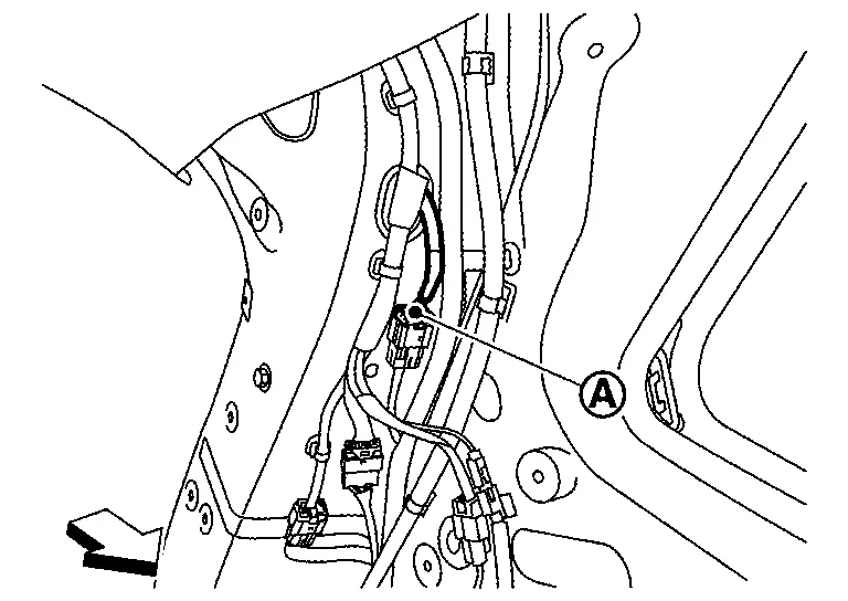
 |
: Nissan Pathfinder Vehicle front |
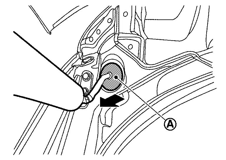
Remove spindle unit harness grommet (A) from back pillar in direction shown.
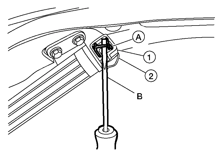
Remove metal clip (A) from spindle unit upper hinge ball socket (1) using a suitable tool (B) and release spindle unit from spindle unit upper hinge (2).
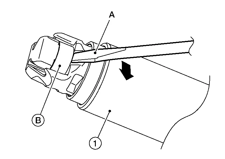
Remove metal clip (B) between spindle unit (1) and back door stay bracket lower using a suitable tool (A) as shown.
Pull harness through Nissan Pathfinder vehicle body and remove spindle unit.
INSTALLATION
Note the following items, and then install in the reverse order of removal.
CAUTION:
-
When reusing stud ball, always apply locking sealant before installing stud ball to back door.
-
After installation, check back door open/close and lock/unlock procedure.
-
Perform “CALIBRATION OF AUTOMATIC BACK DOOR POSITION INFORMATION”. Refer to Description.
 NOTE:
NOTE:
Check spindle unit grommet lubrication condition. If necessary, apply a suitable lubrication to spindle unit grommet during installation.
Back Door Weather-Strip Nissan Pathfinder SUV
Removal and Installation
REMOVAL
Carefully remove back door weather-strip from opening door joint.
INSTALLATION
Beginning with upper section, align weather-strip mark with vehicle center position mark and install weather-strip to Nissan Pathfinder vehicle.
For lower section, align weather-strip seam with center of back door striker.
 NOTE:
NOTE:
Pull weather-strip gently to ensure that there are no loose sections.

Nissan Pathfinder (R53) 2022-2026 Service Manual
Back Door
Contact Us
Nissan Pathfinder Info Center
Email: info@nipathfinder.com
Phone: +1 (800) 123-4567
Address: 123 Pathfinder Blvd, Nashville, TN 37214, USA
Working Hours: Mon–Fri, 9:00 AM – 5:00 PM (EST)
