Nissan Pathfinder: Audio, Visual & Navigation System - System Description
Component Parts Nissan Pathfinder 2022
Rear View Monitor System
Component Parts Location
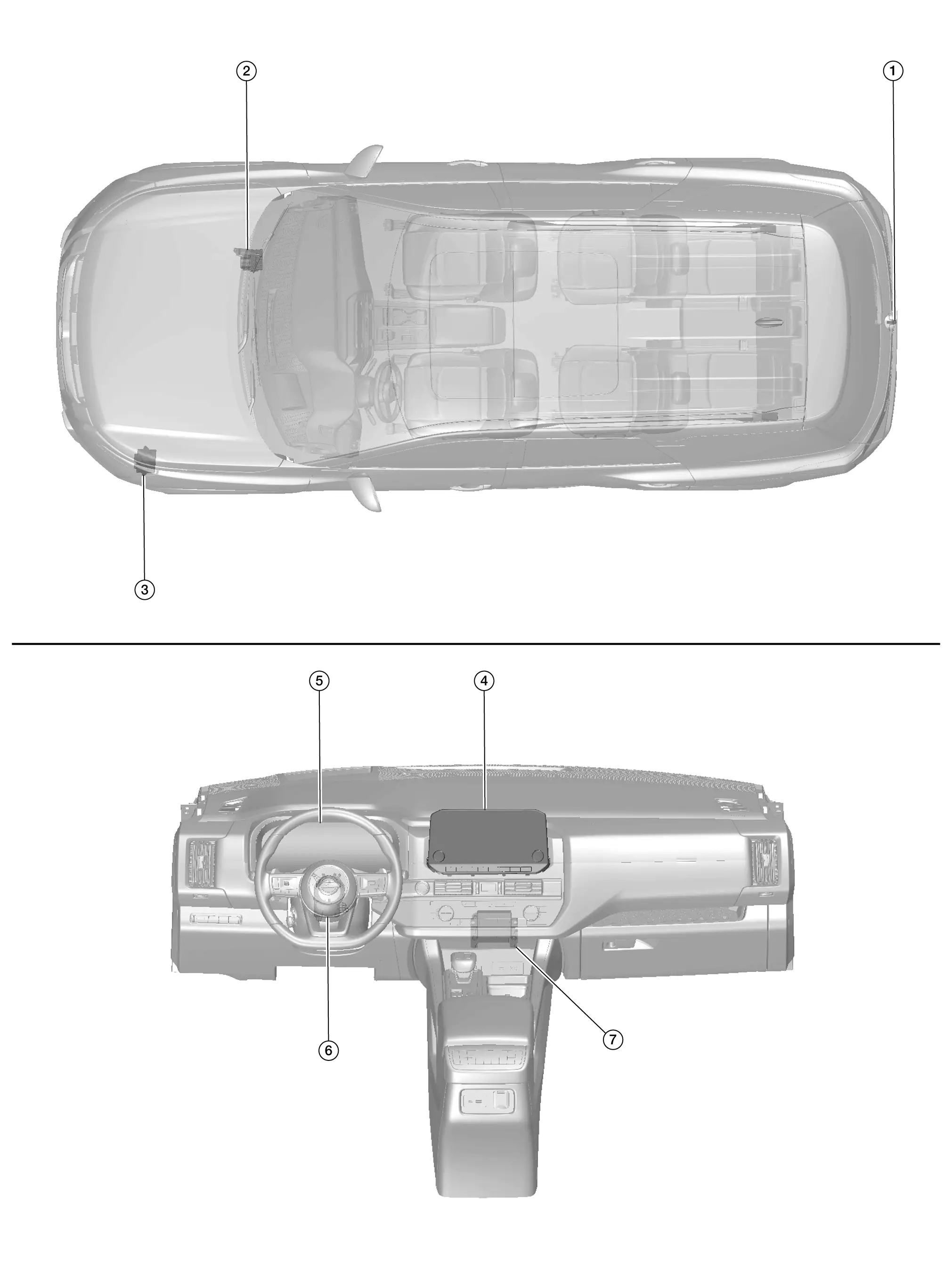
| No. | Component | Function |
|---|---|---|
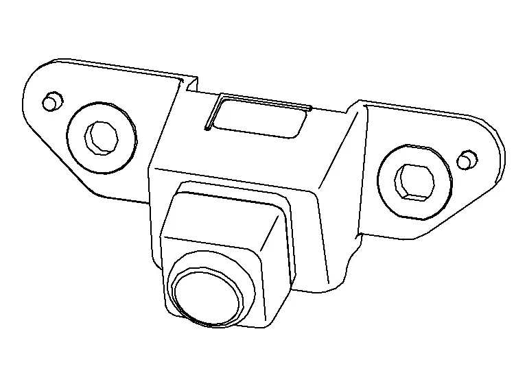
| 1. | Rear view camera | Refer to Rear View Camera. |
| 2. | ABS (Anti-lock Braking System) actuator and electric unit (control unit) | Provides AV control unit with the wheel speed signals via CAN communication. |
| 3. | TCM (Transmission Control Module) | Provides AV control unit with the shift position signal via CAN communication. |
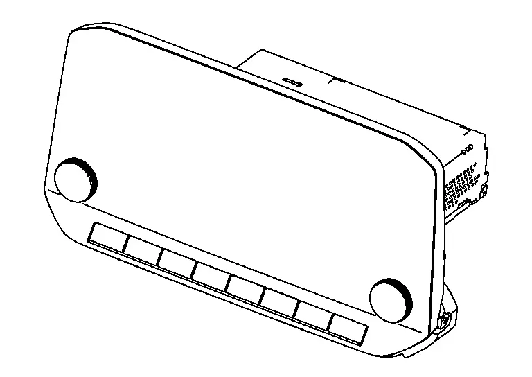
| 4. | AV control unit | Refer to AV Control Unit. |
| 5. | Combination meter |
Provides AV control unit with the steering switch signals via AV communication. Provides AV control unit with the following signals via CAN communication:
|
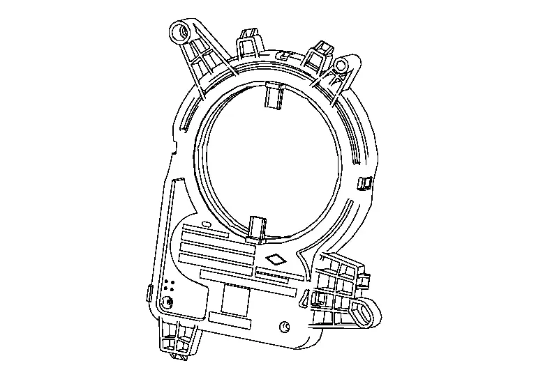
| 6. | Steering angle sensor | Refer to Steering Angle Sensor. |
| 7. | Sonar control unit | Provides AV control unit with the sonar detection display request signal via CAN communication. |
AV Control Unit
-
An 8-inch color display with multi-touch control, an AM/FM electronic tuner radio with RDS and camera controller are integrated into the AV Control unit.
-
The color display is a high resolution monitor that includes touch panel functions.
Rear View Camera
-
The rear view camera is installed at the center of the back door finisher.
-
Power for the camera is supplied from the AV control unit, and the image at the rear of the Nissan Pathfinder vehicle is sent to the AV control unit display.
Steering Angle Sensor
-
Steering angle sensor is installed to the combination switch (spiral cable).
-
Steering angle sends the steering angle signal necessary for predictive course line of the rear view monitor to the AV control unit via CAN communication.
System Nissan Pathfinder R53
System Description
SYSTEM DIAGRAM
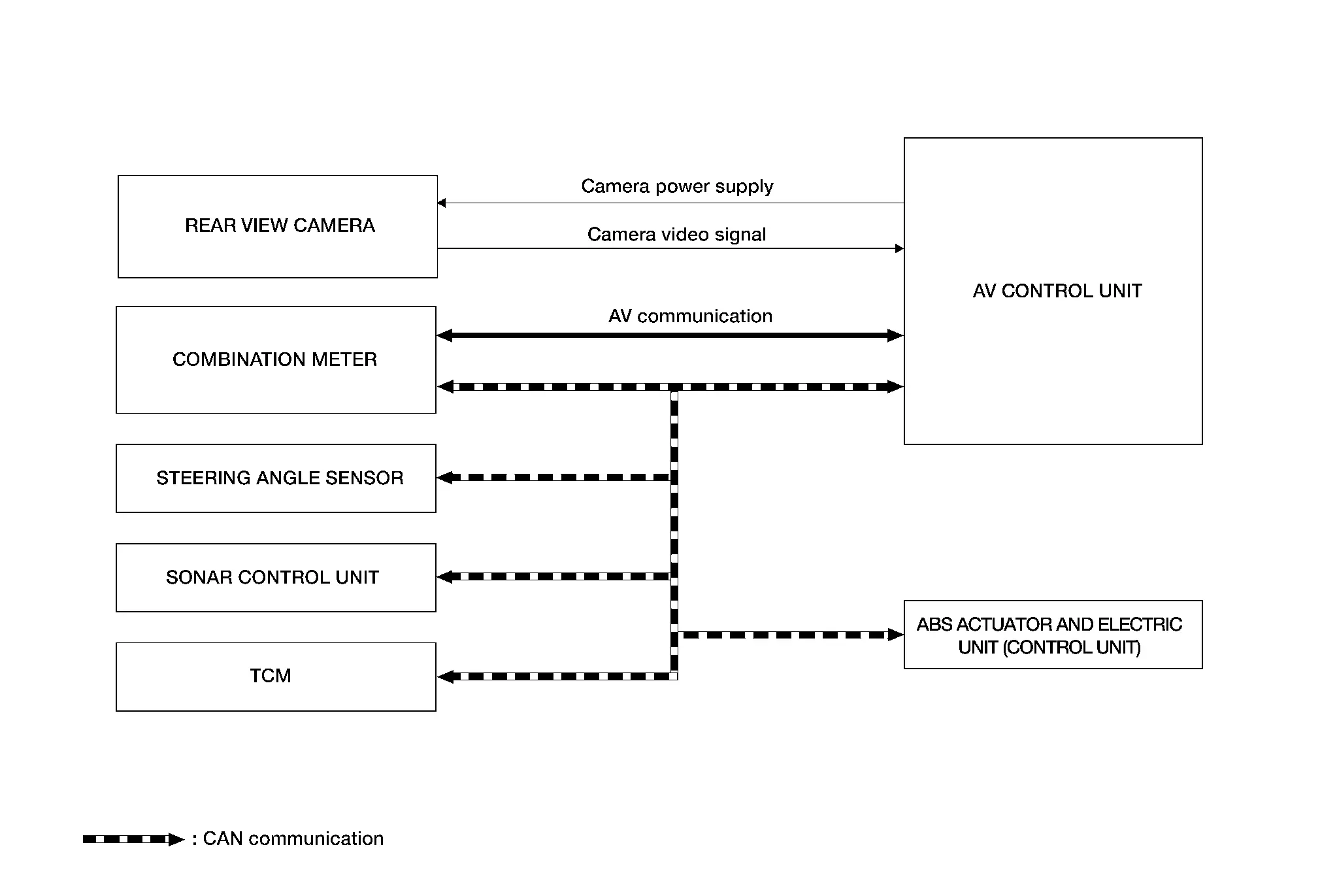
AV Control Unit Input Signal (CAN Communication)
| Transmit unit | Signal name |
|---|---|
| ABS actuator and electric unit (control unit) | Wheel speed signals |
| Combination meter |
|
| Sonar control unit | Sonar detection display request signal |
| Steering angle sensor | Steering angle signal |
| TCM | Shift position signal |
DESCRIPTION
Operation Description
-
When the selector lever is shifted to the reverse position, the rear view monitor image is displayed.
-
When the selector lever is shifted to any position other than the reverse position, the original image (the image displayed before the rear view monitor image) is displayed.
-
The sonar indicator is displayed on display (superimposed on the camera image) in combination with the camera assistance sonar system to warn of the approach of an obstacle.
-
Camera image is displayed on the display when an obstacle is detected by sonar system.
Camera Image Operation Principle
-
The AV control unit receives the reverse signal input and supplies power to the rear view camera.
-
The rear view camera supplies the image signal to the AV control unit.
-
The AV control unit displays the rear view camera image when the reverse signal is received.
-
The AV control unit generates the warning message, Nissan Pathfinder vehicle width guide lines and the predicted course lines on the image from the rear view camera.
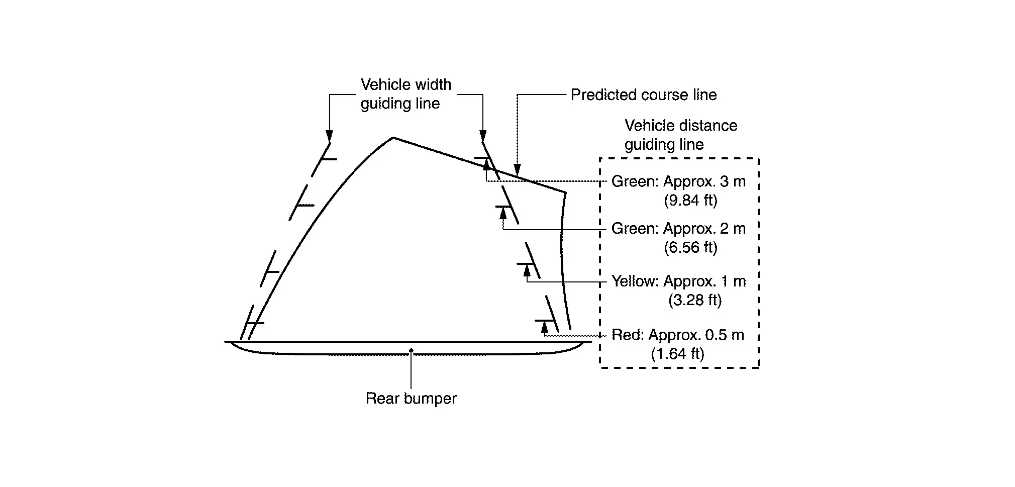
Vehicle Width Guide Lines and Predicted Course Lines Display Function
-
The vehicle width guide lines and the predicted course lines that indicate the vehicle route according to the steering angle are displayed to allow the driver to more easily judge distances between the Nissan Pathfinder vehicle and objects and to help the driver back into a parking space.
-
The AV control unit receives the steering signal from the steering sensor via CAN communication and draws a Nissan Pathfinder vehicle width guide line according to the steering angle.
-
Vehicle width guide lines are displayed translucently.
-
The predicted course lines are not displayed when the steering is in the neutral position.
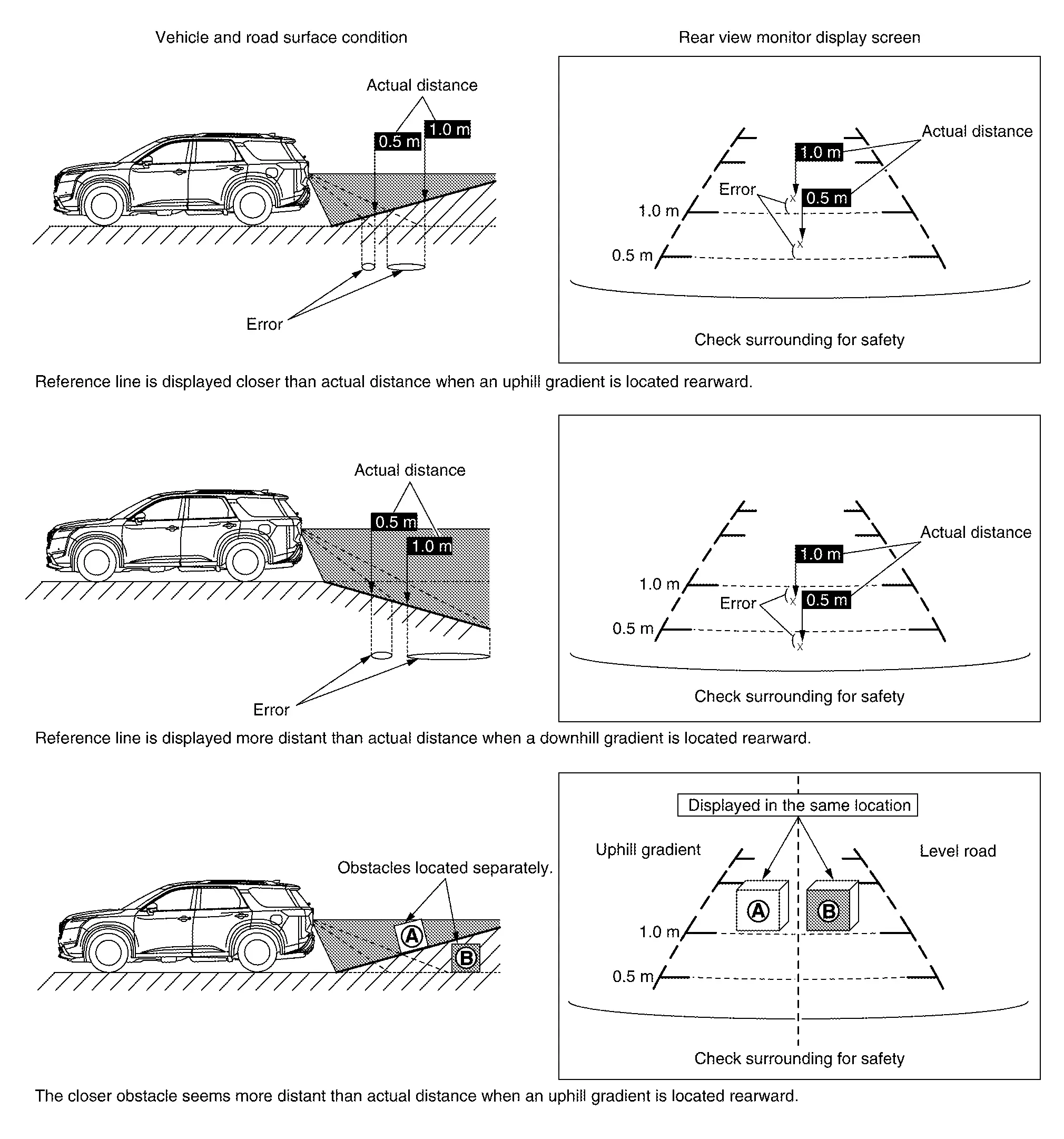
Precautions for Vehicle Width Guide Lines and Predicted Course Lines
Vehicle width guide lines and predicted course lines displayed may be different from actual lines depending on Nissan Pathfinder vehicle conditions and road conditions.
Precautions for road conditions
-
Since vehicle width guide lines and predicted course lines are drawn based on the road, a different distance may be displayed if uphill or downhill gradient is present nearby.
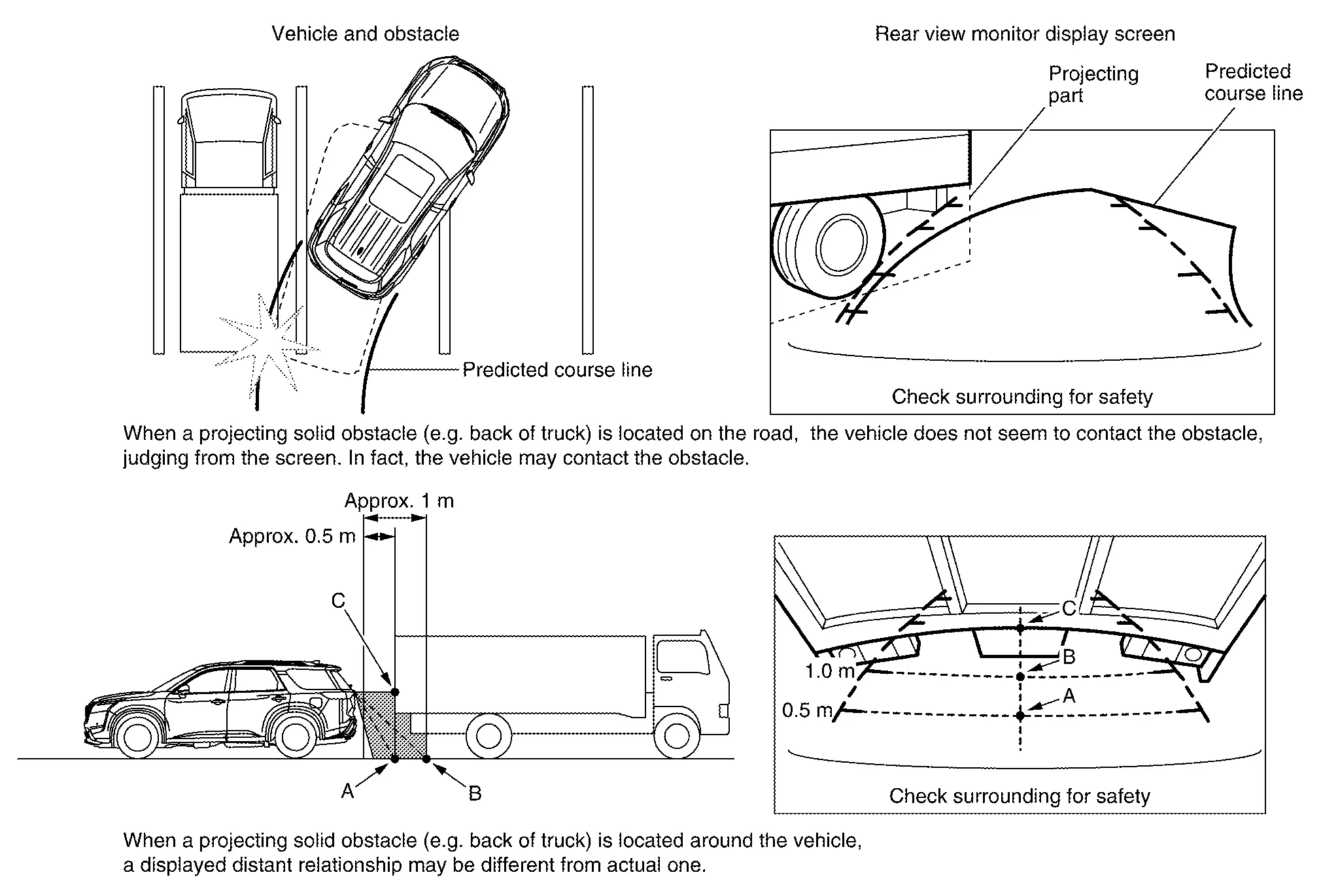
Precautions for block
-
Since vehicle width guide lines and predicted course lines are drawn based on the road, a different distance may be displayed if a projecting obstacle is present nearby.
CAMERA ASSISTANCE SONAR FUNCTION
-
Sonar sensors are installed on front and rear bumpers. When an obstacle is detected while rear camera is displayed, a sonar indicator display and buzzer sound notify the driver of the proximity of an obstacle. When an obstacle is detected while rear view camera is not displayed, rear view camera screen is displayed automatically, and then notification is similar as while rear view camera is displayed.
-
Approaching distance between bumper and obstacle is displayed in 3 stages according to the color of the sonar indicator in display and blinking cycle of indicator.
-
Warning by buzzer sound notifies distance to obstacle according to a 3-stage cycle.
Diagnosis System (av Control Unit) Nissan Pathfinder SUV
Description
Refer to Description.
On Board Diagnosis Function
Refer to On Board Diagnosis Function.
CONSULT Function
Refer to CONSULT Function.

Nissan Pathfinder (R53) 2022-2026 Service Manual
System Description
Contact Us
Nissan Pathfinder Info Center
Email: info@nipathfinder.com
Phone: +1 (800) 123-4567
Address: 123 Pathfinder Blvd, Nashville, TN 37214, USA
Working Hours: Mon–Fri, 9:00 AM – 5:00 PM (EST)
