Nissan Pathfinder: Driveline - Unit Disassembly and Assembly
Electro-Hydraulic Coupling Nissan Pathfinder 5th Gen
Exploded View
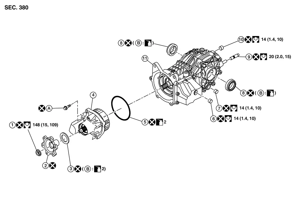
| 1. | Companion flange lock nut | 2. | Companion flange | 3. | Electro-hydraulic coupling oil seal |
| 4. | Electro-hydraulic coupling assembly | 5. | O-ring | 6. | Filler plug |
| 7. | Drain plug | 8. | Side oil seal | 9. | Stud |
| 10. | Filler plug | 11. | Final drive assembly | A. | Refer to Removal and Installation. |
| B. | Oil seal lip |
Disassembly
DISASSEMBLY
 NOTE:
NOTE:
Before replacing electro-hydraulic coupling due to vibration and/or noise when making low speed turns, refer to TSB to assist in proper diagnosis.
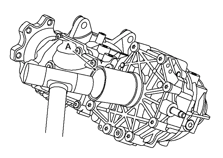
Remove electro-hydraulic coupling assembly bolts (A) and remove electro-hydraulic coupling assembly (1) from final drive assembly (2).
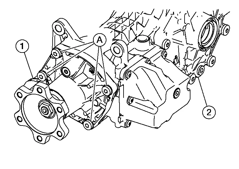
CAUTION:
Oil is drained from between electro-hydraulic coupling assembly and final drive assembly. When removing, set a pan under them.
Remove O-ring (1) from electro-hydraulic coupling assembly.
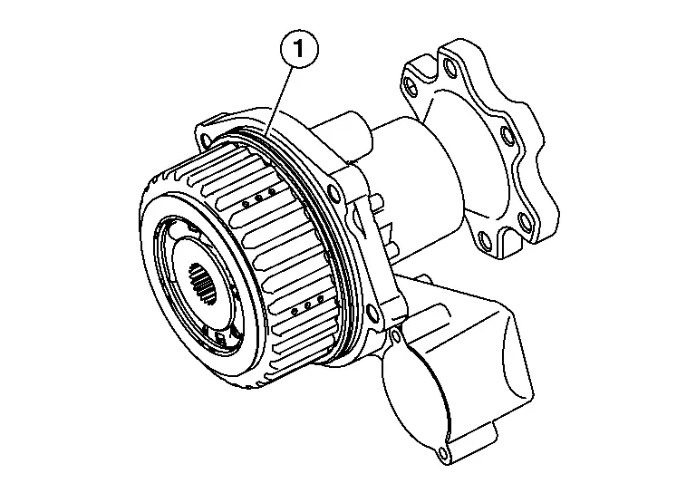
CAUTION:
-
Do not use a tool.
-
Do not damage electro-hydraulic coupling assembly.
Loosen companion flange lock nut (1) and remove it.
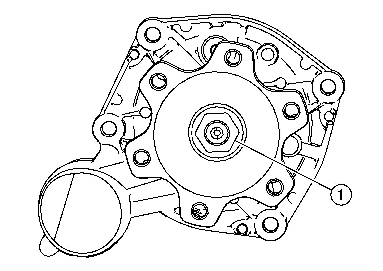
CAUTION:
Do not reuse companion flange lock nut.
Remove companion flange.
CAUTION:
Do not reuse companion flange.
Remove electro-hydraulic coupling oil seal (1) using oil seal remover [commercial service tool (A)].
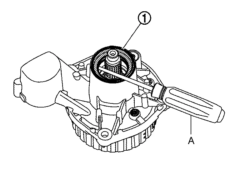
CAUTION:
Do not damage electro-hydraulic coupling assembly.
Perform inspection after disassembly. Refer to Inspection.
Assembly
ASSEMBLY
CAUTION:
Do not allow contaminants to adhere to drum surface or the mating surface of companion flange. Contaminants can cause damage to electro-hydraulic coupling.
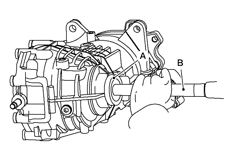
Using the drift [commercial service tool (A)], install electro-hydraulic coupling oil seal (1) as shown in the figure.
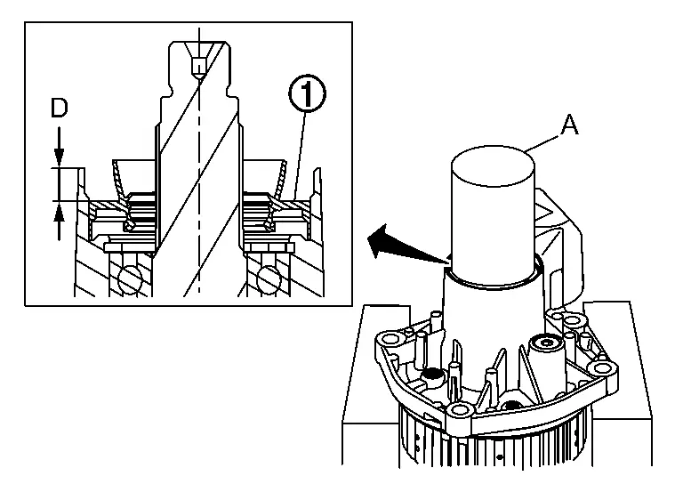
| Installation dimension | |
| D | : 7.15 ±0.1 mm (0.2815 ±0.004 in) |
CAUTION:
-
Do not reuse oil seal.
-
When installing, never incline oil seal.
-
Check that the oil seal lip is filled up with grease.
-
Apply electro-hydraulic coupling oil lightly and evenly onto the outer circumference of oil seal.
Install companion flange.
CAUTION:
Do not reuse companion flange.
Tighten companion flange lock nut (1) to the specified torque.

-
For tightening torque, refer to Exploded View.
CAUTION:
Do not reuse companion flange lock nut.
Install O-ring (1) to electro-hydraulic coupling assembly.

CAUTION:
-
Do not reuse O-ring.
-
Apply electro-hydraulic coupling oil lightly and evenly onto O-ring.
-
When installing O-ring, do not use a tool.
-
Do not damage O-ring.
Tighten electro-hydraulic coupling assembly bolts to the specified torque diagonally.

-
For tightening torque, refer to Exploded View.
Inspection
INSPECTION AFTER DISASSEMBLY
Bearing
-
If unusual noise from the bearing is observed, replace electro-hydraulic coupling assembly.
Oil Seal
-
Whenever disassembled, replace.
-
If wear, deterioration of adherence (sealing force lips), or damage is detected on the lips, replace them.
Companion Flange
-
Whenever disassembled, replace.
-
If any chipped mark [about 0.1 mm, (0.004 in)] or other damage on the contact sides of the lips of the companion flange is found, replace.
Differential Assembly Nissan Pathfinder 2026
Exploded View

| 1. | Companion flange lock nut | 2. | Companion flange | 3. | Electro-hydraulic coupling oil seal |
| 4. | Electro-hydraulic coupling assembly | 5. | O-ring | 6. | Filler plug |
| 7. | Drain plug | 8. | Side oil seal | 9. | Stud |
| 10. | Filler plug | 11. | Final drive assembly | A. | Refer to Removal and Installation. |
| B. | Oil seal lip |
Disassembly
DISASSEMBLY
 NOTE:
NOTE:
Before replacing, servicing, or repairing rear final drive assembly due to vibration and/or noise when making low speed turns, refer to TSB to assist in proper diagnosis.
Remove drain plug and drain gear oil. Refer to Exploded View.
CAUTION:
Do not reuse gear oil.
Remove filler plug from final drive assembly. Refer to Exploded View.
Remove the side oil seal (1), using oil seal remover (commercial service tool).
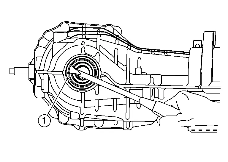
CAUTION:
Do not damage gear carrier and rear cover.
Remove stud bolt from final drive assembly. Refer to Exploded View.
 NOTE:
NOTE:
It is not necessary to remove stud bolt except when it is replaced.
Perform inspection after disassembly. Refer to Inspection.
Assembly
ASSEMBLY
Install stud bolt to final drive assembly.
-
For tightening torque, refer to Exploded View.
CAUTION:
-
Screw the stud bolt until the flange surface is fully seated.
-
Do not reuse stud bolt.
Install side oil seal (cover side) until it becomes flush with the carrier end, using the drift (A) [SST: KV40105740 ( — )].
CAUTION:
-
Do not reuse oil seal.
-
When installing, install seal evenly.
-
Apply multi-purpose grease onto oil seal lips, and gear oil onto the circumference of the oil seal.
Install side oil seal (carrier side) until it becomes flush with the carrier end, using the drift (A) and drift bar (B).
| A | : Drift [SST: KV31103000 (NI-38982)] |
| B | : Drift bar [SST: ST35325000 ( — )] |
CAUTION:
-
Do not reuse oil seal.
-
When installing, install seal evenly.
-
Apply multi-purpose grease onto oil seal lips, and gear oil onto the circumference of the oil seal.
Install drain plug to final drive assembly. Refer to Exploded View.
CAUTION:
Do not reuse drain plug.
Install filler plug to final drive assembly. Refer to Exploded View.
CAUTION:
Do not reuse filler plug.
Inspection
INSPECTION AFTER DISASSEMBLY
Oil Seal
-
Whenever disassembled, replace.
-
If wear, deterioration of adherence (sealing force lips), or damage is detected on the lips, replace them.

Nissan Pathfinder (R53) 2022-2026 Service Manual
Unit Disassembly and Assembly
Contact Us
Nissan Pathfinder Info Center
Email: info@nipathfinder.com
Phone: +1 (800) 123-4567
Address: 123 Pathfinder Blvd, Nashville, TN 37214, USA
Working Hours: Mon–Fri, 9:00 AM – 5:00 PM (EST)
