Nissan Pathfinder: Driveline - Removal and Installation
Side Oil Seal Nissan Pathfinder 5th Gen
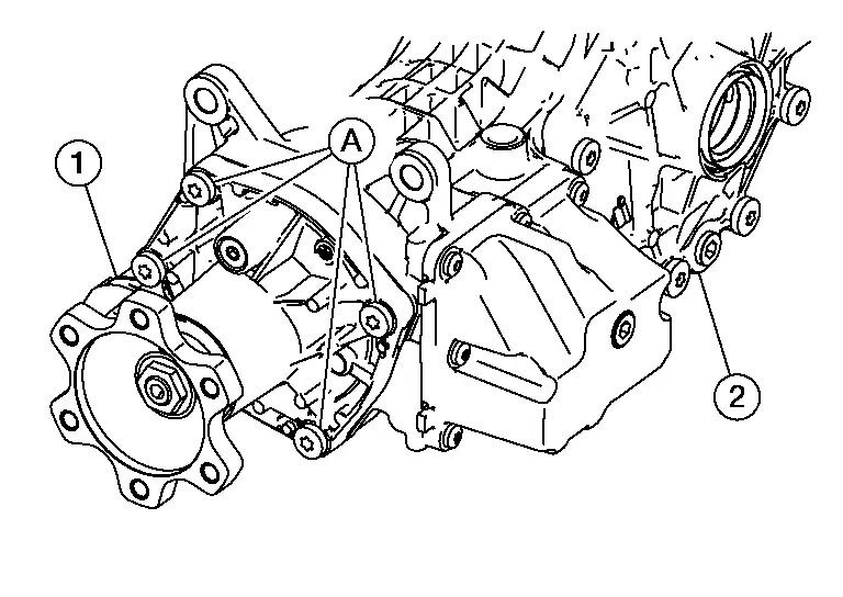
Exploded View
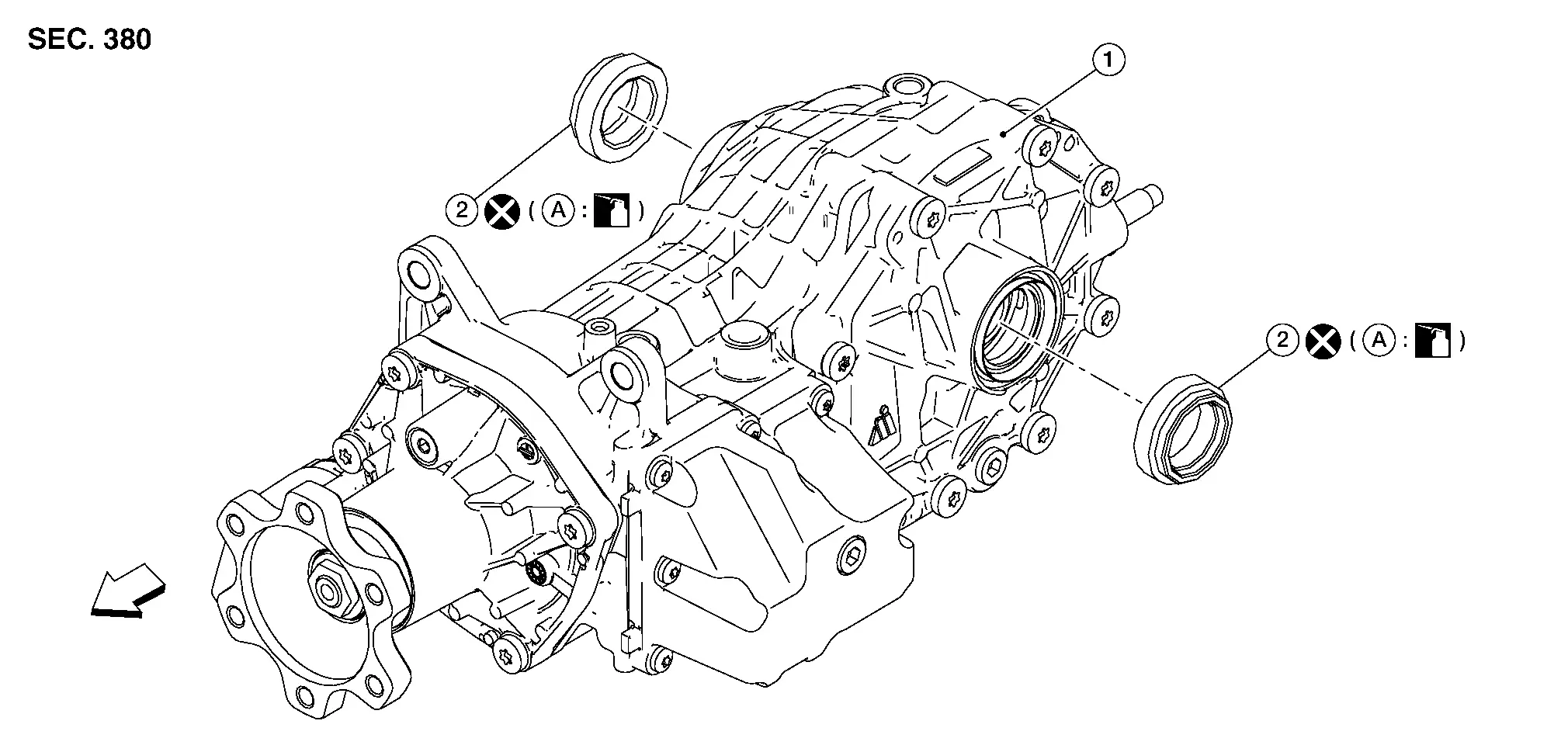
| 1. | Final drive assembly | 2. | Side oil seal |
| A. | Oil seal lip |
 |
Nissan Pathfinder Vehicle front |
Removal and Installation
REMOVAL
Remove rear drive shaft (LH) or (RH) as necessary. Refer to Removal and Installation.
Remove side oil seal (1), using a suitable tool.
CAUTION:
-
Do not reuse seal.
-
Be careful not to damage gear carrier and side cover.
INSTALLATION
Install side oil seal (cover side) until it becomes flush with the carrier end, using Tool (A).
| Tool number (A) | : KV40105740 ( — ) |
CAUTION:
-
Do not reuse side oil seal.
-
When installing, do not incline side oil seals.
-
Apply rear differential gear oil onto side oil seal lip.
Install side oil seal (carrier side) until it becomes flush with the carrier end, using Tool (A) and Tool (B).
| Tool number (A) | : ST35325000 ( — ) |
| Tool number (B) | : KV31103000 (NI-38982) |
CAUTION:
-
Do not reuse side oil seal.
-
When installing, do not incline side oil seals.
-
Apply rear differential gear oil onto side oil seal lip.
Install rear drive shaft (LH) or (RH) as necessary. Refer to Removal and Installation.
Check rear differential gear oil level and check for rear differential gear oil leaks. Refer to Inspection.
Air Breather Nissan Pathfinder 2026
Exploded View
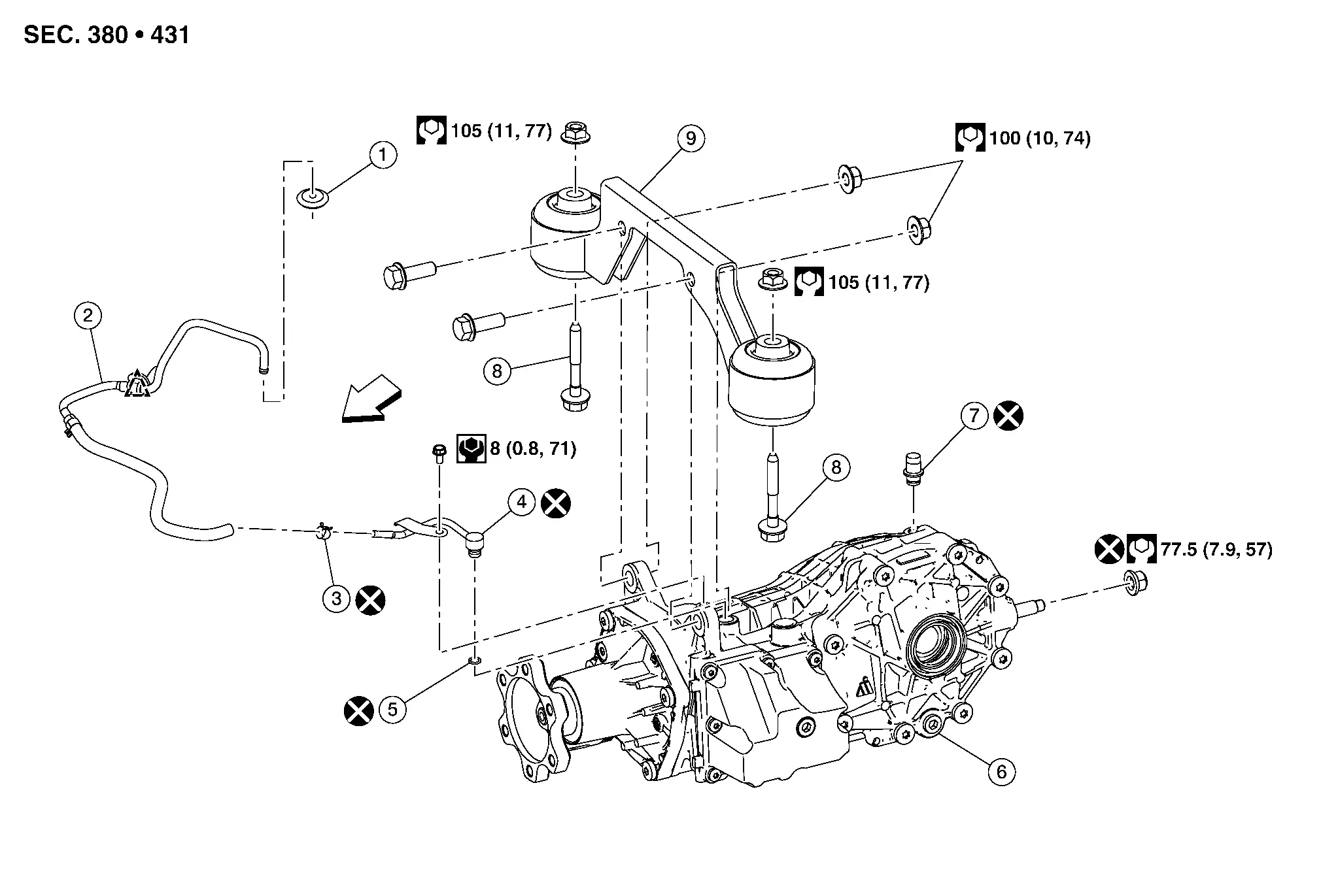
| 1. | Plug | 2. | Breather hose | 3. | Hose clamp |
| 4. | Breather tube | 5. | O-ring | 6. | Final drive assembly |
| 7. | Breather | 8. | Bolt | 9. | Final drive assembly bracket |
 |
Clip |
 |
Front |
Removal and Installation
REMOVAL
Final Drive Side
Remove breather assembly from rear final drive assembly.
-
When removing/installing breather assembly, remove rear final drive assembly from the vehicle. Refer to Removal and Installation.
Electro-hydraulic Coupling Side
Remove rear final drive assembly. Refer to Removal and Installation.
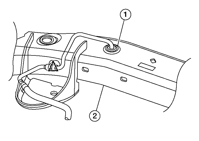
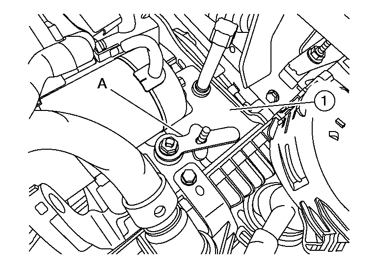
Remove plug (1) from rear suspension member (2).

 |
: Clip |
Remove clip from rear suspension member (2) and remove breather hose assembly.
Remove breather tube bolt and remove air breather tube.
INSTALLATION
Note the following, and install in the reverse order of removal.
-
For non-reusable parts, refer to Exploded View.
-
When installing breather hose, make sure there are no pinched or restricted areas on breather hose caused by bending or winding.
Final Drive Side
-
Breather assembly must be press fitted until whole circumference of flange (A) reach the surface (B) of rear cover.
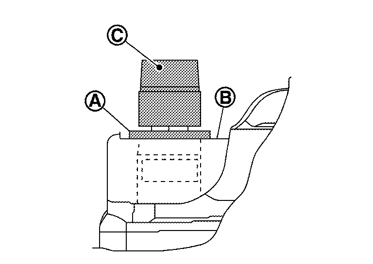
CAUTION:
Do not press the cap (C).
Electro-hydraulic Coupling Side
-
When installing coupling breather tube, make sure there is no damage on O-ring.
 NOTE:
NOTE:
In case of difficult insertion, apply electro-hydraulic coupling oil (genuine part) to O-ring.
-
Securely install plug (1) to suspension member (2) and install clip.

: Clip -
*Refer to the following when installing water hose.
Breather hose (1) Installation side tube (2) Direction of paint mark Hose insertion depth Breather hose Breather tube Upward End reaches the 2-stage bulge. 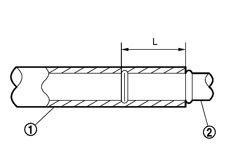
-
*Refer to the following when installing hose clamps.
Breather hose (1) Installation side tube (2) Hose clamp (3) Direction of tab Clamping position* Breather hose A Breather tube Upward and 45° rightward A: 5-7 mm (0.20 - 0.28 in) (L) from hose end. 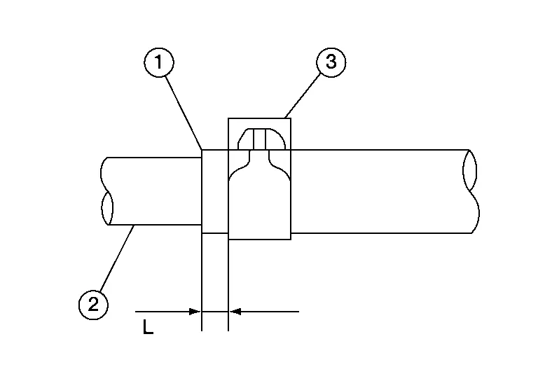
Electro-Hydraulic Coupling Nissan Pathfinder
Removal and Installation
CAUTION:
When replacing electro-hydraulic coupling, be sure to perform "ADDITIONAL SERVICE WHEN REPLACING ELECTRO-HYDRAULIC COUPLING". Refer to Description.
 NOTE:
NOTE:
Before replacing electro-hydraulic coupling due to vibration and/or noise when making low speed turns, refer to TSB to assist in proper diagnosis.
REMOVAL
Remove air duct hose and resonator assembly. Refer to Exploded View.
Use Tool (A) to place transaxle assembly (1) in neutral position.
| Tool (A) | : — (NI-53123) |
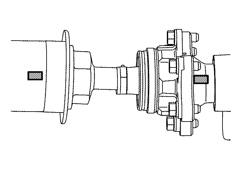
Put matching marks onto propeller shaft flange yokes or electro-hydraulic coupling companion flange.
CAUTION:
For matching marks, use paint. Do not damage propeller shaft flange yokes or electro-hyrdaulic coupling companion flange.
Remove propeller shaft assembly bolts from the rear final drive assembly side. Refer to Exploded View.
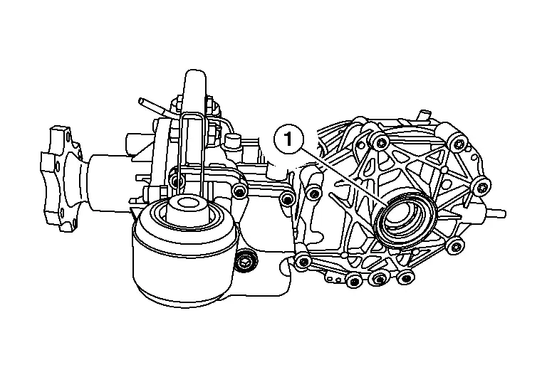
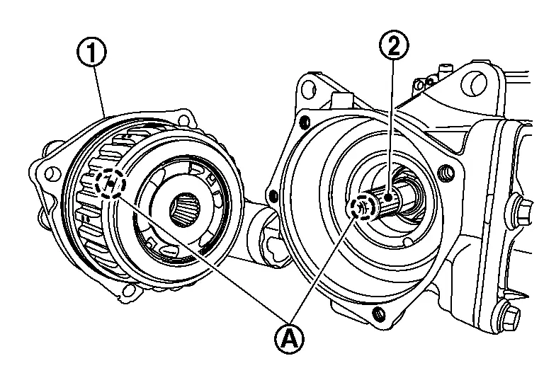
Remove electro-hydraulic coupling bolts (A) and remove electro-hyrdaulic coupling (1) from final drive assembly (2).

CAUTION:
Oil is drained from between electro-hydraulic coupling assembly and final drive assembly. When removing, set a pan under them.
Remove electro-hydraulic coupling assembly.
INSTALLATION
Installation is in the reverse order of removal.
CAUTION:
When replacing electro-hydraulic coupling, be sure to perform "ADDITIONAL SERVICE WHEN REPLACING ELECTRO-HYDRAULIC COUPLING". Refer to Description.
-
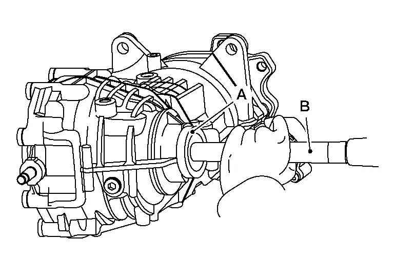
Match electro-hydraulic coupling assembly to spline of drive pinion, then install it to final drive assembly.
CAUTION:
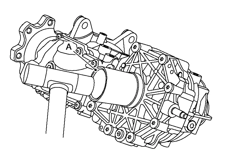
Aligning marking (A) on drum of electro-hydraulic coupling assembly (1) and marking (A) on tip of drive pinion (2).
-
When installing the electro-hydraulic coupling assembly, install the bolts to the standard below, tighten bolts to the specified torque and then tighten to the specified angle.
Transfer assembly bolts Step 1 : 20 N·m (2 kg-m, 15 ft-lb) Step 2 : Tighten 85° - 95° -
Fill with electro-hydraulic coupling oil after installing final drive assembly to the Nissan Pathfinder vehicle. Refer to Adjustment.
CAUTION:
Do not reuse electro-hydraulic coupling oil.
-
Align matching marks to install propeller shaft assembly to final drive and transfer companion flanges.
-
Perform inspection after installation. Refer to Inspection.
-
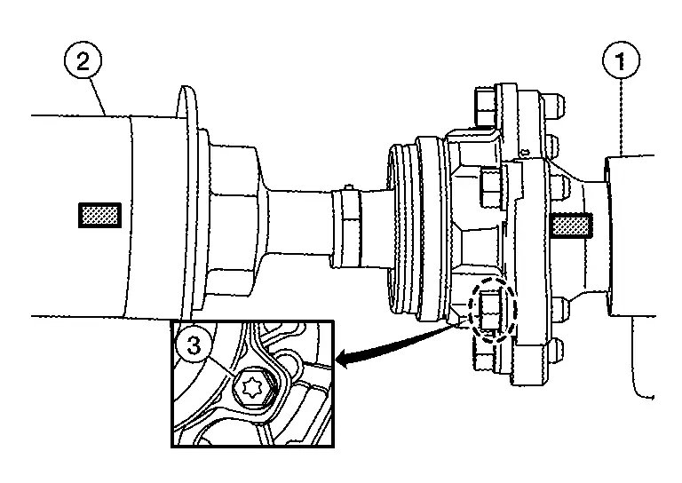
After tightening the bolts and nuts to the specified torque, check that the bolts (3) on the flange side are tightened as shown.
-
Final drive assembly (1)
-
Propeller shaft assembly (2)
-
-
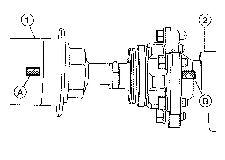
If propeller shaft assembly or final drive assembly has been replaced, connect them as follows:
-
Install propeller shaft (1) while aligning its matching mark (A) with the matching mark (B) of the final drive (2) on the joint as close as possible.
-
Tighten bolts and nuts of propeller shaft and final drive to the specified torque.
-
Adjustment
ADJUSTMENT
Electro-Hydraulic Coupling Oil Filling, Air Bleeding and Initialize Oil Deterioration Level
When the electro-hydraulic coupling oil is drained, such as when replacing or removing/installing electro-hydraulic coupling component parts, the air bleeding and initialize oil deterioration level of electro-hydraulic coupling oil is required after fill with new electro-hydraulic coupling oil.
Fill with electro-hydraulic coupling oil following the instructions below.
Remove filler plug from coupling oil tank cover.
Fill with new electro-hydraulic coupling oil to specified amount.
| Specified amount | : Refer to General Specification. |
CAUTION:
-
Use LSC Transmission Fluid 12-301 or equivalent for electro-hydraulic coupling oil.
-
When using oil, allow the additives to diffuse well before use.
-
Oil that has been stored for 12 months can not be used.
 NOTE:
NOTE:
-
Oil level should be level with bottom of filler plug mounting hole.
-
This fluid has a tendency to have clutch additive separate during long storage, it is critical to shake the fluid for 30–60 seconds before using.
Install filler plug to coupling oil tank cover.
CAUTION:
Do not reuse gasket.
Tighten filler plug to the specified torque. Refer to Exploded View.
Perform air bleeding and initialize oil deterioration level of electro-hydraulic coupling oil. Refer to Description.
Check oil level for electro-hydraulic coupling oil again.
 NOTE:
NOTE:
The oil level may be reduced after air bleeding.
Check oil level from filler plug mounting hole.CAUTION:
Place the ignition switch in OFF position while checking oil level.
-
Oil level should be level with bottom of filler plug mounting hole. Add electro-hydraulic coupling oil if necessary.

Nissan Pathfinder (R53) 2022-2026 Service Manual
Removal and Installation
Contact Us
Nissan Pathfinder Info Center
Email: info@nipathfinder.com
Phone: +1 (800) 123-4567
Address: 123 Pathfinder Blvd, Nashville, TN 37214, USA
Working Hours: Mon–Fri, 9:00 AM – 5:00 PM (EST)
