Nissan Pathfinder: Maintenance - Engine Maintenance
Drive Belt Nissan Pathfinder Fifth generation
Exploded View
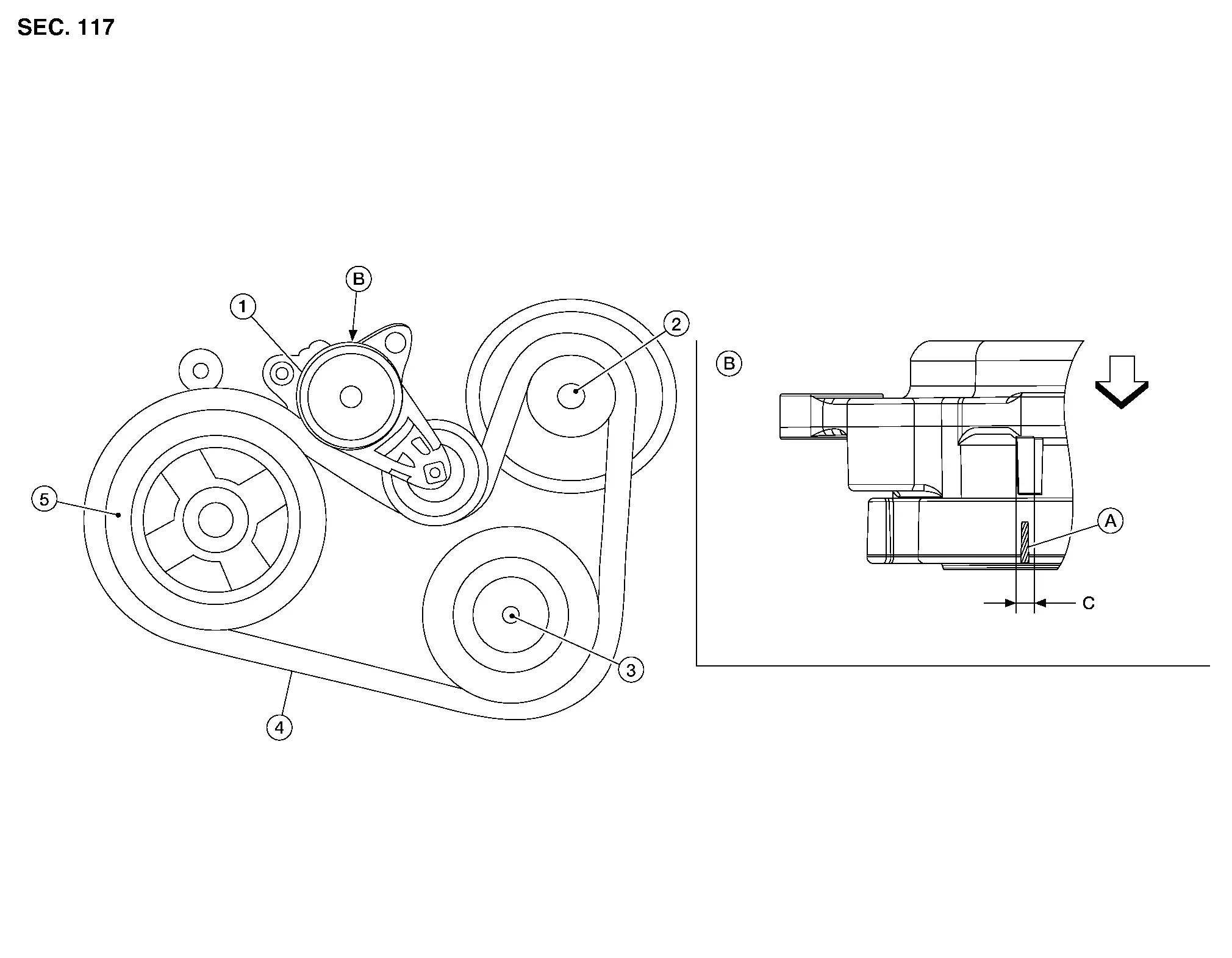
| 1. | Drive belt auto-tensioner | 2. | Generator | 3. | Compressor |
| 4. | Drive belt | 5. | Crankshaft pulley | A. | Drive belt auto-tensioner indicator |
| B. | View B | C. | Possible use range |
 |
Engine front |
Checking Drive Belt
WARNING:
Inspect and check the drive belt with the engine off.
Visually check entire drive belt for wear, damage or cracks.
Check that the drive belt auto-tensioner indicator is within the possible use range.
 NOTE:
NOTE:
-
When new drive belt is installed, the drive belt auto-tensioner indicator should be within the new drive belt range.
-
Check the drive belt auto-tensioner indicator when the engine is cold.
If the drive belt auto-tensioner indicator is out of the possible use range or drive belt is damaged, replace drive belt.
Tension Adjustment
-
Drive belt tension is automatically adjusted by the drive belt auto-tensioner
.
-
Drive belt tension is not manually adjustable.
Removal and Installation
REMOVAL
Remove the front wheel and tire (RH) using power tool. Refer to Removal and Installation.
Remove the front fender protector side cover (RH). Refer to Exploded View.
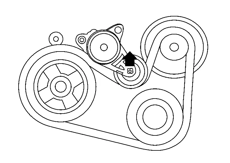
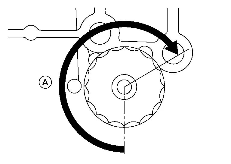
While securely holding the hexagonal part in pulley center of drive belt auto-tensioner, move in the direction of arrow (loosening direction of drive belt auto-tensioner) using suitable tool.
WARNING:
Avoid placing hand in a location where pinching may occur if the holding tool accidentally comes off.
CAUTION:
Do not loosen the drive belt auto-tensioner pulley bolt. (Do not turn it counterclockwise. If turned counterclockwise, the complete drive belt auto-tensioner must be replaced as a unit, including pulley.)
Insert a rod approximately 6 mm (0.24 in) in diameter through the rear of drive belt auto-tensioner into retaining boss to lock drive belt auto-tensioner pulley.
 NOTE:
NOTE:
Leave drive belt auto-tensioner pulley arm locked until drive belt is installed.
Remove drive belt from crankshaft pulley and then remove it from the other pulleys.
INSTALLATION
Install the drive belt onto all of the pulleys.
CAUTION:
Confirm belt is completely set on the pulleys.
Release drive belt auto-tensioner, and apply tension to drive belt.
WARNING:
Avoid placing hand in a location where pinching may occur if the holding tool accidentally comes off.
CAUTION:
Do not loosen the drive belt auto-tensioner pulley bolt. (Don't turn it counterclockwise. If turned counterclockwise, the complete drive belt auto-tensioner must be replaced as a unit, including pulley.)
Turn crankshaft pulley clockwise several times to equalize tension between each pulley.
Confirm drive belt auto-tensioner indicator is within the possible use range. Refer to Checking Drive Belt.
Install the front fender protector side cover (RH). Refer to Exploded View.
Install the front wheel and tire (RH) using power tool. Refer to Removal and Installation.
Engine Coolant Nissan Pathfinder SUV
System Inspection
WARNING:
-
Do not remove the radiator cap or reservoir tank cap when the engine is hot. Serious burns could occur from high-pressure engine coolant escaping from the cooling system.
-
When removing the radiator cap or reservoir tank cap, wrap a thick cloth around the cap and slowly turn it a quarter turn to allow built-up pressure to escape. Then carefully remove the cap by turning it all the way.
CHECKING COOLING SYSTEM HOSES
Check hoses for the following:
-
Improper attachment
-
Leaks
-
Cracks
-
Dents
-
Bulges
-
Internal obstruction
-
Damage
-
Loose connections
-
Chafing
-
Deterioration
CHECKING RESERVOIR LEVEL
-
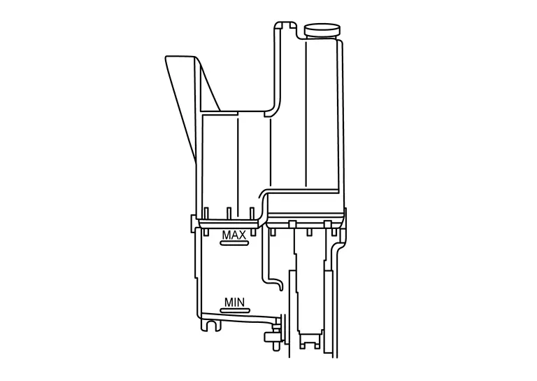
Check if the reservoir tank coolant level is within MIN to MAX when the engine is cool.
-
Adjust coolant level (if necessary), to ensure that the engine coolant level is within the MIN to MAX range.
CAUTION:
Refill Genuine NISSAN Long Life Antifreeze/Coolant (blue) or equivalent in its quality mixed with water (distilled or demineralized). Refer to Fluids and Lubricants (United States and Canada) or Fluids and Lubricants (Mexico).
CHECKING COOLING SYSTEM FOR LEAKS
WARNING:
-
Do not remove the radiator cap or reservoir tank cap when the engine is hot. Serious burns could occur from high-pressure engine coolant escaping from the cooling system.
-
When removing the radiator cap or reservoir tank cap, wrap a thick cloth around the cap and slowly turn it a quarter turn to allow built-up pressure to escape. Then carefully remove the cap by turning it all the way.
To check the cooling system for leaks, apply pressure to the cooling system using Tools (A), (B), (C) and (D).
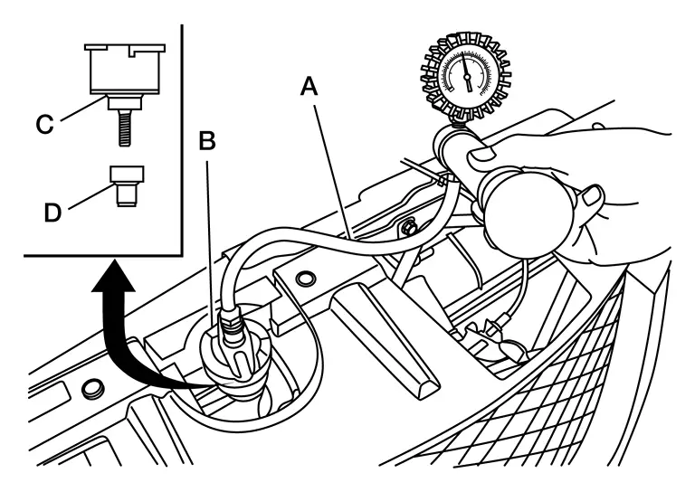
| Tool number (A) | : — (NI-51771-5) |
| Tool number (B) | : — (NI-51771-9) |
| Tool number (C) | : — (NI-51771-1) |
| Tool number (D) | : — (NI-51771-4) |
| Leakage test pressure | : Refer to Radiator. |
CAUTION:
Higher testing pressure than specified may cause radiator damage.
 NOTE:
NOTE:
-
If engine coolant decreases, replenish radiator with engine coolant. Refer to Fluids and Lubricants. (For USA and Canada) or Fluids and Lubricants (For Mexico).
-
If anything is found, repair or replace damaged parts.
CHECKING RADIATOR CAP
WARNING:
-
Do not remove the radiator cap or reservoir tank cap when the engine is hot. Serious burns could occur from high-pressure engine coolant escaping from the cooling system.
-
When removing the radiator cap or reservoir tank cap, wrap a thick cloth around the cap and slowly turn it a quarter turn to allow built-up pressure to escape. Then carefully remove the cap by turning it all the way.
-
Check the pressure valve of the radiator cap.
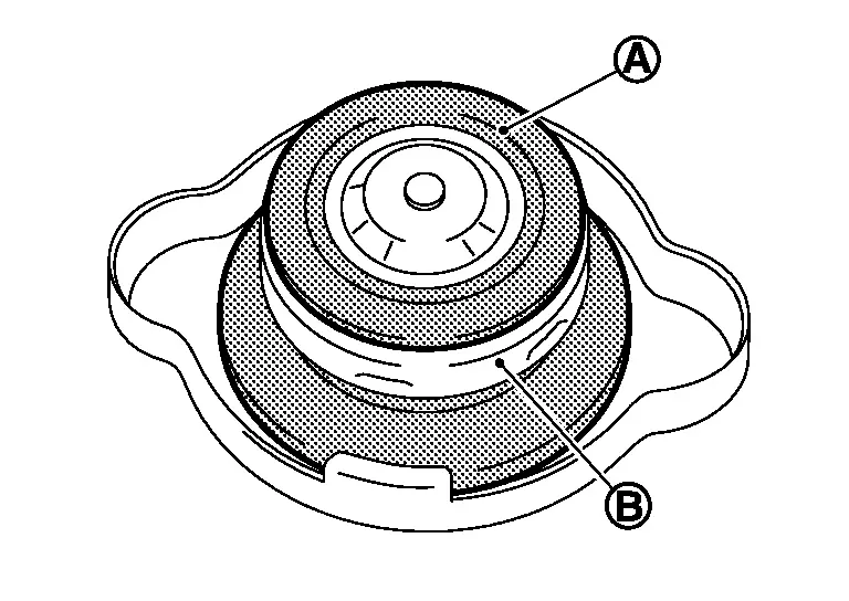
-
Replace the radiator cap if the metal plunger (B) on the pressure valve cannot be seen around the edge of the rubber gasket (A).
-
Replace the radiator cap if there is damage or deposits of foreign material on the rubber gasket or pressure valve.
CAUTION:
Thoroughly wipe out the radiator filler neck to remove any waxy residue or foreign material.
-
-
Check the negative-pressure valve of the radiator cap.
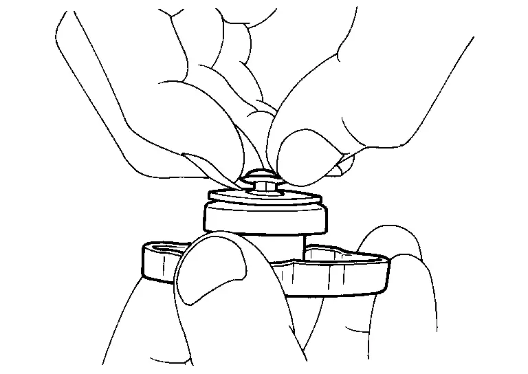
-
Replace the radiator cap if the negative-pressure valve does not close completely when pulled open and released.
-
Replace the radiator cap if there is damage or deposits of foreign material on the valve seat of the negative-pressure valve.
-
Replace the radiator cap if there is an abnormality in the operation of the negative-pressure valve.
-
-
Check radiator cap relief pressure.
-
Check the radiator cap relief pressure using Tools (A) and (B), and suitable Tool (C).
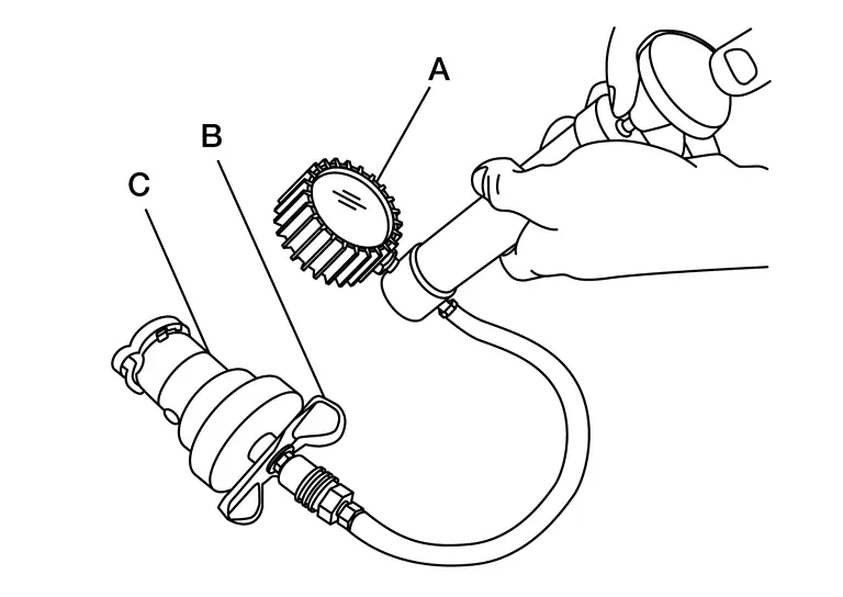
Tool number (A) : — (NI-51771-5) Tool number (B) : — (NI-51771-9) Tool number (C)
(commercially available): — (NI-33984-A or equivalent) Radiator cap relief
pressure: Refer to Radiator. -
When connecting the radiator cap to suitable Tool (C), apply water or coolant to the radiator cap seal surface.
-
Replace the radiator cap if the radiator cap relief pressure is outside of specification.
-
CHECKING RADIATOR
Check radiator for mud or clogging. If necessary, clean radiator as follows.
CAUTION:
-
Be careful not to bend or damage the radiator fins.
-
When radiator is cleaned on-Nissan Pathfinder vehicle, remove surrounding parts in order to access the radiator core. Tape the harness and electrical connectors to prevent water from entering.
-
Spray water to the back side of the radiator core using a side to side motion from the top down.
-
Stop spraying when debris no longer flows from radiator core.
-
Blow air into the back side of radiator core using a side to side motion from the top down.
-
Use compressed air lower than 490 kPa (4.9 bar, 5 kg/cm2, 71 psi) and keep distance more than 30 cm (11.8 in).
-
-
Continue to blow air until no water sprays out.
-
Check for engine coolant leaks. Repair as necessary.
Draining
WARNING:
-
Do not remove the radiator cap or reservoir tank cap when the engine is hot. Serious burns could occur from high-pressure engine coolant escaping from the cooling system.
-
When removing the radiator cap or reservoir tank cap, wrap a thick cloth around the cap and slowly turn it a quarter turn to allow built-up pressure to escape. Then carefully remove the cap by turning it all the way.
Open radiator drain plug (1) at the bottom of radiator and remove the radiator filler cap.
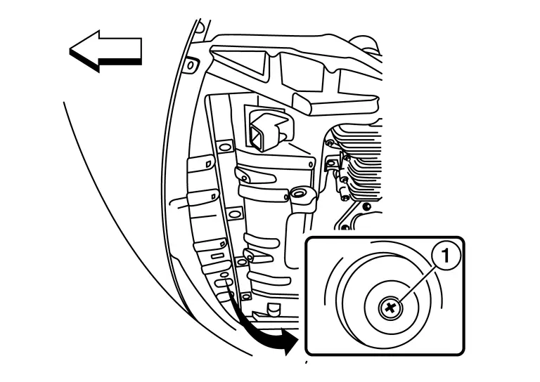
 |
: Front |
For a complete cooling system drain, remove the reservoir tank and drain the engine coolant, and then clean the reservoir tank before installation.
CAUTION:
Do not allow the engine coolant to contact the drive belt.
When performing a complete cooling system drain, remove the water drain plug (B), connector bolt (C), and copper sealing washer (A) on the cylinder block.
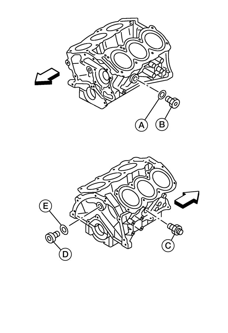
CAUTION:
Do not reuse copper sealing washers.
 NOTE:
NOTE:
Remove water drain plug (D) and copper sealing washer (E) during engine overhaul.
 |
: Engine front |
Check the drained engine coolant for contaminants such as rust, corrosion or discoloration.
-
If contaminated, flush the engine cooling system. Refer to Flushing.
Refilling
Install the following, if removed:
-
Cylinder block drain plugs, refer to Exploded View.
-
Reservoir tank, refer to Exploded View.
-
Cooling system hoses, refer to Exploded View.
-
Radiator drain plug, refer to Exploded View.
Set the Nissan Pathfinder vehicle heater controls to the full HOT and heater ON positions. Place the vehicle ignition in the "ON" position with the engine OFF as necessary to activate the heater mode.
Fill the cooling system with engine coolant using Tool (A), following the manufacturer’s instructions included with the tool.
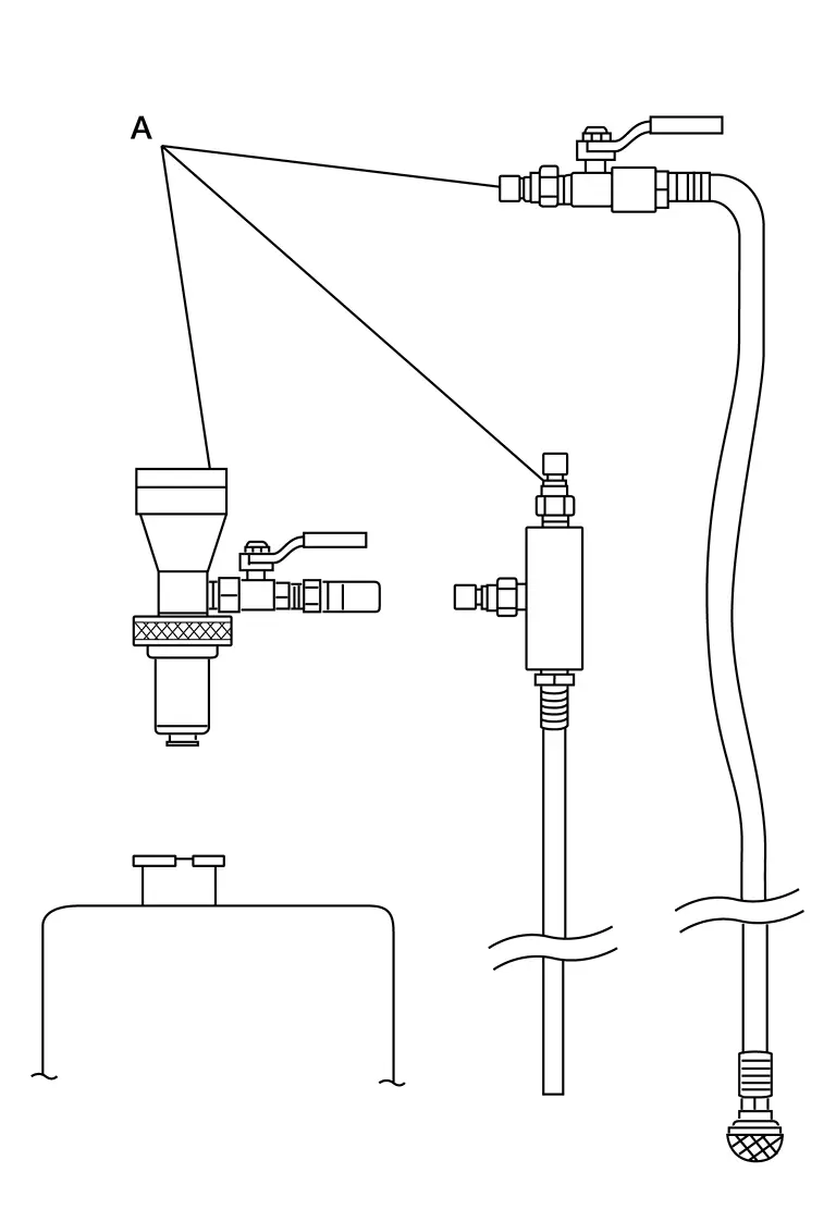
| Tool number (A) | : KV991J0070 (NI-45695-A) |
| Engine Coolant | : Refer to Fluids and Lubricants (United States and Canada) or Fluids and Lubricants (Mexico). |
CAUTION:
-
Use recommended coolant or equivalent.
-
Do not use any cooling system additives such as radiator sealer. Additives may clog the cooling system and cause damage to the engine, transmission or cooling system.
-
The compressed air supply must be equipped with an air dryer.
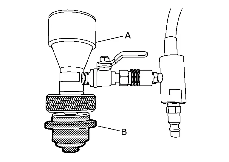
 NOTE:
NOTE:
When installing Tool (A) to radiator cap filler neck, make sure to select the correct size expansion plug (B).
Remove the Tool (A) and top off the cooling system with engine coolant as necessary.
Install the radiator cap and reservoir tank cap.
Run the engine until it reaches normal operating temperature.
CAUTION:
Do not allow the engine to exceed normal operating temperature or engine damage may occur.
Stop the engine and allow it to cool.
Check the engine coolant level and adjust if necessary.
Flushing
Fill the radiator from the filler neck above the radiator upper hose and reservoir tank with clean water and reinstall radiator filler cap.
Run the engine until it is at normal operating temperature.
Rev the engine two or three times under no-load.
Stop the engine and wait until it cools down.
Drain the water from the system.
Repeat steps 1 through 5 until clear water begins to drain from the radiator.
Fuel Lines Nissan Pathfinder
Inspection
Inspect fuel lines, fuel filler cap, and fuel tank for improper attachment, leaks, cracks, damage, loose connections, chafing or deterioration.
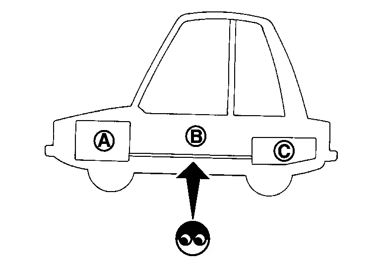
| (A) | : Engine |
| (B) | : Fuel line |
| (C) | : Fuel tank |
If necessary, repair or replace damaged parts.
Air Cleaner Filter Nissan Pathfinder 2022
Exploded View
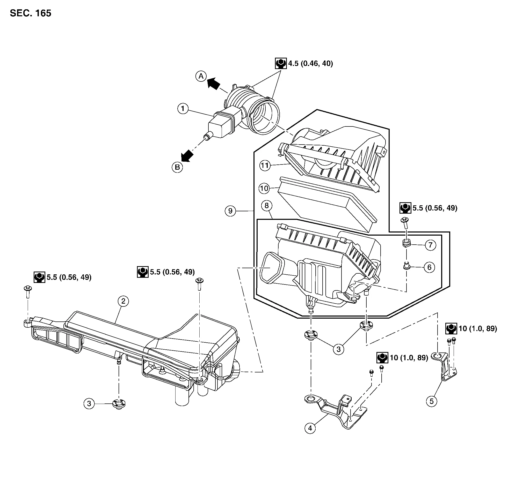
| 1. | Air duct hose and resonator assembly | 2. | Front air duct | 3. | Grommet |
| 4. | Air cleaner case mounting bracket | 5. | Bracket | 6. | Retainer |
| 7. | Mounting rubber | 8. | Air cleaner case (lower) | 9. | Air cleaner assembly |
| 10. | Air cleaner filter | 11. | Air cleaner case (upper) | A. | To electric throttle control actuator. Refer to Exploded View. |
| B. | To rocker cover (bank 1). Refer to Exploded View. |
Removal and Installation
REMOVAL
CAUTION:
It is not necessary to remove the front air duct to replace the air cleaner filter.
 NOTE:
NOTE:
Replace the air cleaner filter per the periodic maintenance schedule or as necessary. Refer to Introduction of Periodic Maintenance
Unhook air cleaner case side clips and lift air cleaner case (upper).
Remove the air cleaner filter.
INSTALLATION
Installation is in the reverse order of removal.
Engine Oil Nissan Pathfinder R53
Inspection
ENGINE OIL LEVEL
 NOTE:
NOTE:
-
Before starting engine, place vehicle on a level surface and check the engine oil level. If engine has already been started, stop it and allow 10 minutes before checking.
Remove oil level gauge and wipe it clean.
Insert oil level gauge and check that the engine oil level is within the range (A) shown.
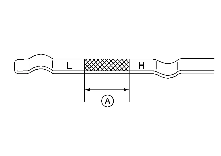
If engine oil level is out of range, add oil as necessary until oil level gauge indicates the correct level.
CAUTION:
Do not overfill the engine with oil.
 NOTE:
NOTE:
It is normal to add some oil between oil maintenance intervals or during the break-in period, depending on the severity of the operating conditions.
ENGINE OIL APPEARANCE
-
Check engine oil for white milky appearance or excessive contamination.
-
If engine oil becomes milky, it is highly probable that it is contaminated with engine coolant. Repair or replace damaged parts.
ENGINE OIL LEAKS
Check for engine oil leaks around the following areas:
-
Oil pan (upper)
-
Oil pan (lower)
-
Oil pan drain plug
-
Engine oil pressure sensor
-
Engine oil temperature sensor
-
Oil filter
-
Oil cooler
-
Valve timing control cover
-
Exhaust valve timing control solenoid valve
-
Front timing chain case
-
Mating surface between rear timing chain case and cylinder head
-
Mating surface between rear timing chain case and cylinder block
-
Mating surface between rear timing chain case and oil pan (upper)
-
Mating surface between rear timing chain case and front timing chain case
-
Mating surface between cylinder block and cylinder head
-
Mating surface between cylinder head and rocker cover
-
Crank oil seal (front and rear)
-
Engine oil pressure control solenoid valve
-
Camshaft position sensor
-
Exhaust camshaft position sensor
-
Intake camshaft position sensor
-
High pressure fuel pump
Draining
WARNING:
-
Be careful not to burn yourself, as the engine oil may be hot.
-
Prolonged and repeated contact with used engine oil may cause skin cancer; try to avoid direct skin contact with used engine oil. If skin contact is made, wash thoroughly with soap or hand cleaner as soon as possible.
Position the vehicle so it is level on the hoist.
Warm up the engine and check for engine oil leaks. Refer to Inspection.
Stop engine and wait for 10 minutes.
Remove the front under cover. Refer to Removal and Installation.
Loosen oil filler cap.
Remove the oil pan drain plug and drain the engine oil.
Refilling
Install drain plug with new drain plug washer.
CAUTION:
-
Do not reuse drain plug washer.
-
Be sure to clean drain plug and install with new drain plug washer.
| Tightening torque | : Refer to Exploded View. |
Refill with new engine oil.
CAUTION:
-
The refill capacity depends on the engine oil temperature and drain time. Use these specifications for reference only.
-
Always use oil level gauge to determine the proper amount of engine oil in the engine.
| Engine oil specification and capacity | : Refer to Fluids and Lubricants. |
Warm up engine and check area around drain plug and oil filter for engine oil leaks.
Install front under cover. Refer to Removal and Installation.
Stop engine and wait 10 minutes.
Check engine oil level. Refer to Inspection.
Oil Filter Nissan Pathfinder SUV
Removal and Installation
REMOVAL
Drain engine oil. Refer to Draining.
Remove front fender protector side cover (RH). Refer to Exploded View.
Remove the oil filter using suitable tool.
WARNING:
Be careful not to get burned; the engine oil may be hot.
CAUTION:
-
Position a shop cloth to absorb any oil leaks or spills.
-
Do not allow engine oil to contact the drive belts.
-
Completely wipe off any oil that contacts to the engine or the Nissan Pathfinder vehicle.
-
The oil filter is provided with a relief valve.
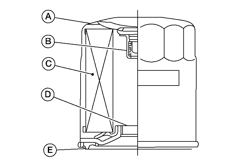
(A) : Oil filter body (B) : Relief valve (C) : Filtering paper (D) : Screw (E) : Packing
 NOTE:
NOTE:
It is recommended to use a Genuine NISSAN oil filter or equivalent. The use of parts that do not meet or exceed NISSAN specifications may cause damage to the Nissan Pathfinder vehicle, and have an effect on warranty coverage. Always check with the Parts Department for the latest parts information.
INSTALLATION
Remove foreign materials adhering to the oil filter installation surface.
Apply clean engine oil to the oil seal contact surface of the new oil filter.
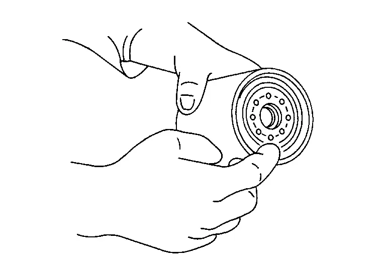
Screw the oil filter manually until it touches the installation surface, then tighten it by turning another 2/3 turn (A), or tighten to specification using a suitable tool.
| Oil filter | : 18.0 N·m (1.8 kg-m, 13 ft-lb) |
Refill the engine with new engine oil. Refer to Refilling.
Check the oil level and add engine oil as necessary. Refer to Inspection.
After warming up the engine, check for engine oil leaks.
Install front fender protector side cover (RH). Refer to Exploded View.
Spark Plug Nissan Pathfinder Fifth generation
Exploded View
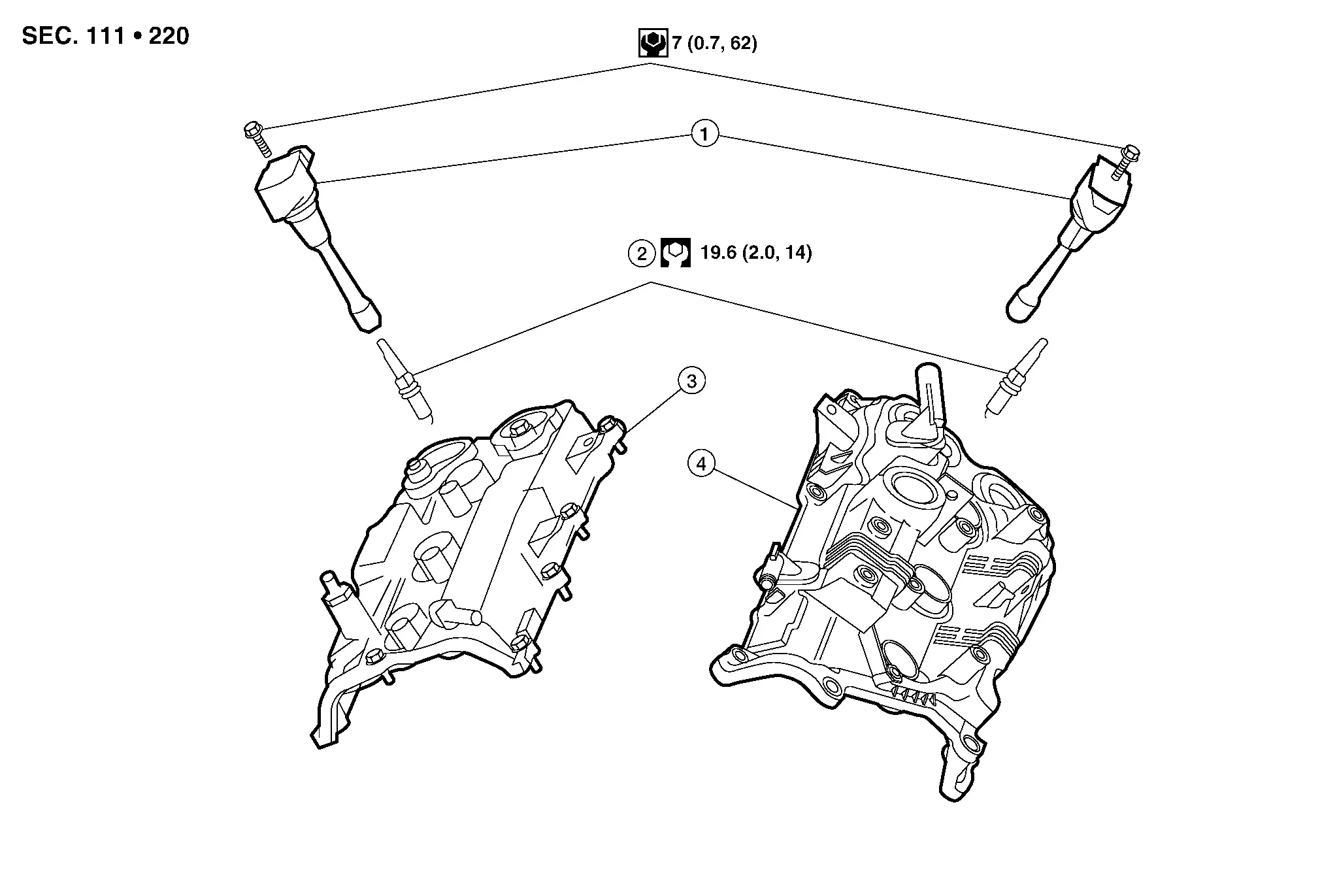
| 1. | Ignition coil | 2. | Spark plug | 3. | Rocker cover (Bank 1) |
| 4. | Rocker cover (Bank 2) |
Removal and Installation
REMOVAL
Remove the ignition coil. Refer to Removal and Installation (Bank 2) (Bank 2) and Removal and Installation (Bank 1) (Bank 1).
Remove the spark plug using Tool.
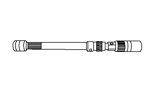
| Tool number | : — (NI-48891) |
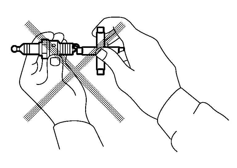
INSPECTION AFTER REMOVAL
Use the standard type spark plug for normal condition.
| Spark plug | : Refer to Spark Plug. |
CAUTION:
-
Do not drop or shock spark plug. Discard spark plug if dropped.
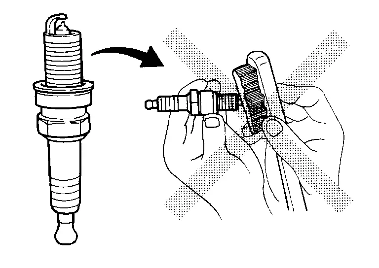
-
Do not use a wire brush for cleaning.
-
If plug is covered with carbon, a spark plug cleaner may be used.
| Cleaner air pressure | : less than 588 kPa (5.88 bar, 6 kg/cm2, 85 psi) |
| Cleaning time | : less than 20 seconds |
-
Spark plug gap adjustment is not required between replacement intervals.
-
Measure spark plug gap. When it exceeds the limit, replace spark plug even if it is within the specified replacement mileage. Refer to Spark Plug.
INSTALLATION
Installation is in the reverse order of removal.
| Make | DENSO |
| Standard type* | FXE22HR11 |
| Gap (nominal) | 1.1 mm (0.043 in) |
*: Always check with the Parts Department for the latest parts information.
Evap Vapor Lines Nissan Pathfinder Fifth generation
Inspection
Visually inspect EVAP vapor lines for improper attachment and for cracks, damage, loose connections, chafing and deterioration.
Inspect fuel tank filler cap vacuum relief valve for clogging, sticking, etc.

Nissan Pathfinder (R53) 2022-2026 Service Manual
Engine Maintenance
Contact Us
Nissan Pathfinder Info Center
Email: info@nipathfinder.com
Phone: +1 (800) 123-4567
Address: 123 Pathfinder Blvd, Nashville, TN 37214, USA
Working Hours: Mon–Fri, 9:00 AM – 5:00 PM (EST)
