Nissan Pathfinder: Maintenance - Chassis and Body Maintenance
- In-Cabin Microfilter
- Exhaust System
- A/t Fluid
- Transfer Oil
- Rear Differential Gear Oil
- Propeller Shaft
- Wheels
- Brake Fluid Level and Leaks
- Brake Lines and Cables
- Brake Fluid
- Front Brake
- Steering Gear and Linkage
- Axle and Suspension Parts
- Locks, Hinges and Hood Latch
- Seat Belt, Buckles, Retractors, Anchors and Adjusters
In-Cabin Microfilter Nissan Pathfinder R53
Removal and Installation
REMOVAL
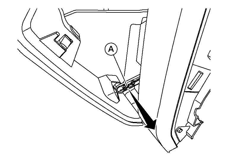
Using a suitable tool, release glove box lid dampener (A) as shown.
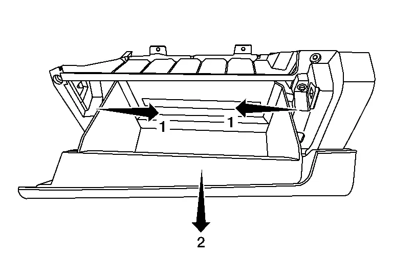
Release stoppers as shown, then lower glove box assembly lid.
Release in-cabin microfilter release tab, then remove in-cabin microfilter cover.
CAUTION:
Use care when releasing in-cabin microfilter release tab to avoid damaging it.
Remove in-cabin microfilter. Refer to Exploded View.
CAUTION:
If in-cabin microfilter is deformed/damaged when removing, replace it with a new one. A deformed or damaged in-cabin microfilter may affect dust collecting performance.
INSTALLATION
Installation is in the reverse order of removal.
CAUTION:
When installing, handle in-cabin microfilter with extreme care to avoid deforming or damaging it.
 NOTE:
NOTE:
The in-cabin microfilter is marked with an air flow arrow. The end of the in-cabin microfilter with the arrow should face the passenger side of the Nissan Pathfinder vehicle. The arrow should point toward the bottom of the vehicle.
Exhaust System Nissan Pathfinder 2026
Inspection
Check exhaust pipes, muffler and mounting for improper attachment, leaks, cracks, damage or deterioration. Repair or replace as necessary.
A/t Fluid Nissan Pathfinder Fifth generation
Inspection
FLUID LEAKAGE
-
Check transaxle surrounding area (oil seal and plug etc.) for fluid leakage.
-
If anything is found, repair or replace damaged parts and adjust A/T fluid level. Refer to Adjustment.
Replacement
| A/T fluid | : Refer to General Specification. |
| Fluid capacity | : Refer to General Specification. |
CAUTION:
-
Always use shop paper. Never use shop cloth.
-
Use caution when looking into the drain hole as there is a risk of dripping fluid entering the eye.
-
After replacement, always perform A/T fluid leak check.
Select “Data Monitor” in “TRANSMISSION” using CONSULT.
Select “FLUID TEMP” and confirm that the A/T fluid temperature is between 35°C and 45°C (95°F to 113°F).
Check that the selector lever is in the “P” position, then completely engage the parking brake.
Lift up the Nissan Pathfinder vehicle.
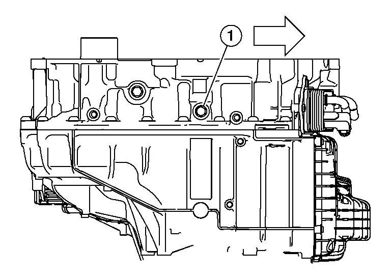
Remove the drain plug (1) and drain the A/T fluid from A/T case.
 |
: Nissan Pathfinder Vehicle front |
Install the drain plug to specified torque. Refer to Exploded View.
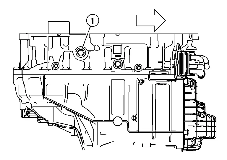
Remove the fill plug (1).

 |
: Nissan Pathfinder Vehicle front |
Install the charging pipe set (A/T stand pipe adapter kit) KV311039S0 (NI-52584) into the overflow plug hole.
CAUTION:
Tighten the charging pipe by hand.
Install the ATF changer hose to the charging pipe.
CAUTION:
Press the ATF changer hose all the way onto the charging pipe until it stops.
Fill approximately 7 liter (7-1/2 US qt, 6-1/4 lmp qt) of the A/T fluid.
Remove the ATF changer hose and charging pipe, then install and finger tighten the fill plug.
 NOTE:
NOTE:
Perform this work quickly because A/T fluid leaks.
Start the engine.
Park the Nissan Pathfinder vehicle on a level surface with the engine running and parking brake set.
Using CONSULT-III plus, ensure that the A/T fluid temperature is between 95°F to 113°F (35°C to 45°C).
With Nissan Pathfinder vehicle in PARK and A/T fluid temperature in correct range, let engine run at 2000 rpm for about 10 seconds.
Shift the transmission into REVERSE for 10 seconds.
Shift the transmission into DRIVE for 10 seconds.
Shift the transmission into 1st for 10 seconds.
Shift the transmission into 2nd for 10 seconds.
Shift the transmission into 3rd for 10 seconds.
Shift the transmission into 4th for 10 seconds.
CAUTION:
Do not exceed 4th gear or transmission damage can occur.
Shift the transmission into NEUTRAL until wheels come to a complete stop.
Shift the transmission into PARK.
Lift up the Nissan Pathfinder vehicle.
Remove the fill plug (1).
 |
: Nissan Pathfinder Vehicle front |
If A/T fluid flows out of fill hole, let A/T fluid flow out until flow is reduced to a thin stream and then install fill plug and tighten to specification. If A/T fluid does not run out of fill hole repeat steps 1–18 adding small quantities of A/T fluid at a time.
Adjustment
| A/T fluid | : Refer to General Specification. |
| Fluid capacity | : Refer to General Specification. |
CAUTION:
-
During adjustment of the A/T fluid level, check CONSULT so that the oil temperature may be maintained from 35°C to 45°C (95°F to 113°F).
-
Use caution when looking into the drain hole as there is a risk of dripping fluid entering the eye.
-
After replacement, always perform A/T fluid leak check.
Remove the fill plug (1).

 |
: Nissan Pathfinder Vehicle front |
Install the charging pipe set (A/T stand pipe adapter kit) KV311039S0 (NI-52584) into the overflow plug hole.
CAUTION:
Tighten the charging pipe by hand.
Install the ATF changer hose to the charging pipe.
CAUTION:
Press the ATF changer hose all the way onto the charging pipe until it stops.
Fill A/T with small amount of the A/T fluid.
Remove the ATF changer hose and charging pipe, then install and finger tighten the fill plug.
 NOTE:
NOTE:
Perform this work quickly because A/T fluid leaks.
Start the engine.
Park the Nissan Pathfinder vehicle on a level surface with the engine running and parking brake set.
Using CONSULT-III plus, ensure that the A/T fluid temperature is between 95°F to 113°F (35°C to 45°C).
With Nissan Pathfinder vehicle in PARK and A/T fluid temperature in correct range, let engine run at 2000 rpm for about 10 seconds.
Shift the transmission into REVERSE for 10 seconds.
Shift the transmission into DRIVE for 10 seconds.
Shift the transmission into 1st for 10 seconds.
Shift the transmission into 2nd for 10 seconds.
Shift the transmission into 3rd for 10 seconds.
Shift the transmission into 4th for 10 seconds.
CAUTION:
Do not exceed 4th gear or transmission damage can occur.
Shift the transmission into NEUTRAL until wheels come to a complete stop.
Shift the transmission into PARK.
Lift up the Nissan Pathfinder vehicle.
Remove the fill plug (1).

 |
: Nissan Pathfinder Vehicle front |
If A/T fluid flows out of fill hole, let A/T fluid flow out until flow is reduced to a thin stream and then install fill plug and tighten to specification. If A/T fluid does not run out of fill hole repeat steps 1–18 adding small quantities of A/T fluid at a time.
Transfer Oil Nissan Pathfinder 2022
Inspection
TRANSFER OIL LEAKS
Check that transfer oil is not leaking from transfer assembly or around it.
TRANSFER OIL LEVEL
CAUTION:
Do not start engine while checking transfer oil level.
Remove front under cover. Refer to Removal and Installation.
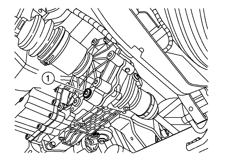
Remove filler plug (1) and gasket.
![]()
|
|
: Front |
Transfer oil level (A) should be level with bottom of filler plug hole. Add transfer oil if necessary. Refer to Fluids and Lubricants (United States and Canada) or Fluids and Lubricants (Mexico).
Set a new gasket onto filler plug, and install it in the transfer and tighten to specified torque. Refer to Exploded View.
CAUTION:
Do not reuse gasket.
Draining
CAUTION:
Do not start engine while working.
Run the vehicle to warm up the transfer unit sufficiently.
Stop the engine.
Remove front under cover. Refer to Removal and Installation.
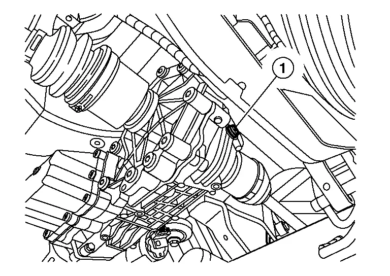
Remove drain plug (1) and gasket and drain the transfer oil.
![]()
|
|
: Front |
Set a new gasket onto filler plug, and install it in the transfer and tighten to specified torque. Refer to Exploded View.
CAUTION:
Do not reuse gasket.
Refilling
CAUTION:
Do not start engine while checking transfer oil level.
Remove front under cover. Refer to Removal and Installation.
Remove filler plug (1) and gasket.
![]()
Fill with new transfer oil to the specified level near the filler plug hole.
|
|
: Front |
| Transfer oil grade and viscosity | : Refer to Fluids and Lubricants (United States and Canada) or Fluids and Lubricants (Mexico). |
| Transfer oil capacity | : Refer to General Specifications. |
Set a new gasket onto filler plug, and install it in the transfer and tighten to specified torque. Refer to Exploded View.
CAUTION:
Do not reuse gasket.
Rear Differential Gear Oil Nissan Pathfinder SUV
Inspection
REAR DIFFERENTIAL GEAR OIL LEAKS
Check that rear differential gear oil is not leaking from final drive assembly or around it.
REAR DIFFERENTIAL GEAR OIL LEVEL
CAUTION:
Do not start engine while checking rear differential gear oil level.
Remove and discard filler plug (1).

CAUTION:
Do not reuse filler plug.
 |
: Front |
Rear differential gear oil level should be level with the bottom of filler plug hole. Add rear differential gear oil if necessary. Refer to Fluids and Lubricants (United States and Canada) or Fluids and Lubricants (Mexico).
Install filler plug (1) and tighten to specified torque. Refer to Exploded View.
Draining
CAUTION:
Do not start engine while checking rear differential gear oil level.
Remove and discard drain plug (1), and drain rear differential gear oil.
CAUTION:
Do not reuse drain plug.
 |
: Front |
Install drain plug (1) and tighten to specified torque. Refer to Exploded View.
Refilling
CAUTION:
Do not start engine while checking rear differential gear oil level.
Remove and discard filler plug (1).
CAUTION:
Do not reuse filler plug.
 |
: Front |
Fill with new rear differential gear oil to the specified level near the filler plug hole.
| Rear differential gear oil grade and viscosity | : Refer to Fluids and Lubricants (United States and Canada) or Fluids and Lubricants (Mexico). |
| Rear differential gear oil capacity | : Refer to General Specification. |
Install filler plug (1) and tighten to specified torque. Refer to Exploded View.
Propeller Shaft Nissan Pathfinder 5th Gen
Inspection
APPEARANCE AND NOISE INSPECTION
-
Inspect the propeller shaft tube for dents or cracks. If damaged, replace the propeller shaft assembly.
-
Check bearings for noise or damage. If damaged, replace as necessary.
PROPELLER SHAFT VIBRATION
 NOTE:
NOTE:
If vibration is present at high speed, check propeller shaft runout first, then check mounting between propeller shaft and companion flange.
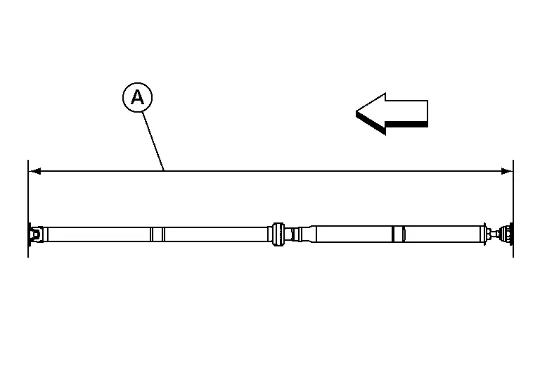
Measure the runout of the propeller shaft tube at several points by rotating the final drive companion flange with your hands.
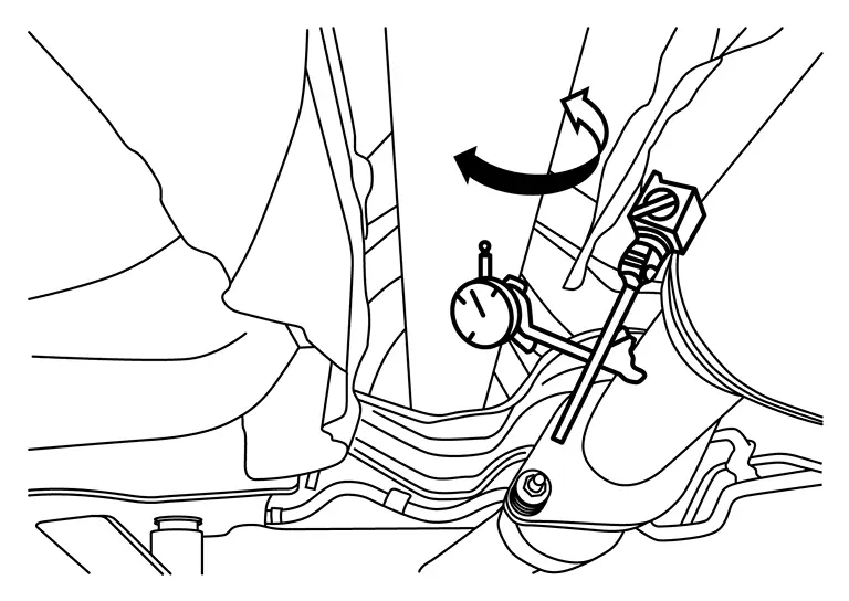
| Propeller shaft runout | : Refer to Propeller Shaft Runout. |
| A. | Runout measure range |
 |
: Front |
If the runout still exceeds specifications, disconnect the propeller shaft at the final drive companion flange; then rotate the companion flange 90°, 180°, 270° and reconnect propeller shaft.
Check the runout again. If the runout still exceeds specifications, replace the propeller shaft assembly.
After installation, check for vibration by driving the Nissan Pathfinder vehicle.
Wheels Nissan Pathfinder Fifth generation
Inspection
Check tires for wear and improper inflation.
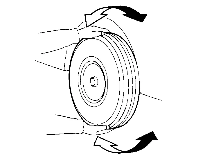
Check wheels for deformation, cracks and other damage. If deformed, remove wheel and check wheel runout.
Remove tire from wheel and mount wheel on a balancer machine.
CAUTION:
DO NOT use center hole cone-type clamping machines to hold the wheel during tire removal/installation or balancing or damage to the wheel paint, cladding or chrome may result. Use only rim-type or universal lug-type clamping machines to hold the wheel during servicing.
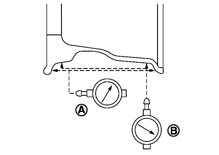
Set dial indicator as shown. Check runout. If the lateral runout (A) or radial runout (B) exceeds the limit, replace wheel.| Lateral runout (A) | Refer to Wheel. |
| Radial runout (B) | Refer to Wheel. |
Adjustment
BALANCING WHEELS (ADHESIVE WEIGHT TYPE)
Preparation Before Adjustment
Remove inner and outer balance weights from the wheel. Using releasing agent, remove double-faced adhesive tape from the wheel.
CAUTION:
-
Be careful not to scratch the wheel and tire during removal.
-
After removing double-faced adhesive tape, wipe clean all traces of releasing agent from the wheel and tire.
Wheel Balance Adjustment
CAUTION:
-
DO NOT use center hole cone-type clamping machines to hold the wheel during tire removal/installation or balancing or damage to the wheel paint, cladding or chrome may result. Use only rim-type or universal lug-type clamping machines to hold the wheel during servicing.
-
If a balancer machine has an adhesive weight mode setting, select the adhesive weight mode setting and skip Step 2 below. If a balancer machine only has the clip-on (rim flange) weight mode setting, follow Step 2 to calculate the correct size adhesive weight.
-
Set wheel and tire on balancer machine using the center hole as a guide. Start the balancer machine.
-
For balancer machines that only have a clip-on (rim flange) weight mode setting, follow this step to calculate the correct size adhesive weight to use. When inner and outer imbalance values are shown on the balancer machine indicator, multiply outer imbalance value by 5/3 (1.67) to determine balance weight that should be used. Select the outer balance weight with a value closest to the calculated value above and install in to the designated outer position of or at the designated angle in relation to the wheel and tire.
-
Indicated imbalance value × 5/3 (1.67) = balance weight to be installed
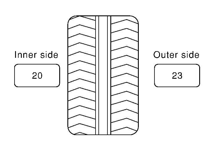
Calculation example:
23 g (0.81 oz) × 5/3 (1.67) = 38.33 g (1.35 oz) ⇒ 40 g (1.41 oz) balance weight (closer to calculated balance weight value)
 NOTE:
NOTE:
Note that balance weight value must be closer to the calculated balance weight value.
Example:
37.4 ⇒ 35 g (1.23 oz)
37.5 ⇒ 40 g (1.41 oz)
-
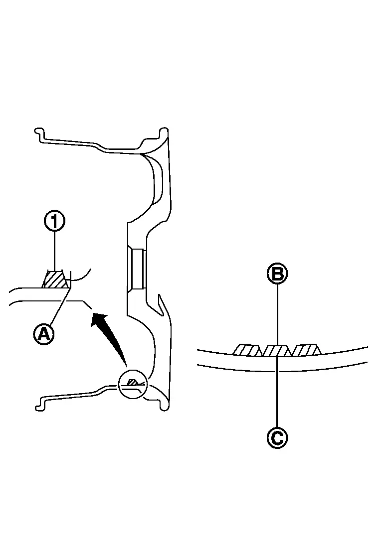
Install balance weight in the position shown.
CAUTION:
-
Do not install the inner balance weight before installing the outer balance weight.
-
Before installing the balance weight, be sure to clean the mating surface of the wheel and tire.
-
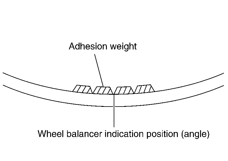
When installing balance weight (1) to wheel and tire, set it into the grooved area (A) on the inner wall of the wheel and tire as shown so that the balance weight center (B) is aligned with the balancer machine indication position (angle) (C).
CAUTION:
-
Always use Genuine NISSAN adhesive balance weights.
-
Balance weights are non-reusable; always replace with new ones.
-
Do not install more than three sheets of balance weights.
-
-
-
If calculated balance weight value exceeds 50 g (1.76 oz), install two balance weight sheets in line with each other as shown.
CAUTION:
Do not install one balance weight sheet on top of another.
-
-
Start balancer machine again.
-
Install balance weight on inner side of wheel and tire in the balancer machine indication position (angle).
CAUTION:
Do not install more than two balance weights.
-
Start balancer machine. Make sure that inner and outer residual imbalance values are 5 g (0.17 oz) each or below.
-
If either residual imbalance value exceeds 5 g (0.17 oz), repeat installation procedures.
| Wheel balance | Dynamic (At flange) | Static (At flange) |
|---|---|---|
| Allowable imbalance | Refer to Wheel. | |
Brake Fluid Level and Leaks Nissan Pathfinder R53
Inspection
BRAKE FLUID LEVEL
-
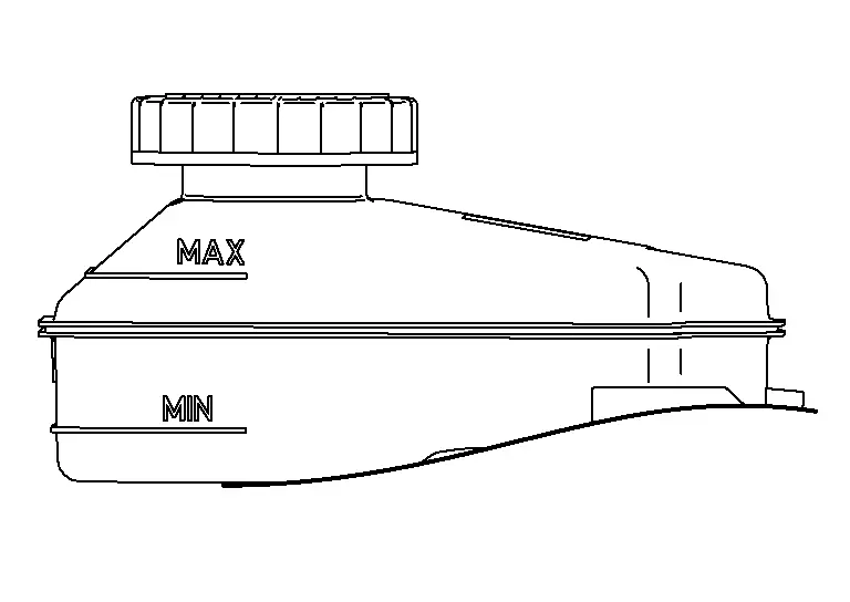
Make sure that the brake fluid level in the reservoir tank is between the MAX and MIN lines.
-
Visually check around the reservoir tank and the sub tank for brake fluid leaks.
-
If the brake fluid level is excessively low, check the brake system for leaks.
-
If the brake warning lamp remains illuminated after the parking brake is released, check the brake system for brake fluid leaks.
Brake Lines and Cables Nissan Pathfinder SUV
Inspection
-
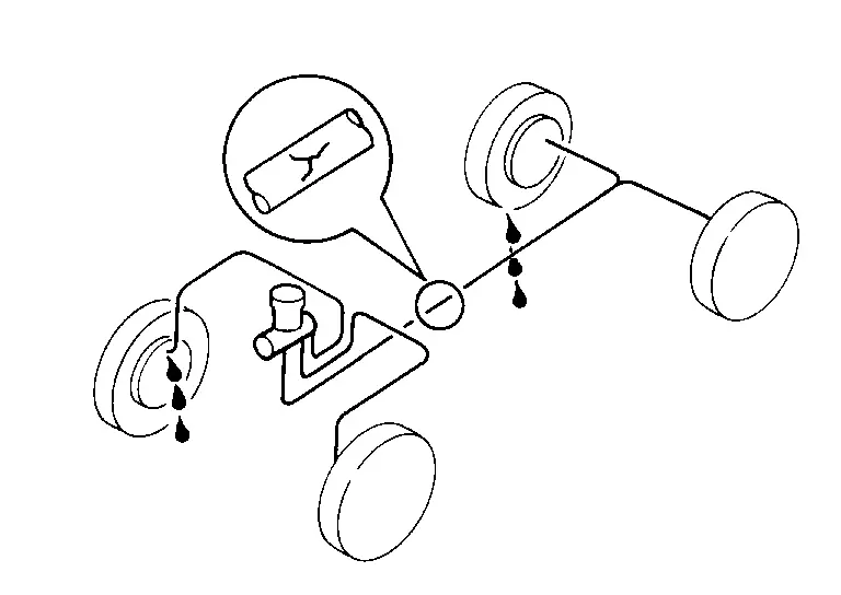
Check brake fluid lines and parking brake cables for improper attachment, leaks, chafing, abrasions, deterioration, etc.
Brake Fluid Nissan Pathfinder 2022
Draining
CAUTION:
-
Do not spill or splash brake fluid on painted surfaces. Brake fluid may damage paint. If brake fluid is splashed on painted areas, wash it away with water immediately.
-
Do not operate the brake pedal with the reservoir tank cap removed. Failure to do this may cause a discharge of brake fluid from the reservoir tank cap opening.
-
Check that there is no foreign material in the reservoir tank or in the sub tank.
-
Do not allow oils other than brake fluid to enter the reservoir tank.
-
Do not reuse drained brake fluid.
-
Do not operate the brake pedal excessively during the work procedure.
DRAINING
Connect a vinyl tube to the bleeder valve.
Depress the brake pedal and loosen the bleeder valve.
Depress the brake pedal several times and gradually discharge brake fluid.
CAUTION:
Do not allow the reservoir tank and the sub tank to empty as this may cause damage to the master cylinder internal components.
Refilling
CAUTION:
-
Do not spill or splash brake fluid on painted surfaces. Brake fluid may damage paint. If brake fluid is splashed on painted areas, wash it away with water immediately.
-
Do not operate the brake pedal with the reservoir tank cap removed. Failure to do this may cause a discharge of brake fluid from the reservoir tank cap opening.
-
Check that there is no foreign material in the reservoir tank or in the sub tank.
-
Do not allow oils other than brake fluid to enter the reservoir tank.
-
Do not reuse drained brake fluid.
-
Monitor the brake fluid level in the reservoir tank while performing the air bleeding.
-
Refill the brake system with new brake fluid. Refer to Fluids and Lubricants (FOR USA AND CANADA) or to Fluids and Lubricants (FOR MEXICO).
-
Do not operate the brake pedal excessively during the work procedure.
REFILLING
Make sure that there is no foreign material in the reservoir tank or in the sub tank, and refill with new brake fluid. Refer to Fluids and Lubricants (FOR USA AND CANADA) or to Fluids and Lubricants (FOR MEXICO).
Connect a vinyl tube to the bleeder valve.
Depress the brake pedal.
Loosen the bleeder valve.
Slowly depress the brake pedal to 2/3 of the brake pedal full stroke.
Tighten the bleeder valve with the brake pedal depressed.
Repeat this procedure at intervals of two or three seconds until all old brake fluid is discharged. Add new brake fluid to the reservoir tank frequently.
CAUTION:
Do not allow the reservoir tank and the sub tank to empty as this may cause damage to the master cylinder internal components.
Bleed the air out of the brake system. Refer to Bleeding Brake System.
Front Brake Nissan Pathfinder 5th Gen
Inspection of Pad
INSPECTION
Check brake pad wear thickness from inspection holes (A) on cylinder body.
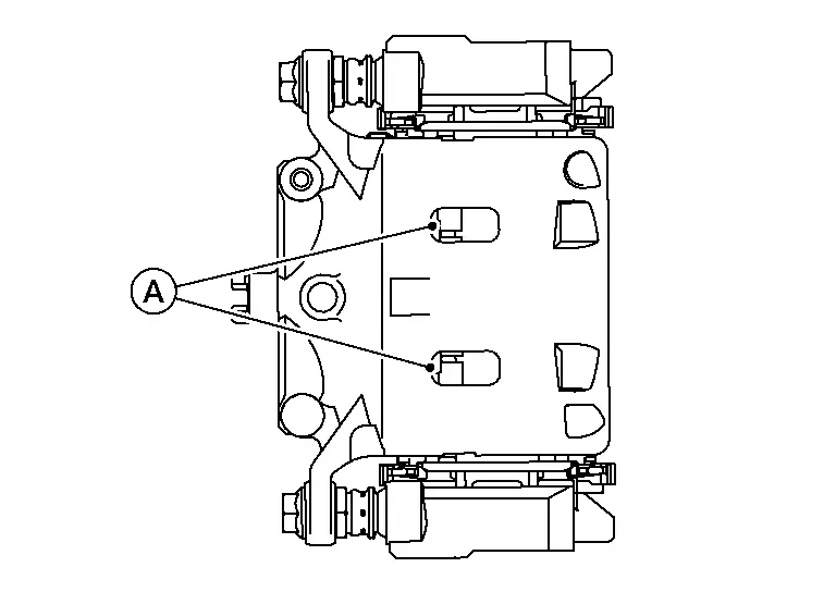
| Wear thickness | : Refer to Front Disc Brake. |
Inspection of Rotor
APPEARANCE
Check the surface of the disc brake rotor for uneven wear, cracks, or damage. Replace the disc brake rotor if any abnormal conditions exist. Refer to Removal and Installation.
RUNOUT
Check the wheel bearing axial end play before the inspection. Refer to Inspection.
Secure the disc brake rotor to the wheel hub with wheel nuts at two wheel nut locations.
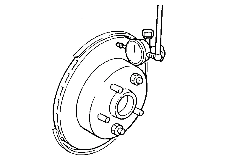
Measure the runout using a dial indicator to 10 mm (0.39 in) from the disc brake rotor edge.
| Runout (with it attached to the Nissan Pathfinder vehicle) | : Refer to Front Disc Brake. |
Find the installation position with the minimum runout by shifting the disc brake rotor-to-wheel hub installation position by one hole at a time if the runout exceeds the limit value.
Refinish the disc brake rotor if the runout is outside the limit even after performing the above operation. When refinishing, use Tool.
| Tool number | : 38-PFM92 ( — ) |
CAUTION:
-
Check in advance that the thickness of the disc brake rotor is wear thickness + 0.3 mm (0.012 in) or more.
-
If the thickness is less than wear thickness + 0.3 mm (0.012 in), replace the disc brake rotor. Refer to Removal and Installation.
| Wear thickness | : Refer to Front Disc Brake. |
THICKNESS
Check the thickness of the disc brake rotor using a micrometer. Replace the disc brake rotor if the thickness is below the wear limit. Refer to Removal and Installation.
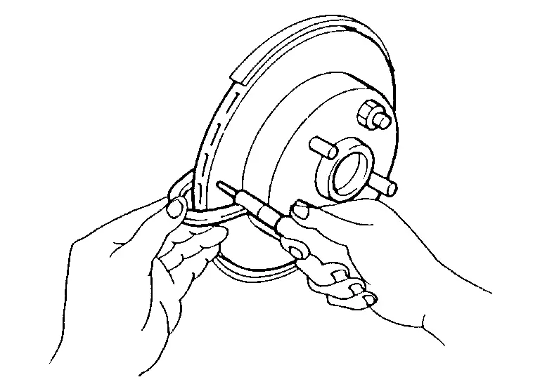
| Wear thickness | : Refer to Front Disc Brake. |
Steering Gear and Linkage Nissan Pathfinder
Inspection
STEERING GEAR
-
Check gear housing and boots for looseness, damage and grease leakage.
-
Check connection with steering column for looseness.
(A) : Check for grease leakage (B) : Check for looseness 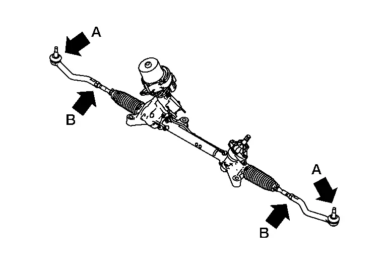
STEERING LINKAGE
Check ball joint, dust cover and other component parts for looseness, wear, damage and grease leakage.
Axle and Suspension Parts Nissan Pathfinder
Inspection
Check front and rear axle and suspension parts for excessive play, cracks, wear or other damage.
-
Shake each wheel to check for excessive play.
-
Check wheel bearings for smooth operation.
-
Check axle and suspension nuts and bolts for looseness.
-
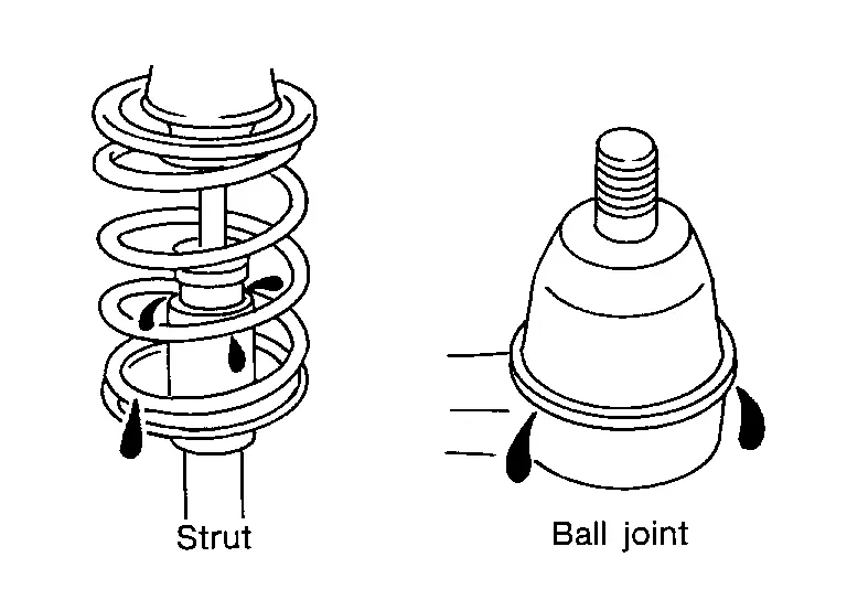
Check strut (shock absorber) for oil leakage or other damage.
-
Check suspension ball joint for grease leakage and ball joint dust cover for cracks or other damage.
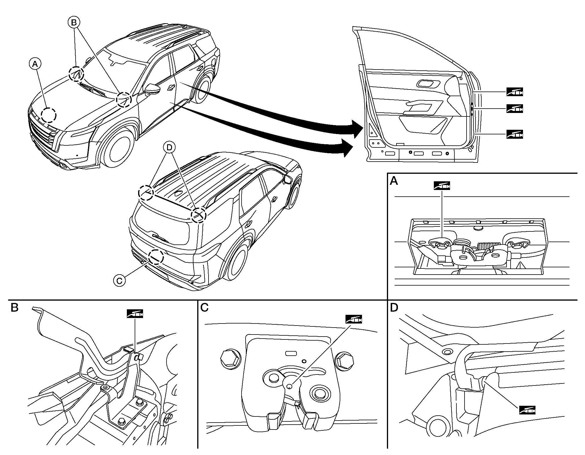
Locks, Hinges and Hood Latch Nissan Pathfinder 2026
Lubricating
 NOTE:
NOTE:
Lubricate the locations shown with a suitable multi-purpose grease.
Seat Belt, Buckles, Retractors, Anchors and Adjusters Nissan Pathfinder SUV
Inspection
For details, refer to Inspection in SB section.
-
Check anchors for loose mounting.
-
Check belts for damage.
-
Check retractor for smooth operation.
-
Check function of buckles and tongues when buckled and released.
CAUTION:
-
After any collision, inspect all seat belt assemblies, including retractors and other attached hardware (i.e., anchor bolt, guide rail set). NISSAN recommends replacing all seat belt assemblies in use during a collision, unless not damaged and properly operating after minor collision.
Also inspect seat belt assemblies not in use during a collision and replace if damaged or improperly operating.
Seat belt pre-tensioner should be replaced even if the seat belts are not in use during a frontal collision where the driver and passenger air bags are deployed.
-
If any component of seat belt assembly is questionable, do not repair.
Replace as seat belt assembly.
-
If webbing is cut, frayed, or damaged, replace belt assembly.
-
Do not oil tongue and buckle.
-
Use a Genuine NISSAN seat belt assembly.