Nissan Pathfinder: Audio, Visual & Navigation System - Ecu Diagnosis Information
Av Control Unit Nissan Pathfinder 5th Gen
Values On The Diagnosis Tool
 NOTE:
NOTE:
The following table includes information (items) inapplicable to this Nissan Pathfinder vehicle. For information (items) applicable to this vehicle, refer to CONSULT display items.
| Monitor Item | Condition | Value/Status | |
|---|---|---|---|
| Sunload sensor | Ignition switch ON | On | |
| Off | |||
| Parking brake | Ignition switch ON | Parking brake applied. | On |
| Parking brake not applied. | Off | ||
| IGN SIG | Ignition switch ON | On | |
| Ignition switch OFF | Off | ||
| Auto ACC |
It depends on Nissan Pathfinder vehicle architecture. |
Off | |
| ACC | Ignition switch ACC | On | |
| Ignition switch OFF | Off | ||
| Aux IN 1* | Ignition switch ON | Accessory connected to USB. | Con |
| Accessory not connected to USB. | No con | ||
| TCU mute signal | Ignition switch ON | TCU sending mute signal. | On |
| TCU not sending mute signal. | Off | ||
| REV SIG | Ignition switch ON | Selector lever in R position. | On |
| Selector lever in any position other than R. | Off | ||
| ILLUM SIG | Ignition switch ON | Illumination signal received. | On |
| Illumination signal not received. | Off | ||
| Illumination control | Ignition switch ON | Illumination control signal received. | On |
| Illumination control signal not received. | Off | ||
 NOTE:
NOTE:
*: If so equipped.
Reference Value
TERMINAL LAYOUT
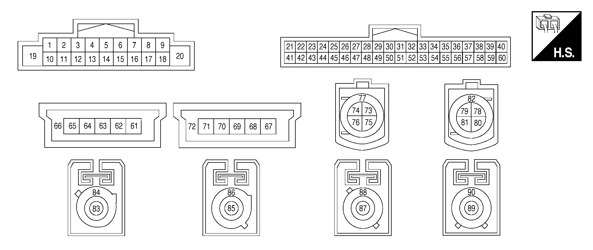
PHYSICAL VALUES
Without Bose Audio System
|
Terminal (Wire color) | Description | Condition |
Reference value (Approx.) | |||
|---|---|---|---|---|---|---|
| + | – | Signal name | Input/Output | Ignition switch | Operation | |
|
2 (W) |
3 (B) |
Front door speaker and instrument panel tweeter sound signal LH | Output | ON | Sound output |
|
|
4 (R) |
5 (G) |
Rear door speaker sound signal LH | Output | ON | Sound output |
|
|
11 (W) |
12 (B) |
Front door speaker and instrument panel tweeter sound signal RH | Output | ON | Sound output |
|
|
13 (GR) |
14 (BG) |
Rear door speaker sound signal RH | Output | ON | Sound output |
|
|
19 (L) |
Ground | Battery power supply | Input | OFF | — | Battery voltage |
|
20 (B) |
Ground | Ground | — | ON | — | 0 V |
|
21 (SB) |
— | CAN-High | Input/Output | — | — | — |
|
22 (SB) |
— | AV communication high | Input/Output | — | — | — |
|
23 (SB) |
— | AV communication high | Input/Output | — | — | — |
|
28 (R) |
Ground | Camera power supply | Output | ON | Camera image displayed | 6.0 V |
| Except for above | 0 V | |||||
|
29 (B) |
Ground | Camera ground | — | ON | — | 0 V |
|
311 (Shield) |
— | Telematics microphone signal shield | — | — | — | — |
|
321 (W) |
521 (B) |
Telematics microphone signal | Input | ON | While speaking into microphone. |
|
|
39 (B) |
Ground | Mic VCC | Output | ON | — | 5.0 V |
|
40 (B)1 (W)2 |
59 (Shield) |
Microphone signal | Input | ON | While speaking into microphone. |
|
|
41 (V) |
— | CAN-Low | Input/Output | — | — | — |
|
42 (LG) |
— | AV communication low | Input/Output | — | — | — |
|
43 (LG) |
— | AV communication low | Input/Output | — | — | — |
|
49 (W) |
48 (Shield) |
Camera image signal | Input | ON | Camera image displayed |
|
|
51 (BG) |
— | HF/VR mode change | — | — | — | — |
|
61 (B) |
— | USB ground | — | — | — | — |
|
63 (G) |
— | USB D+ signal | — | — | — | — |
|
64 (W) |
— | USB D− signal | — | — | — | — |
|
65 (R) |
— | V BUS signal | — | — | — | — |
|
66 (Shield) |
— | USB shield | — | — | — | — |
|
671 (B) |
— | USB ground | — | — | — | — |
|
691 (G) |
— | USB D+ signal | — | — | — | — |
|
701 (W) |
— | USB D− signal | — | — | — | — |
|
711 (R) |
— | V BUS signal | — | — | — | — |
|
721 (Shield) |
— | USB shield | — | — | — | — |
|
75 (G) |
— | Ethernet − | — | — | — | — |
|
76 (Y) |
— | Ethernet + | — | — | — | — |
|
77 (Shield) |
— | Ethernet shield | — | — | — | — |
|
78 (R) |
— | LVDS − | — | — | — | — |
|
81 (L) |
— | LVDS + | — | — | — | — |
|
82 (Shield) |
— | LVDS shield | — | — | — | — |
|
83 (B) |
Ground | AM/FM antenna signal | Input | ON | AV control unit ON, FM-AM selected. | 5.0 V |
|
84 (Shield) |
— | AM/FM antenna shield | — | — | — | — |
|
85 (B) |
Ground | Satellite antenna signal | Input | ON | AV control unit ON, XM selected. | 5.0 V |
|
86 (Shield) |
— | Satellite antenna shield | — | — | — | — |
|
87 (B) |
Ground | GPS antenna signal | Input | ON | AV control unit ON, NAV selected. | 5.0 V |
|
88 (Shield) |
— | GPS antenna shield | — | — | — | — |
|
893 (B) |
Ground | FM sub antenna signal | Input | ON | AV control unit ON, FM-AM selected. | 5.0 V |
|
903 (Shield) |
— | FM sub antenna shield | — | — | — | — |


1: With telematics system
2: Without telematics system
3: For Mexico
With Bose Audio System
|
Terminal (Wire color) | Description | Condition |
Reference value (Approx.) | |||
|---|---|---|---|---|---|---|
| + | – | Signal name | Input/Output | Ignition switch | Operation | |
|
2 (W) |
3 (B) |
Pre-amp sound signal LH | Output | ON | Sound output |
|
|
4 (W) |
5 (B) |
Guide signal | Output | ON | Sound output |
|
|
10 (Shield) |
— | Pre-amp sound signal shield | — | — | — | — |
|
11 (B) |
12 (W) |
Pre-amp sound signal RH | Output | ON | Sound output |
|
|
19 (L) |
Ground | Battery power supply | Input | OFF | — | Battery voltage |
|
20 (B) |
Ground | Ground | — | ON | — | 0 V |
|
21 (SB) |
— | CAN-High | Input/Output | — | — | — |
|
22 (SB) |
— | AV communication high | Input/Output | — | — | — |
|
23 (LA/SB) |
— | AV communication high | Input/Output | — | — | — |
|
31 (Shield) |
— | Telematics microphone signal shield | — | — | — | — |
|
32 (W) |
52 (B) |
Telematics microphone signal | Input | ON | While speaking into microphone. |
|
|
40 (B) |
59 (Shield) |
Microphone signal | Input | ON | While speaking into microphone. |
|
|
41 (V) |
— | CAN-Low | Input/Output | — | — | — |
|
42 (LG) |
— | AV communication low | Input/Output | — | — | — |
|
43 (LA/LG) |
— | AV communication low | Input/Output | — | — | — |
|
51 (BG) |
— | HF/VR mode change | — | — | — | — |
|
61 (B) |
— | USB ground | — | — | — | — |
|
63 (G) |
— | USB D+ signal | — | — | — | — |
|
64 (W) |
— | USB D− signal | — | — | — | — |
|
65 (R) |
— | V BUS signal | — | — | — | — |
|
66 (Shield) |
— | USB shield | — | — | — | — |
|
67 (B) |
— | USB ground | — | — | — | — |
|
69 (G) |
— | USB D+ signal | — | — | — | — |
|
70 (W) |
— | USB D− signal | — | — | — | — |
|
71 (R) |
— | V BUS signal | — | — | — | — |
|
72 (Shield) |
— | USB shield | — | — | — | — |
|
75 (R) |
— | Ethernet − | — | — | — | — |
|
76 (L) |
— | Ethernet + | — | — | — | — |
|
77 (Shield) |
— | Ethernet shield | — | — | — | — |
|
78 (R) |
— | LVDS − | — | — | — | — |
|
81 (L) |
— | LVDS + | — | — | — | — |
|
82 (Shield) |
— | LVDS shield | — | — | — | — |
|
83 (B) |
Ground | AM/FM antenna signal | Input | ON | AV control unit ON, FM-AM selected. | 5.0 V |
|
84 (Shield) |
— | AM/FM antenna shield | — | — | — | — |
|
85 (B) |
Ground | Satellite antenna signal | Input | ON | AV control unit ON, XM selected. | 5.0 V |
|
86 (Shield) |
— | Satellite antenna shield | — | — | — | — |
|
87 (B) |
Ground | GPS antenna signal | Input | ON | AV control unit ON, NAV selected. | 5.0 V |
|
88 (Shield) |
— | GPS antenna shield | — | — | — | — |
|
891 (B) |
Ground | FM sub antenna signal | Input | ON | AV control unit ON, FM-AM selected. | 5.0 V |
|
901 (Shield) |
— | FM sub antenna shield | — | — | — | — |


1: For Mexico
Fail-safe
| DTC | AV control unit operation in fail-safe mode |
|---|---|
| B1305-04 | AV control unit internal error |
| B1309-11 | No sound from Bose speaker amp. |
| B1309-12 | |
| B130B-11 | Rear door speaker RH inoperative |
| B130B-12 | |
| B130B-13 | |
| B130B-1C | |
| B130D-11 |
|
| B130D-12 | |
| B130D-13 | Front door speaker RH inoperative |
| B130D-1C |
|
| B130F-11 |
|
| B130F-12 | |
| B130F-13 | Front door speaker LH inoperative |
| B130F-1C |
|
| B1311-11 | Rear door speaker LH inoperative |
| B1311-12 | |
| B1311-13 | |
| B1311-1C | |
| B1315-11 | No AM/FM radio reception |
| B1315-13 | |
| B1316-11 | No FM radio reception |
| B1316-13 | |
| B1317-11 | No satellite radio reception |
| B1317-13 | |
| B1321-13 | Instrument panel tweeter RH inoperative |
| B1322-13 | Instrument panel tweeter LH inoperative |
| B1328-12 | Microphone is inoperative |
| B1328-13 | |
| B132A-01 | USB is inoperative |
| B132A-13 | |
| B132A-49 | |
| B132C-01 | Telematics system inoperative |
| B132C-13 | |
| B132C-49 | |
| B1339-8F | Rear view camera is inoperative |
| B133A-8F | Camera image is inoperative |
| B133C-02 | Bose speaker amp. is inoperative |
| B1341-16 | Battery protection shuts audio unit down 60 seconds after low voltage condition |
| B1341-17 |
|
| B1341-49 | AV control unit internal failure |
| B1341-55 | AV control unit configuration error |
| B1341-98 | Audio unit shuts down after 5 seconds |
| B1342-62 | Audio and visual system features are unavailable |
| B1343-41 | AV control unit ROM error |
| B1344-41 | AV control unit EEPROM error |
| B1345-49 | AV control unit gyro error |
| B1346-11 | Nissan Pathfinder Vehicle positions of navigation screen differ. |
| B1346-13 | |
| B1346-49 | |
| B1347-49 | Bluetooth® function inoperative |
| B1351-4B | AV control unit shuts down and cannot restart for more than 5 minutes |
| B1356-49 | AV control unit DSP error |
| B135E-49 | AV control unit fan error |
| B1360-02 | Steering switch is inoperative |
| B1375-11 | Rear view camera is inoperative |
| B1375-12 | |
| B1375-13 | |
| B1380-49 | Wi-fi function is inoperative |
| B1383-01 | Predictive course line is not displayed |
| B13CF-73 | AV control unit buttons error |
| B13D9-8F | USB devices connected to front auxiliary input jacks are inoperative |
| B13DA-8F | Intelligent around view monitor display is inoperative |
| B13E5-8F | Telematics system inoperative |
| U0079-00 | CAN communication does not function |
| U1000-01 | Function of CAN communication signals received by AV control unit are inoperative |
| U1300-01 | AV communication is inoperative |
| U2118-87 | The system using the CAN communication signal from control unit which cannot communicate does not function. |
| U2143-87 | |
| U2148-87 | |
| U214E-87 | |
| U214F-87 | |
| U215B-87 | |
| U2164-87 | |
| U2165-87 | |
| U216B-87 | |
| U2175-87 | |
| U2176-87 | |
| U2177-87 | |
| U224E-87 | |
| U226D-87 | |
| U2754-88 | ― |
DTC Inspection Priority Chart
If multiple DTCs are detected simultaneously, check them one by one depending on the following DTC inspection priority chart.
| Priority | Detected items (DTC) |
|---|---|
| 1 |
|
| 2 |
|
| 3 |
|
DTC Index
| CONSULT Display | Reference Page |
|---|---|
| B1305-04: Control unit internal fault | DTC Description |
| B1309-11: AV control unit | DTC Description |
| B1309-12: AV control unit | |
| B130B-11: Rear RH speaker | DTC Description |
| B130B-12: Rear RH speaker | |
| B130B-13: Rear RH speaker | |
| B130B-1C: Rear RH speaker | |
| B130D-11: Front RH speaker | DTC Description |
| B130D-12: Front RH speaker | |
| B130D-13: Front RH speaker | |
| B130D-1C: Front RH speaker | |
| B130F-11: Front LH speaker | DTC Description |
| B130F-12: Front LH speaker | |
| B130F-13: Front LH speaker | |
| B130F-1C: Front LH speaker | |
| B1311–11: Rear LH speaker | DTC Description |
| B1311–12: Rear LH speaker | |
| B1311–13: Rear LH speaker | |
| B1311–1C: Rear LH speaker | |
| B1315–11: AM/FM 1 antenna | DTC Description |
| B1315–13: AM/FM 1 antenna | |
| B1316–11: FM 2 antenna | DTC Description |
| B1316–13: FM 2 antenna | |
| B1317–11: XM antenna connection | DTC Description |
| B1317–13: XM antenna connection | |
| B1321-13: Front RH tweeter | DTC Description |
| B1322-13: Front LH tweeter | DTC Description |
| B1328-12: External microphone 1 | DTC Description |
| B1328-13: External microphone 1 | |
| B132A-01: External USB | DTC Description |
| B132A-13: External USB | |
| B132A-49: External USB | |
| B132C-01: TCU connection | DTC Description |
| B132C-13: TCU connection | |
| B132C-49: TCU connection | |
| B1339–8F: Rear camera | DTC Description |
| B133A–8F: Around view monitor | DTC Description |
| B133C–02: Amplifier | DTC Description |
| B1341–16: Head unit | DTC Description |
| B1341–17: Head unit | |
| B1341–49: Head unit | |
| B1341–55: Head unit | |
| B1341–98: Head unit | |
| B1342–62: Locked system | DTC Description |
| B1343–41: ECU Rom | DTC Description |
| B1344–41: ECU EEPROM | DTC Description |
| B1345–49: ECU Gyro | DTC Description |
| B1346–11: GPS antenna connection | DTC Description |
| B1346–13: GPS antenna connection | |
| B1346–49: GPS antenna connection | |
| B1347–49: Bluetooth module | DTC Description |
| B1351–4B: AV control unit | DTC Description |
| B1356–49: ECU DSP | DTC Description |
| B135E–49: AV control unit | DTC Description |
| B1360–02: Combination meter | DTC Description |
| B1375–11: Rear camera | DTC Description |
| B1375–12: Rear camera | |
| B1375–13: Rear camera | |
| B1380–49: Wi-Fi module | DTC Description |
| B1383–01: Steering angle sensor | DTC Description |
| B13CF-73: Control switch | DTC Description |
| B13D9–8F: USB communication | DTC Description |
| B13DA-8F: LVDS | DTC Description |
| B13E5–8F: TCU connection | DTC Description |
| U0079–00: Control module comm Bus G Off | DTC Description |
| U1000–01: CAN COMM CIRCUIT | DTC Description |
| U1300–01: AV communication circuit | DTC Description |
| U2118-87: CAN comm err (Intelligent Key) | DTC Description |
| U2143-87: CAN comm err (VCM/HCM) | DTC Description |
| U2148-87: CAN comm err (brake control unit) | DTC Description |
| U214E-87: CAN comm err (combination meter) | DTC Description |
| U214F-87: CAN comm err (BCM) | DTC Description |
| U215B-87: CAN comm err (IPDM E/R) | DTC Description |
| U2164-87: CAN comm err (DPC/driver seat) | DTC Description |
| U2165-87: CAN comm err (sonar) | DTC Description |
| U216B-87: CAN comm err (front camera) | DTC Description |
| U2175-87: CAN comm err (AVM) | DTC Description |
| U2176-87: CAN comm err (CCM) | DTC Description |
| U2177-87: CAN comm err (passenger seat) | DTC Description |
| U224E-87: CAN comm err (combination meter) | DTC Description |
| U226D-87: CAN comm err (TCU) | DTC Description |
| U2754-88: Ethernet circuit | DTC Description |
Bose Speaker Amp. Nissan Pathfinder SUV
Values On The Diagnosis Tool
 NOTE:
NOTE:
The following table includes information (items) inapplicable to this Nissan Pathfinder vehicle. For information (items) applicable to this vehicle, refer to CONSULT display items.
| Monitor Item | Condition | Value/Status | |
|---|---|---|---|
| ENGINE SPEED |
This item is display, but not monitored. |
||
| Nissan Pathfinder Vehicle speed | During vehicle driving | Input value of Nissan Pathfinder vehicle speed signal | |
| DOOR STATUS |
This item is display, but not monitored. |
||
 NOTE:
NOTE:
 NOTE:
NOTE:
Reference Value
TERMINAL LAYOUT
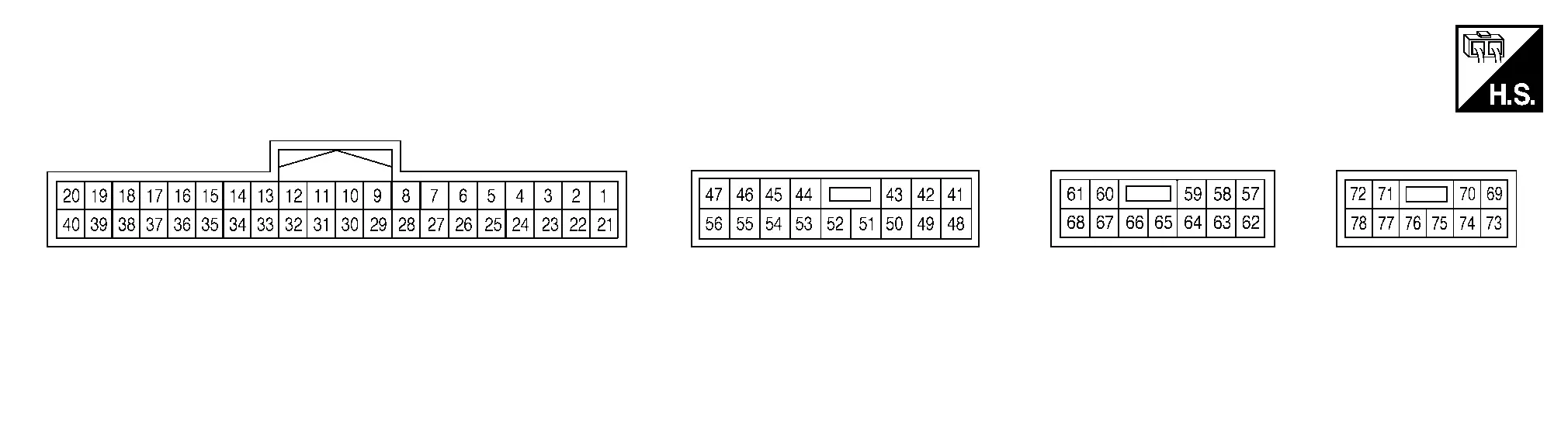
PHYSICAL VALUES
|
Terminal (Wire color) | Description | Condition |
Reference value (Approx.) | ||
|---|---|---|---|---|---|
| + | – | Signal name | Input/Output | ||
|
1 (V) |
21 (LG) |
Sound signal LH | Output |
Ignition switch ON
|
|
|
2 (W) |
22 (B) |
Sound signal RH | Input |
Ignition switch ON
|
|
|
3 (L) |
23 (R) |
Guide signal | Input |
Ignition switch ON
|
|
|
10 (LA/SB) |
— | CAN-High | Input/Output | — | — |
|
11 (LA/V) |
— | CAN-Low | Input/Output | — | — |
|
13 (LA/LG) |
— | AV communication high | Input/Output | — | — |
|
14 (LA/SB) |
— | AV communication low | Input/Output | — | — |
|
41 (G) |
48 (V) |
Sound signal rear door speaker LH | Output |
Ignition switch ON
|
|
|
42 (W) |
49 (P) |
Sound signal rear door speaker RH | Output |
Ignition switch ON
|
|
|
43 (L) |
50 (GR) |
Sound signal instrument panel tweeter LH | Output |
Ignition switch ON
|
|
|
44 (SB) |
53 (BR) |
Sound signal rear side speaker LH | Output |
Ignition switch ON
|
|
|
45 (LG) |
54 (R) |
Sound signal rear side speaker RH | Output |
Ignition switch ON
|
|
|
46 (P) |
55 (Y) |
Sound signal center speaker | Output |
Ignition switch ON
|
|
|
51 (BG) |
52 (W) |
Sound signal instrument panel tweeter RH | Output |
Ignition switch ON
|
|
|
57 (LG) |
62 (GR) |
Battery power supply | — | Ignition switch OFF | Battery voltage |
|
58 (SB) |
63 (GR) |
Battery power supply | — | Ignition switch OFF | Battery voltage |
|
59 (R) |
64 (GR) |
Battery power supply | — | Ignition switch OFF | Battery voltage |
|
60 (W) |
67 (B) |
Sound signal front door speaker and front tweeter RH | Output |
Ignition switch ON
|
|
|
61 (Y) |
68 (L) |
Sound signal subwoofer 1 | Output |
Ignition switch ON
|
|
|
62 (GR) |
— | Ground | — | Ignition switch ON | 0 V |
|
63 (GR) |
— | Ground | — | Ignition switch ON | 0 V |
|
64 (GR) |
— | Ground | — | Ignition switch ON | 0 V |
|
65 (G) |
66 (BR) |
Sound signal front door speaker and front tweeter LH | Output |
Ignition switch ON
|
|
|
69 (LG) |
73 (BG) |
Sound signal subwoofer 2 | Output |
Ignition switch ON
|
|


Fail-safe
| DTC | Bose speaker amp. operation in fail-safe mode |
|---|---|
| B1A01–11 |
|
| B1A01–12 | |
| B1A01–13 | Front door speaker LH is inoperative. |
| B1A01–1A |
|
| B1A05–11 |
|
| B1A05–12 | |
| B1A05–13 | Front door speaker RH is inoperative. |
| B1A05–1A |
|
| B1A0A–11 | Instrument panel tweeter LH is inoperative. |
| B1A0A–12 | |
| B1A0A–13 | |
| B1A0A–1A | |
| B1A0E–11 | Center speaker is inoperative. |
| B1A0E–12 | |
| B1A0E–13 | |
| B1A0E–1A | |
| B1A12–11 | Instrument panel tweeter RH is inoperative. |
| B1A12–12 | |
| B1A12–13 | |
| B1A12–1A | |
| B1A2F–13 | Front tweeter LH is inoperative. |
| B1A33–13 | Front tweeter RH is inoperative. |
| B1A4C–11 | Rear door speaker LH is inoperative. |
| B1A4C–12 | |
| B1A4C–13 | |
| B1A4C–1A | |
| B1A50–11 | Rear door speaker RH is inoperative. |
| B1A50–12 | |
| B1A50–13 | |
| B1A50–1A | |
| B1A62–11 | Rear side speaker LH is inoperative. |
| B1A62–12 | |
| B1A62–13 | |
| B1A62–1A | |
| B1A66–11 | Rear side speaker RH is inoperative. |
| B1A66–12 | |
| B1A66–13 | |
| B1A66–1A | |
| B1A69–11 | Subwoofer 1 is inoperative. |
| B1A69–12 | |
| B1A69–13 | |
| B1A69–1A | |
| B1A71–11 | Subwoofer 2 is inoperative. |
| B1A71–12 | |
| B1A71–13 | |
| B1A71–1A | |
| B1A80–49 | Bose speaker amp. is inoperative. |
| B1A80–4B | |
| B1A80–55 | |
| U0079–00 | CAN communication does not function. |
| U2140–87 | All self-diagnosis functions are inoperative. |
| U2148–87 | |
| U214E–87 | |
| U214F–87 | |
| U215B–87 |
DTC Inspection Priority Chart
If multiple DTCs are detected simultaneously, check them one by one depending on the following DTC inspection priority chart:
| Priority | Detected items (DTC) |
|---|---|
| 1 |
|
| 2 |
|
| 3 |
|
DTC Index
| CONSULT Display | Refererence Page |
|---|---|
| B1A01-11: Front left door woofer out | DTC Description |
| B1A01-12: Front left door woofer out | |
| B1A01-13: Front left door woofer out | |
| B1A01-1A: Front left door woofer out | |
| B1A05-11: Front right door woofer out | DTC Description |
| B1A05-12: Front right door woofer out | |
| B1A05-13: Front right door woofer out | |
| B1A05-1A: Front right door woofer out | |
| B1A0A-11: Front instrument left squawker out | DTC Description |
| B1A0A-12: Front instrument left squawker out | |
| B1A0A-13: Front instrument left squawker out | |
| B1A0A-1A: Front instrument left squawker out | |
| B1A0E-11: Front instrument center squawker out | DTC Description |
| B1A0E-12: Front instrument center squawker out | |
| B1A0E-13: Front instrument center squawker out | |
| B1A0E-1A: Front instrument center squawker out | |
| B1A12-11: Front instrument right squawker out | DTC Description |
| B1A12-12: Front instrument right squawker out | |
| B1A12-13: Front instrument right squawker out | |
| B1A12-1A: Front instrument right squawker out | |
| B1A2F-13: Front left pillar tweeter out | DTC Description |
| B1A33-13: Front right pillar tweeter out | DTC Description |
| B1A4C-11: RL-DOOR speaker OUT | DTC Description |
| B1A4C-12: RL-DOOR speaker OUT | |
| B1A4C-13: RL-DOOR speaker OUT | |
| B1A4C-1A: RL-DOOR speaker OUT | |
| B1A50-11: RR-DOOR speaker OUT | DTC Description |
| B1A50-12: RR-DOOR speaker OUT | |
| B1A50-13: RR-DOOR speaker OUT | |
| B1A50-1A: RR-DOOR speaker OUT | |
| B1A62-11: RL-PILLAR squawker OUT | DTC Description |
| B1A62-12: RL-PILLAR squawker OUT | |
| B1A62-13: RL-PILLAR squawker OUT | |
| B1A62-1A: RL-PILLAR squawker OUT | |
| B1A66-11: RR-PILLAR squawker OUT | DTC Description |
| B1A66-12: RR-PILLAR squawker OUT | |
| B1A66-13: RR-PILLAR squawker OUT | |
| B1A66-1A: RR-PILLAR squawker OUT | |
| B1A69-11: Rear luggage left woofer out | DTC Description |
| B1A69-12: Rear luggage left woofer out | |
| B1A69-13: Rear luggage left woofer out | |
| B1A69-1A: Rear luggage left woofer out | |
| B1A71-11: Rear luggage right woofer out | DTC Description |
| B1A71-12: Rear luggage right woofer out | |
| B1A71-13: Rear luggage right woofer out | |
| B1A71-1A: Rear luggage right woofer out | |
| B1A80-49: ANC UNIT | DTC Description |
| B1A80-4B: ANC UNIT | |
| B1A80-55: ANC UNIT | |
| U0079-00: Control module comm bus G off | DTC Description |
| U2140-87: CAN comm err (ECM) | DTC Description |
| U2148-87: CAN comm err (brake control unit) | DTC Description |
| U214E-87: CAN comm err (combination meter) | DTC Description |
| U214F-87: CAN comm err (BCM) | DTC Description |
| U215B-87: CAN comm err (IPDM E/R) | DTC Description |

Nissan Pathfinder (R53) 2022-2026 Service Manual
Ecu Diagnosis Information
Contact Us
Nissan Pathfinder Info Center
Email: info@nipathfinder.com
Phone: +1 (800) 123-4567
Address: 123 Pathfinder Blvd, Nashville, TN 37214, USA
Working Hours: Mon–Fri, 9:00 AM – 5:00 PM (EST)
