Nissan Pathfinder: Audio, Visual & Navigation System - System Description
Component Parts Nissan Pathfinder Fifth generation
Intelligent Around View Monitor System
Component Parts Location
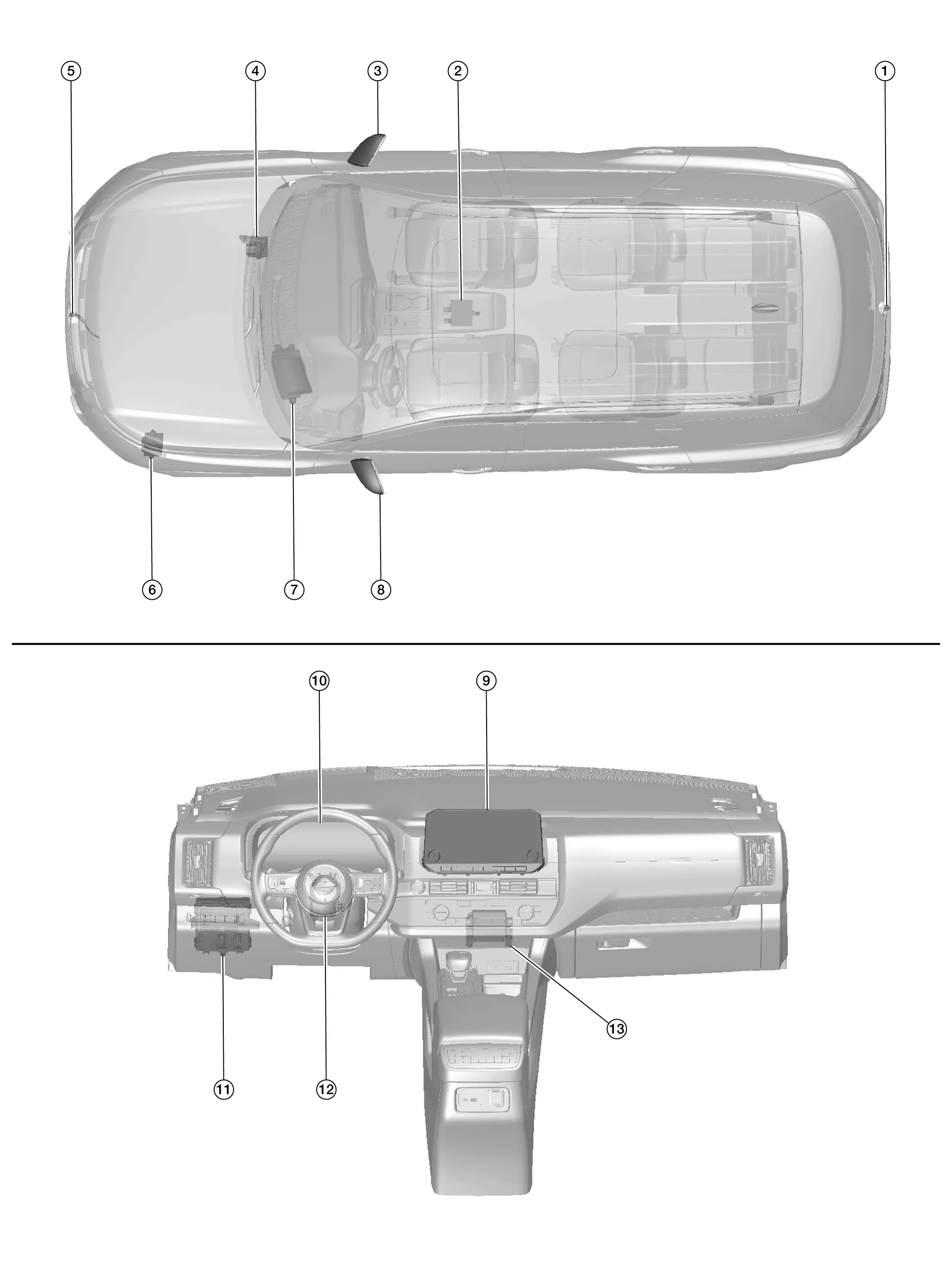
| No. | Component | Function |
|---|---|---|
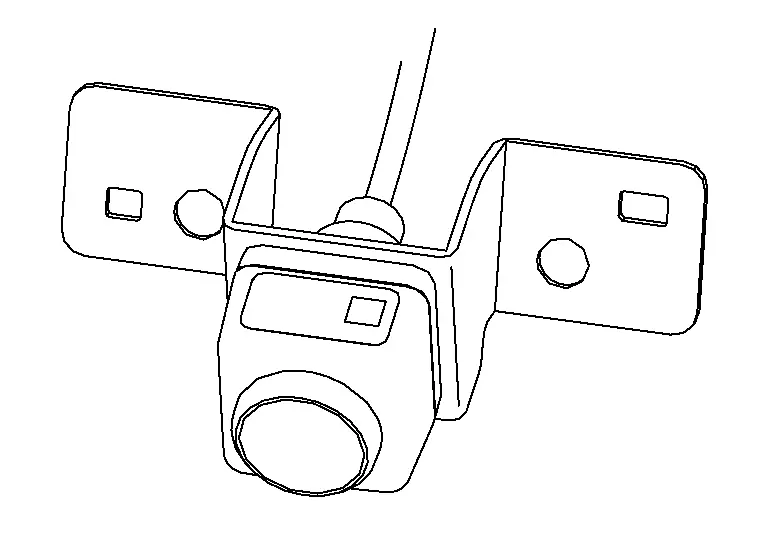
| 1. | Rear camera | Refer to Rear Camera. |
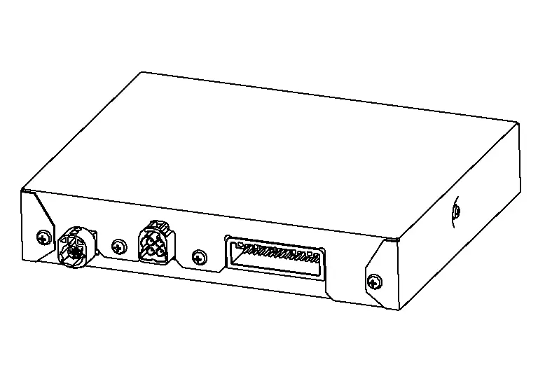
| 2. | Around view monitor control unit | Refer to Around View Monitor Control Unit. |
| 3. | Side camera RH | Refer to Side Camera. |
| 4. | ABS (Anti-lock Braking System) actuator and electric unit (control unit) |
Provides around view monitor control unit with the following signals via CAN communication:
|
| 5. | Front camera | Refer to Front Camera. |
| 6. | TCM (Transmission Control Module) |
Provides around view monitor control unit with the shift position signal via CAN communication. Refer to Component Parts Location for detailed component location. |
| 7. | Head up display unit (if so equipped) |
Provides AV control unit with the head up information signals via AV communication. Refer to Component Parts Location (full TFT meter) or Component Parts Location (7 inch information display meter) for detailed component location. |
| 8. | Side camera LH | Refer to Side Camera. |
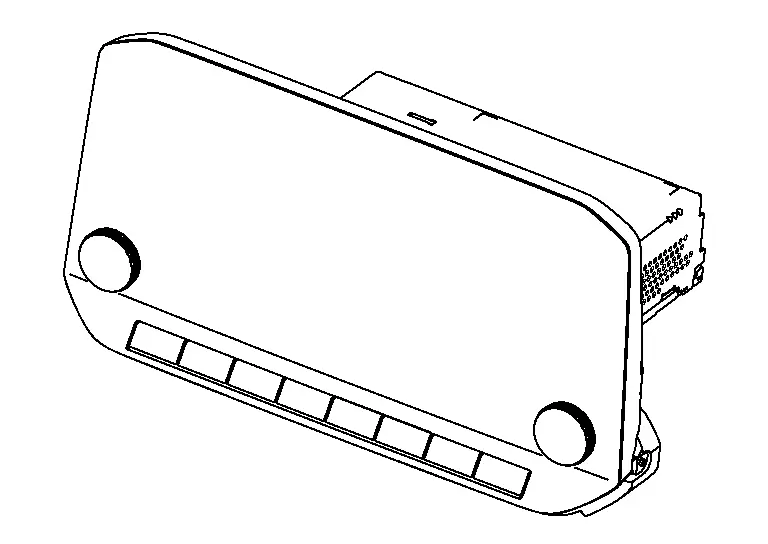
| 9. | AV control unit | Refer to AV Control Unit. |
| 10. | Combination meter |
|
| 11. | BCM (Body Control Module) |
Provides around view monitor control unit with the door switch signals via CAN communication. Refer to System Description. |
| 12. | Steering angle sensor | Refer to Steering Angle Sensor. |
| 13. | Sonar control unit |
Provides around view monitor control unit with the sonar indicator signal via CAN communication. Refer to Component Parts Location for detailed component location. |
AV Control Unit
-
An 8-inch (without navigation) or 9-inch (with navigation) color display with multi-touch control, an AM/FM electronic tuner radio with RDS and camera controller are integrated into the AV Control unit.
-
The color display is a high resolution monitor that includes touch panel functions.
Around View Monitor Control Unit
-
The around view monitor control unit is installed under the center console.
-
Necessary signals are transmitted/received to/from control unit via CAN communication.
-
Camera image signals received from each camera are converted/synthesized in the around view monitor control unit and transmitted to the AV control unit via LVDS.
 NOTE:
NOTE:
-
LVDS (Low Voltage Differential Signaling) is a differential signaling system.
-
It transmits information through the difference between the voltages on a pair of wires.
-
The two wire differences are compared at the receiving module.
-
-
Nissan Pathfinder Vehicle width guide lines, predicted course line, vehicle front guiding line and vehicle side line, tire icon, and Nissan Pathfinder vehicle icon are rendered with the around view monitor control unit and combined with camera image.
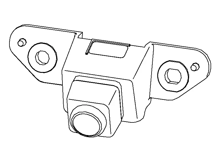
Front Camera
-
The front camera is installed in the front grille.
-
Image at the front of the Nissan Pathfinder vehicle is sent to the around view monitor control unit via LVDS.
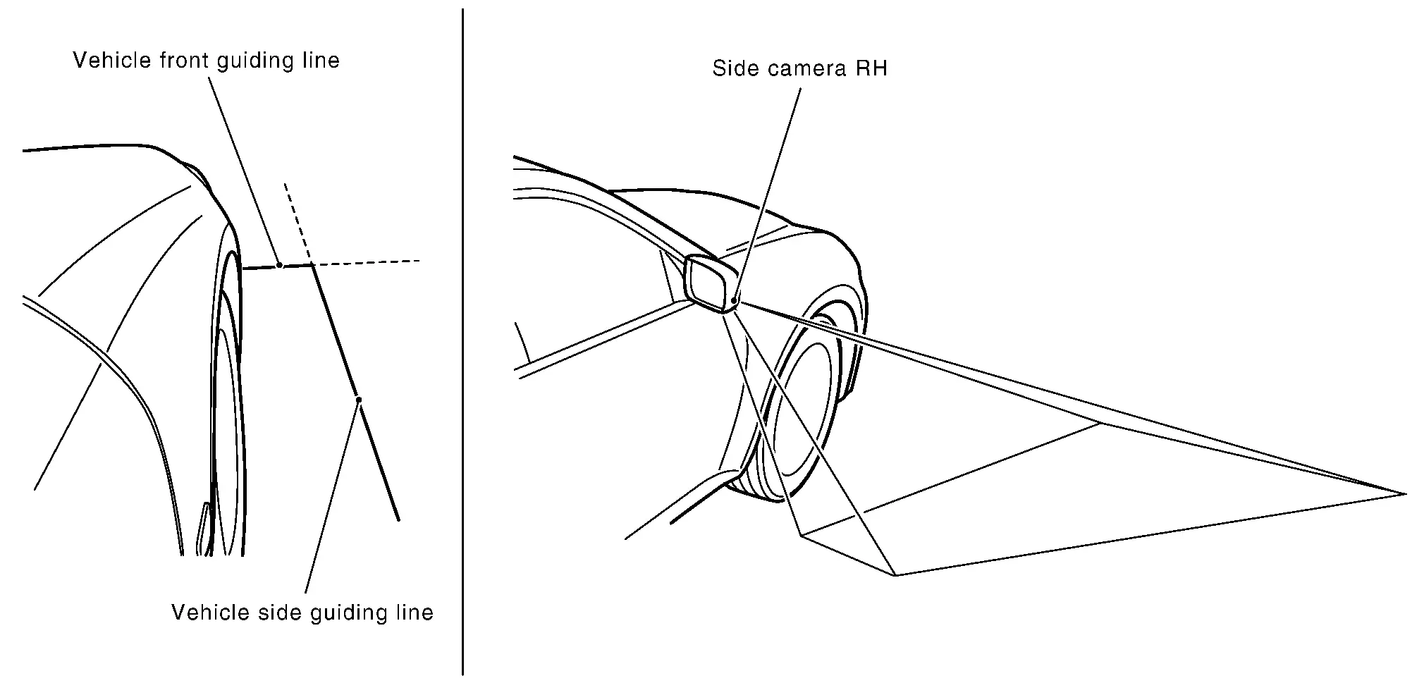
Side Camera
-
The side camera is installed in the door mirror.
-
Images at the sides of the Nissan Pathfinder vehicle are sent to the around view monitor control unit via LVDS.
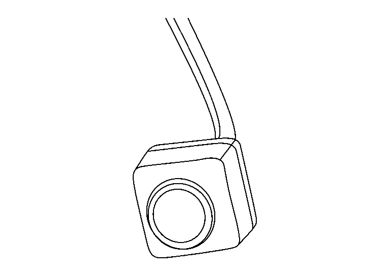
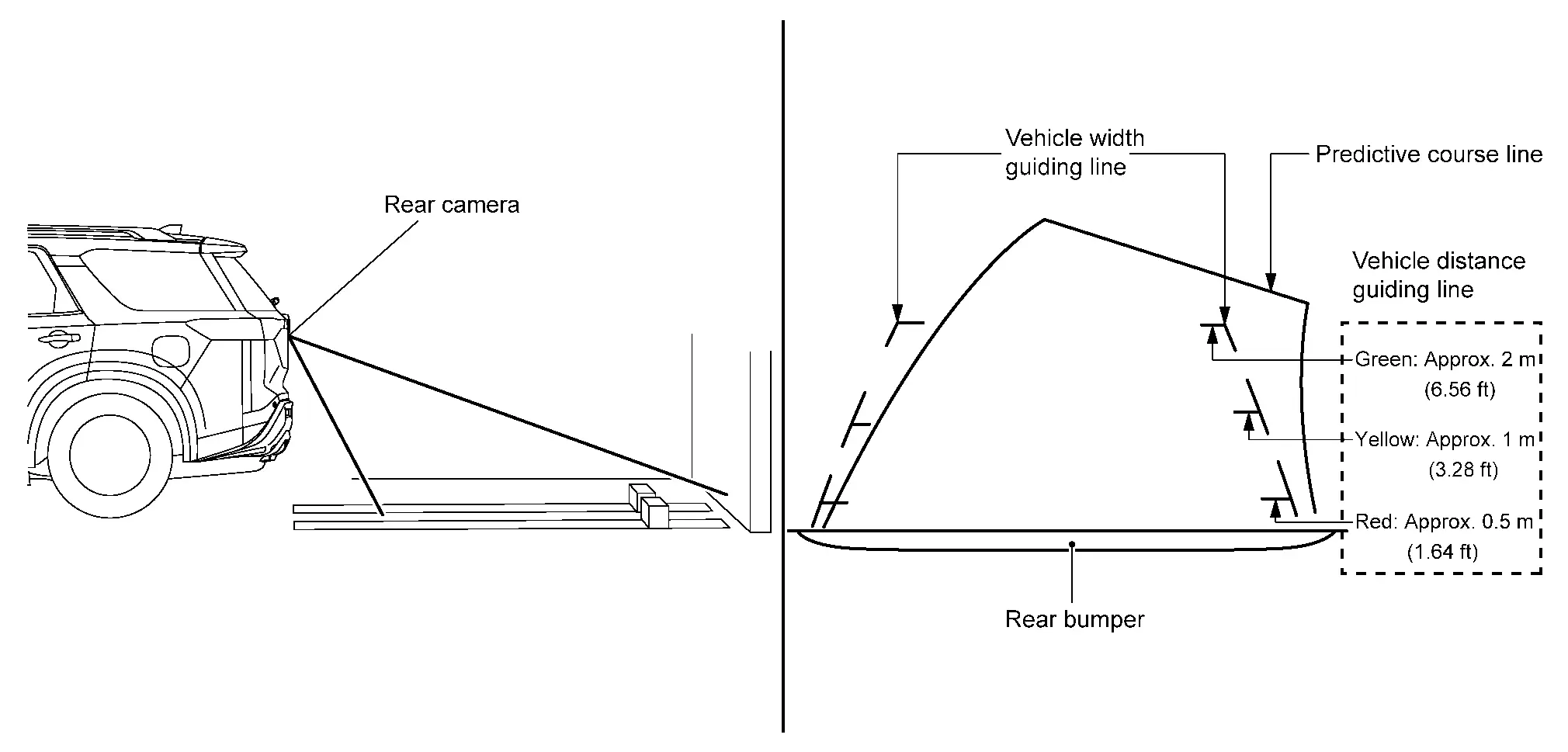
Rear Camera
-
The rear view camera is installed at the center of the back door finisher.
-
Image at the rear of the Nissan Pathfinder vehicle is sent to the around view monitor control unit via LVDS.
Steering Angle Sensor
-
Steering angle sensor is installed to the combination switch (spiral cable).
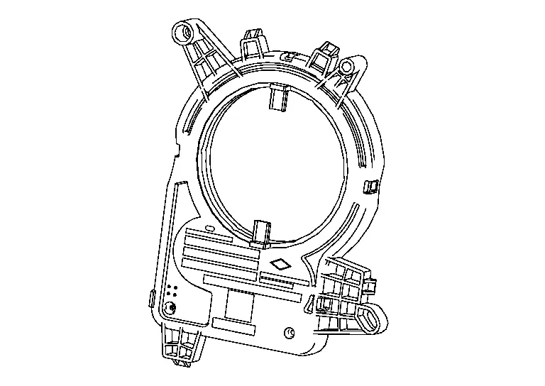
-
Steering angle sends the steering signal necessary for predictive course line of the front or rear view monitor to the around view monitor control unit via CAN communication.
System Nissan Pathfinder R53
System Description
SYSTEM DIAGRAM
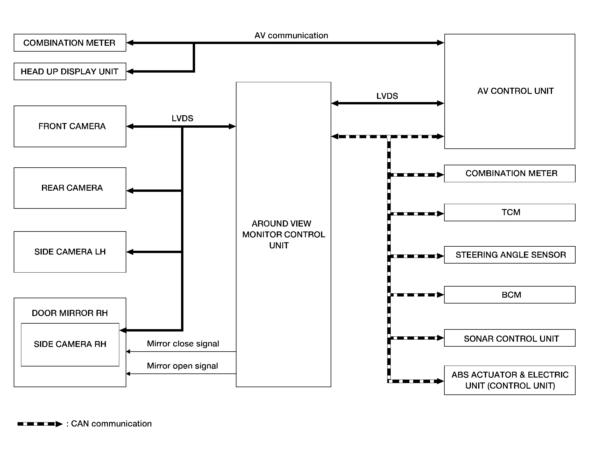
Around View Monitor Control Unit Input Signal (CAN Communication)
| Transmit unit | Signal name |
|---|---|
| ABS actuator and electric unit (control unit) | Nissan Pathfinder Vehicle speed signal |
| Wheel speed signals | |
| BCM | Door switch signals |
| AV control unit | Camera switch signal |
| Combination meter | MOD setting signal |
| Sonar control unit | Sonar indicator signal |
| TCM | Shift position signal |
AV Control Unit Input Signal (AV Communication)
| Transmit unit | Signal name |
|---|---|
| Combination meter | Steering switch signal |
| Head up display unit | Head up information signals |
AV Control Unit Input Signal (CAN Communication)
| Transmit unit | Signal name |
|---|---|
| Combination meter |
|
DESCRIPTION
-
This system is equipped with wide-angle high-resolution cameras on the front and rear of the Nissan Pathfinder vehicle and on both right and left door mirrors. The images from front view, rear view, front-side view passenger side, and birds-eye view that shows the view from the top of the Nissan Pathfinder vehicle are displayed to monitor the vehicle surroundings.
-
Around view monitor control unit cuts out and expands the image received from each camera to create each view.
-
The sonar indicator is displayed on display (superimposed on the camera image) in combination with the sonar system to warm of the approach of an obstacle.
-
Camera image is displayed on the display when an obstacle is detected by sonar system.
-
In front view and rear view, the Nissan Pathfinder vehicle width, distance lines and predictive course lines are superimposed and displayed. In front-side view, the Nissan Pathfinder vehicle distance guiding line and vehicle width guiding line are displayed.
-
The Birds-Eye view converts the images from 4 cameras into the overhead view and displays the status of the Nissan Pathfinder vehicle on display. The vehicle icon and sonar indicator that are displayed on the Birds-Eye view display are rendered by around view monitor control unit.
-
Moving Object Detection (MOD) is adopted that detects moving objects according to camera image and notifies the detection result to the driver.
-
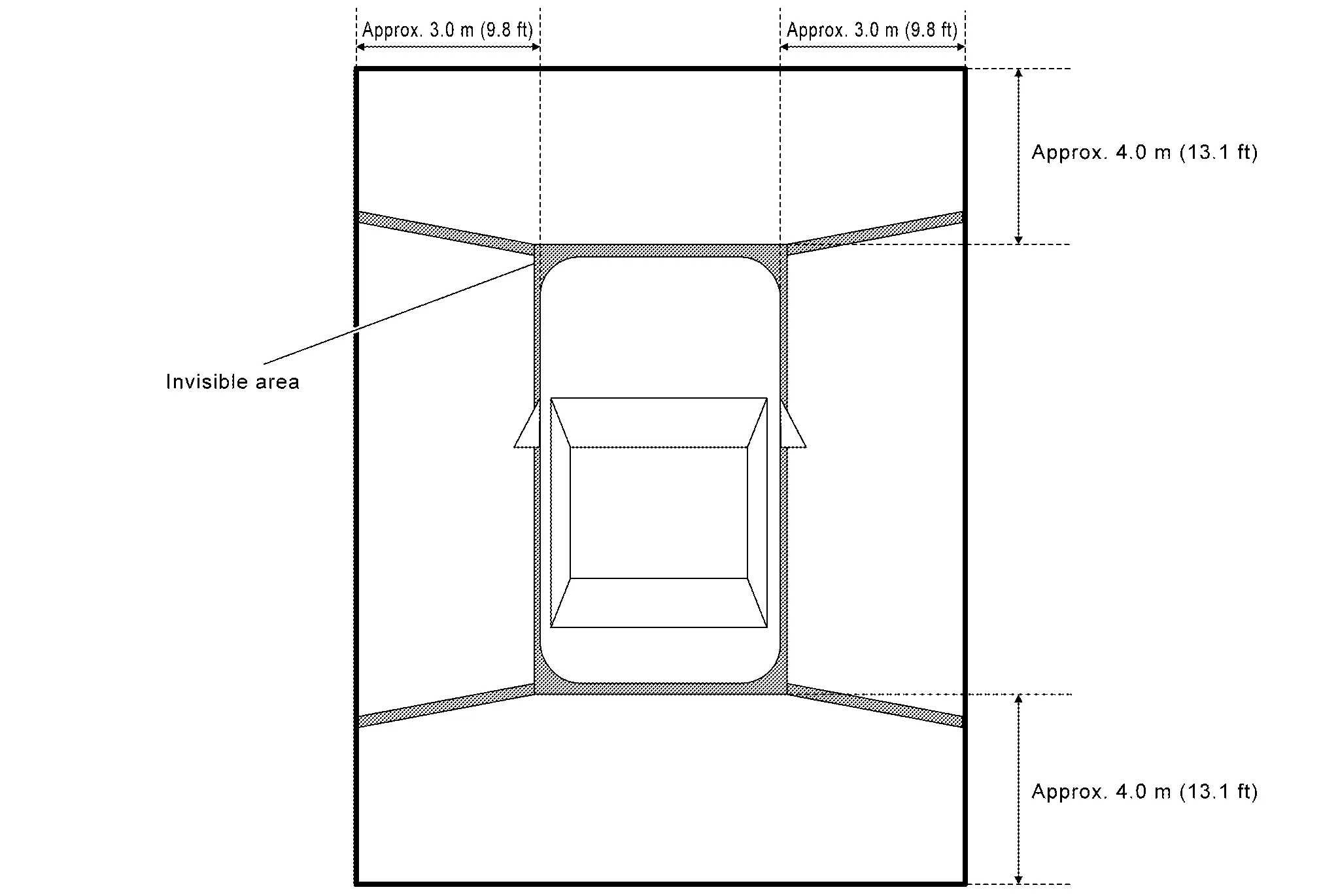
Front/rear wide view function is adopted. Visibility for the left and right that contains invisible area is improved.
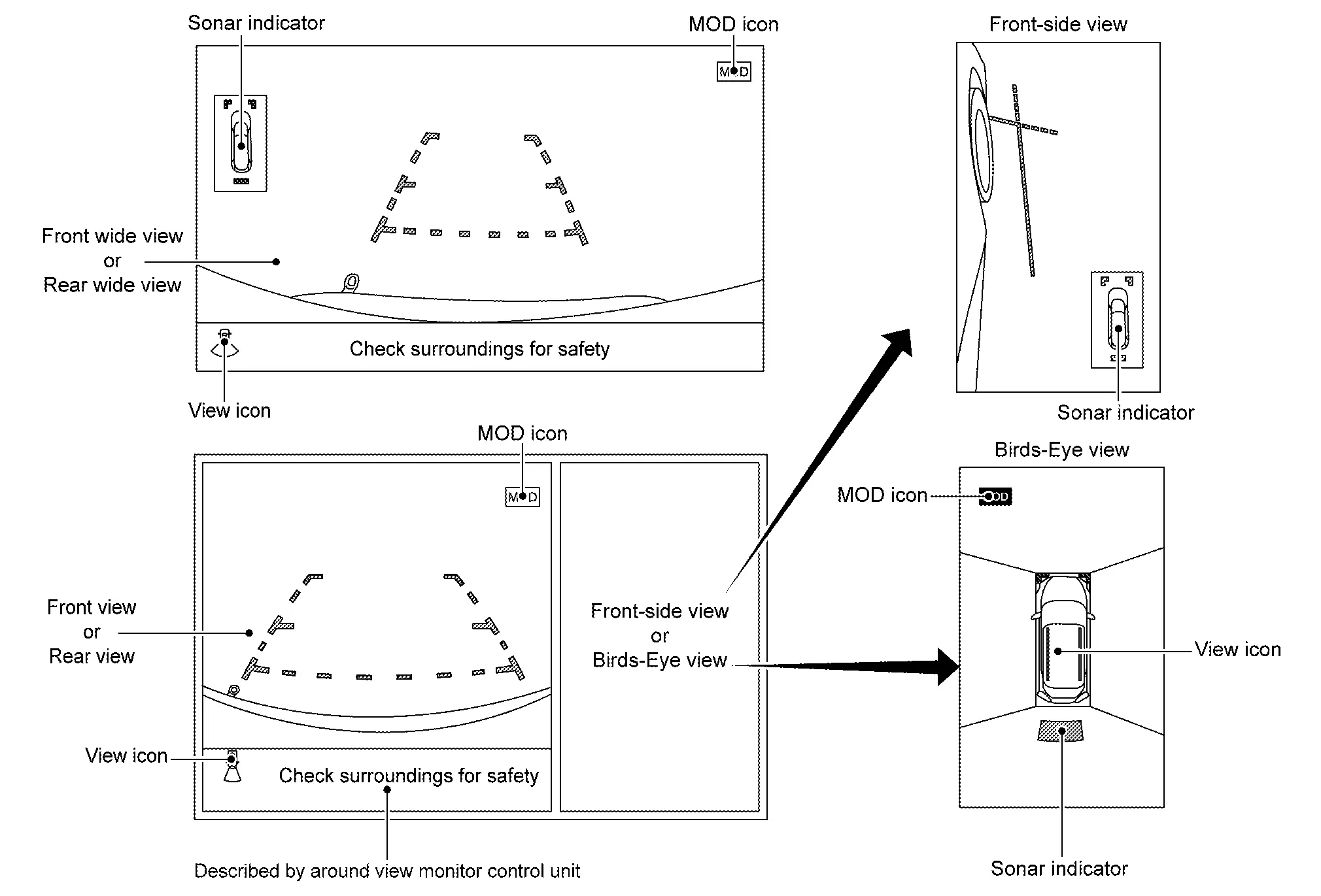
AROUND VIEW MONITOR SCREEN
-
Around view monitor combines and displays the travel direction view and “Birds-Eye view”, “Front-Side view” and then it displays the sonar indicator on the “Birds-Eye view”, “Front-Side view”, "Front wide view" and “Rear wide view”.
-
Around view monitor control unit renders the view icon, warning message on display.
Screen Constitution (Models with Invisible Area)
Screen Constitution (Models without Invisible Area)
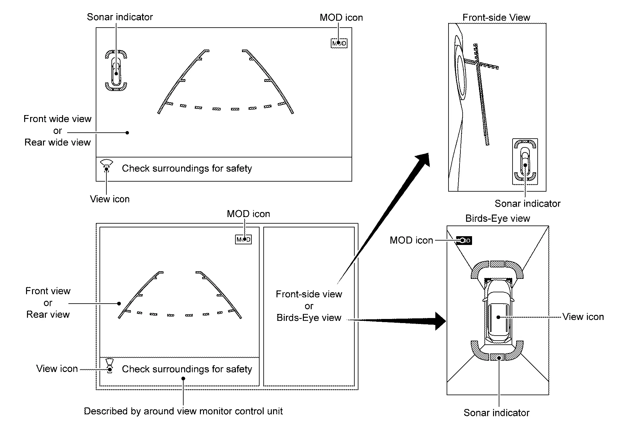
 NOTE:
NOTE:
The presence or absence of the invisible area depends on the sonar specifications.
OPERATION DESCRIPTION
Around view monitor screen transition
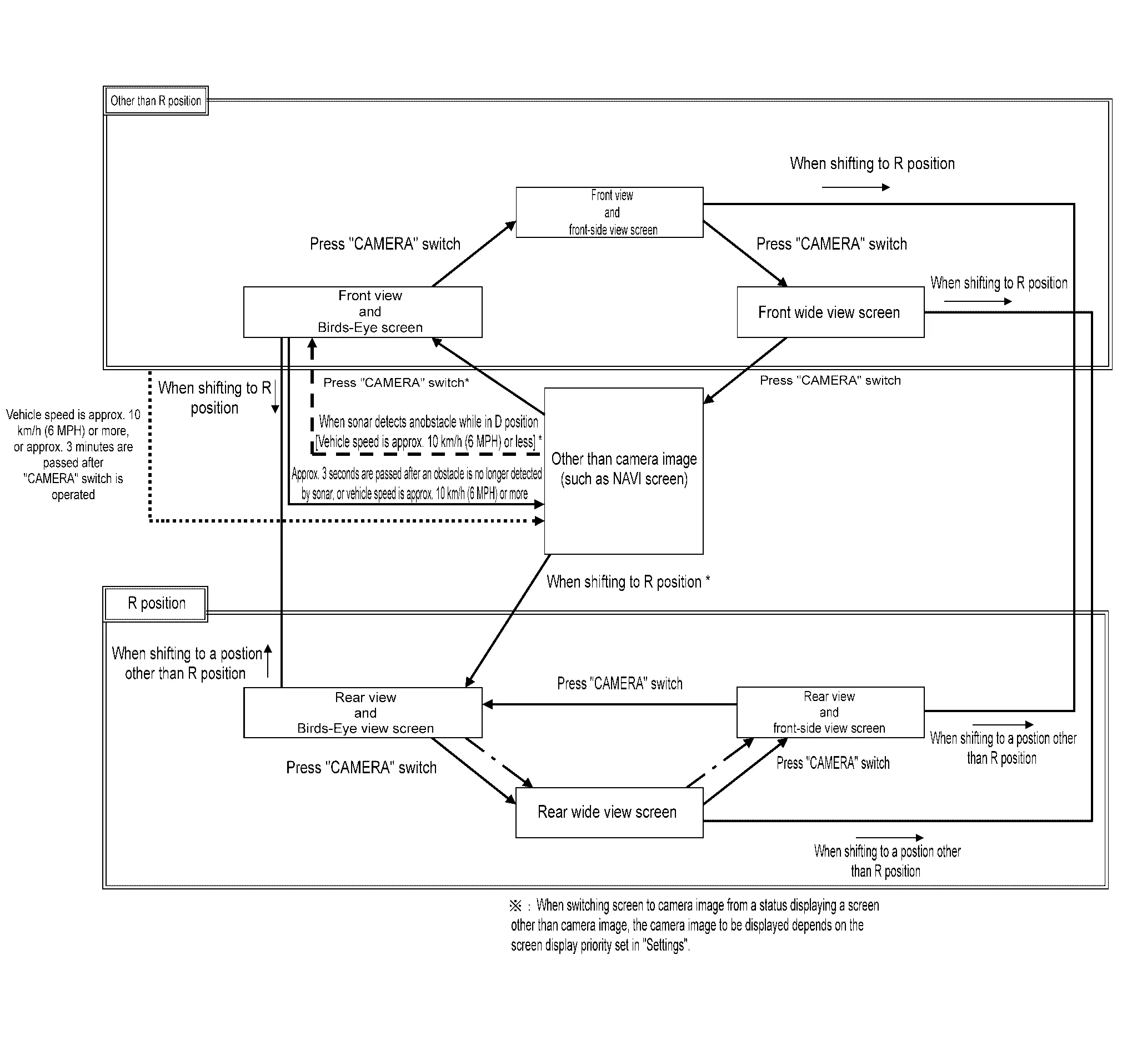
-
Around view monitor is displayed on the display when “CAMERA” switch is pressed, when shifting position is reverse, or when an obstacle is detected by sonar system.
-
Birds-Eye view, Front-side view, and front/rear wide view can be switched by “CAMERA” switch, while around view monitor is displayed.
-
While shift position is other than reverse, around view monitor is cancelled when approximately 3 minutes are passed after “CAMERA” switch is pressed, or when Nissan Pathfinder vehicle speed is approximately 10 km/h (6 MPH) or more. The screen returns to the screen before displaying around view monitor.
-
Setting of Moving Object Detection (MOD) and sonar can be switched ON/OFF by combination meter.
-
In Birds-Eye view, an enhanced boundary is displayed on the image indicating the invisible area and clearly indicating the boundary of the 4 cameras. The invisible area is displayed in yellow when Birds-Eye view is displayed after the ignition switch is turned ON. (Models with invisible area)
-
In D position, front sonar can detect an obstacle while camera image is not displayed on AV control unit. Screen is switched to camera image when an obstacle is detected.
-
When “CAMERA” switch is pressed, it receives camera switch signal from AV control unit via CAN communication.
-
When around view monitor control unit receives camera switch signal, around view monitor control unit reads the image signal from each camera.
-
When around view monitor control unit receives reverse signal, while shift position is R position, around view monitor control unit reads image signal from each camera by LVDS.
-
When around view monitor control unit reads image signal from each camera, it cuts out the required screen for each view, superimposes camera image, Nissan Pathfinder vehicle icon, guiding lines, predicted course line, “MOD” icon, and sonar indicator, and then outputs them to AV control unit by LVDS.
Front View
-
The front view image is from the front camera.
-
When the selector lever is in any position other than the reverse position, the front view is displayed by pressing the “CAMERA” switch. It improves the visibility of obstacles in front of the Nissan Pathfinder vehicle and helps driving by the images displayed from Birds-Eye view and Front-Side view. The front wide view function allows the display of an image with an approximately 180° horizontal angle.
-
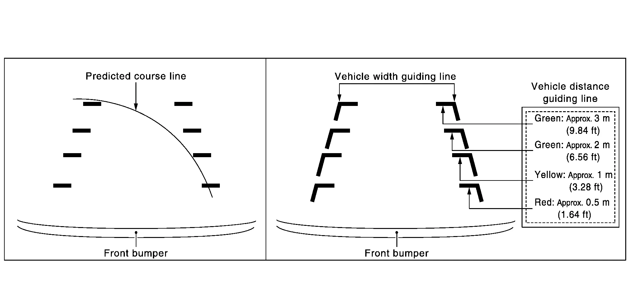
Display the Nissan Pathfinder vehicle width guiding line and vehicle distance guiding line in front view and display the predictive course line according to the steering angle.
-
If the steering angle is within approximately 90 degrees, the predictive course lines on the left/right side are displayed. If the steering angle is exceeding approximately 90 degrees, only the predictive course line on the outside (in the opposite side of steering direction) is displayed.
-
Around view monitor control unit receives the steering angle signal from ABS actuator and electric unit (control unit) via CAN communication.
-
Around view monitor control unit controls the direction of the predictive course line according to the steering sensor angle signal.
Front view guiding lines
Rear View
-
The rear view image is from the rear camera.
-
When the selector lever is in the reverse position, the rear view is displayed. Backing and parking are improved by the images from Birds-Eye view and Front-Side view. The rear wide view function allows the display of an image with an approximately 180° horizontal angle.
-
Display the Nissan Pathfinder vehicle width guiding line and vehicle distance guiding line in rear view and display the predictive course line according to the steering angle.
-
The predictive course line is not displayed at the steering neutral position.
-
Around view monitor control unit receives the steering angle signal from ABS actuator and electric unit (control unit) via CAN communication.
-
Around view monitor control unit controls the direction and distance of predictive course line according to the steering angle sensor signal.
Rear view guiding lines
Front-side View
-
The front-side view image is from the side camera RH.
-
In front-side view, display the Nissan Pathfinder vehicle distance guiding line and vehicle width guiding line.
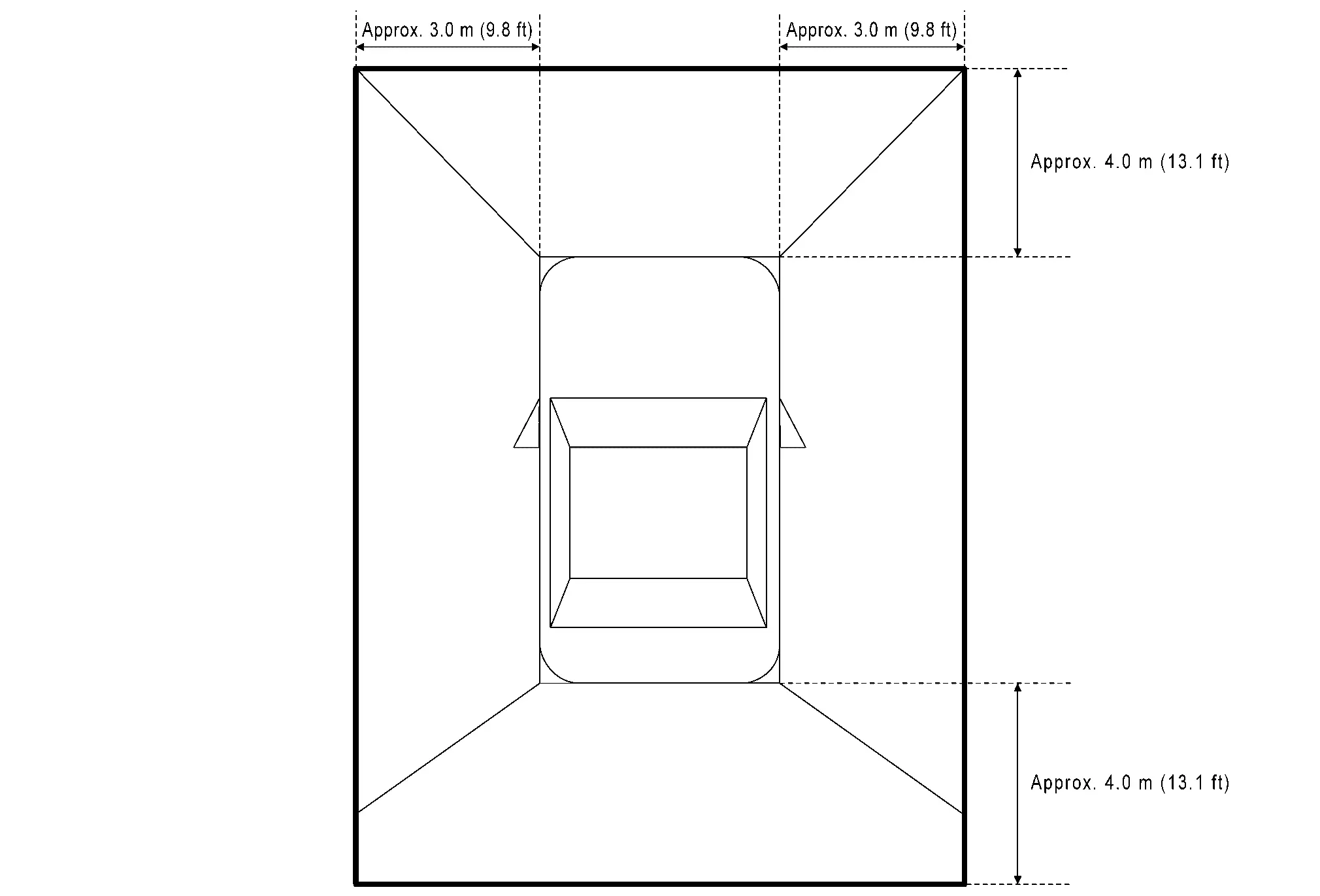
Front-side view area and guiding line
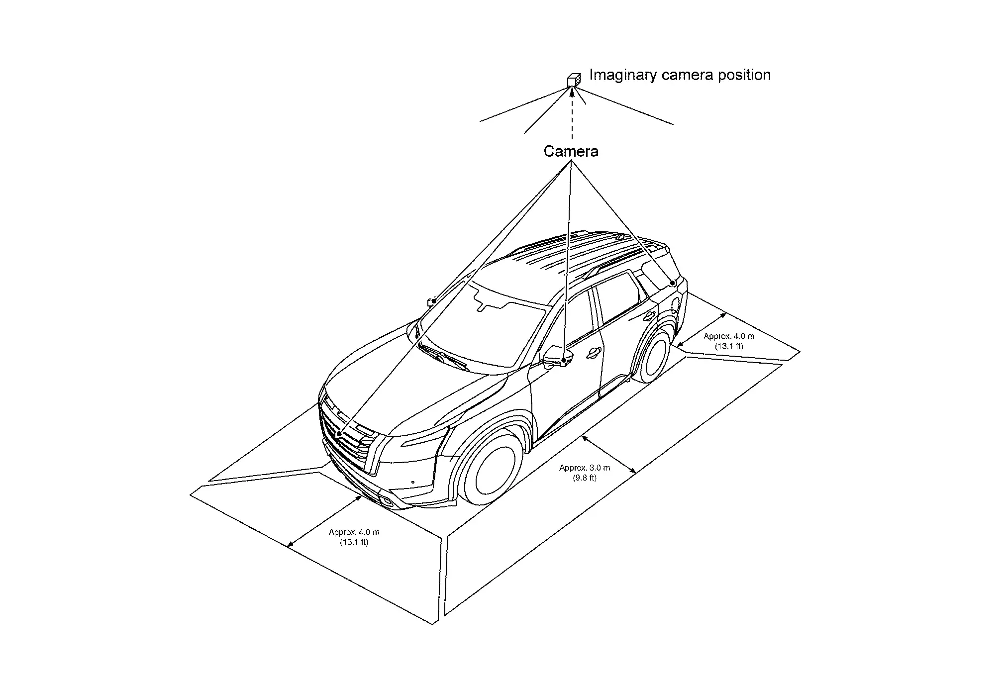
Birds-eye View
-
The image from the 4 cameras is cut out and converted into the overhead view, and the surroundings of the Nissan Pathfinder vehicle is displayed in birds-eye view.
-
In Birds-Eye view, the invisible area is displayed on the image to specify the boundary of the 4 cameras. (Models with invisible area)
Birds-Eye view display image
Birds-Eye view display area (Models with Invisible Area)
Birds-Eye view display area (Models without Invisible Area)
Moving Object Detection (MOD)
-
Moving Object Detection (MOD) is a function that notifies the driver of the presence of moving objects in the area around the Nissan Pathfinder vehicle. MOD detects moving objects from camera image, illuminates frame of view in yellow whenever “MOD” icon is displayed in green, and sounds buzzer.
-
MOD detects moving objects while camera image is displayed on AV control unit.
-
Around view monitor control unit performs the following process when moving objects are detected.
-
Superimposes yellow frame line on camera image signal and outputs them to AV control unit by LVDS.
-
Transmits MOD beep sound output request signal to combination meter via CAN communication.
-
Combination meter that receives the MOD beep sound output request signal from around view monitor control unit, and outputs buzzer drive signal to buzzer.
-
-
Around view monitor control unit detects moving objects from camera image according to an image recognition method called optical flow.
-
MOD does not detect a background as a moving object when the Nissan Pathfinder vehicle moves (when whole screen moves), but detects a moving object when an actual moving object is displayed on screen.
-
MOD can be set to permanent OFF by the following operation.
-
Permanent OFF: Settings can be performed on the information display of the combination meter.
-
-
Color of “MOD” icon indicates whether or not MOD is operative. “MOD” icon is displayed as shown in the following table. when MOD is operative, “MOD” icon is displayed in green. when MOD is not operative, “MOD” icon is displayed in gray. MOD icon is not displayed when MOD is OFF by “Settings”.
View Shift position P or N position D position R position “MOD” icon display Birds-Eye view and rear view Birds-Eye view — — Gray Rear view Green Birds-Eye view and front view Birds-Eye view Green Gray — Front view Gray Green Side view and rear view Side view — — × Rear view Green Side view and front view Side view × × — Front view Gray Green Rear wide view — — Green Front wide view Gray Green — ×: Icon is not displayed.
—: View is not displayed in each shift position (P or N position, D position and R position).
-
MOD illuminates frame of view in yellow and sounds buzzer, when any of the conditions in the following table are satisfied.
Operation Condition View where MOD is operative Shift position Nissan Pathfinder Vehicle speed P or N position 0 km/h (0 MPH) Birds-Eye view D position 0 km/h (0 MPH) or more - less than 8 km/h (5 MPH) -
Front view
-
Front wide view
R position 0 km/h (0 MPH) or more - less than 8 km/h (5 MPH) -
Rear view
-
Rear wide view
-
-
MOD does not operate or stops operation when any of the conditions in the following table are satisfied.
Operation stop condition Note Door open -
MOD does not stop operation for front view and front wide view.
-
Operation stops for rear view and rear wide view while back door is open.
-
Operation stops for Birds-Eye view when any door is open.
Door mirror expanding/retracting Expanding/retracting status of door mirror is judged according to operation signal of door mirror motor transmitted from door mirror (driver side) to around view monitor control unit. -
CAMERA ASSISTANCE SONAR FUNCTION
-
Sonar sensors are installed on front and rear bumpers. When an obstacle is detected while Intelligent Around View Monitor is displayed, a sonar indicator display and buzzer sound notify the driver of the proximity of an obstacle. When an obstacle is detected while Intelligent Around View Monitor is not displayed, Intelligent Around View Monitor screen is displayed automatically, and then notification is similar as while Intelligent Around View Monitor is displayed.
-
Approaching distance between bumper and obstacle is displayed in 3 stages according to the color of the sonar indicator in display and blinking cycle of indicator.
-
Warning by buzzer sound notifies distance to obstacle according to a 3-stage cycle.
MAC(Message Authentication Code)
MAC (Message Authentication Code) is a function that prevents unauthorized communication from other than the ECU with MAC function by secure authentication communication. Around view monitor control unit can write a MAC key required for communication between the ECUs and perform MAC diagnosis.
Diagnosis System (around View Monitor Control Unit) Nissan Pathfinder 2022
CONSULT Function
CONSULT FUNCTIONS
CONSULT performs the following functions via the communication with the around view monitor control unit.
| Diagnosis mode | Description |
|---|---|
| Self Diagnostic Result | Around view monitor control unit and AV communication circuit connection diagnosis is performed. Current and previous malfunctions are displayed collectively. |
| Data Monitor | Diagnosis of Nissan Pathfinder vehicle signal that is received by around view monitor control unit can be performed. |
| Work support |
|
| ECU Identification | Around view monitor control unit part number, software version, and hardware version can be identified. |
| Configuration* | Writes the Nissan Pathfinder vehicle specification when replacing around view monitor control unit. |
| MAC Diagnosis* |
Display MAC diagnosis result divided into the following two inspection priorities.
|
*: Displays when performing "Diagnosis (All System)".
SELF DIAGNOSTIC RESULT
Refer to DTC Index.
-
In CONSULT self-diagnosis, self-diagnosis results and error history are displayed collectively.
-
The current malfunction indicates “CRNT”. The past malfunction indicates “PAST”.
Freeze Frame Data (FFD)
The following vehicle status is recorded when DTC is detected and is displayed on CONSULT.
| Item name [Unit] | Display content |
|---|---|
|
ODO/TRIP METER [km] |
Total driving distance (odometer value) upon DTC detection is displayed. |
DATA MONITOR
 NOTE:
NOTE:
The following table includes information (items) inapplicable to this Nissan Pathfinder vehicle. For information (items) applicable to this vehicle, refer to CONSULT display items.
-
Displays the status of the following vehicle signals inputted into the around view monitor control unit.
-
For each signal, actual signal can be compared with the condition recognized on the system.
Display Item Remarks REVERSE SIGNAL
[On/Off]Receiving status of shift position (reverse) signal received from TCM is displayed by ON/OFF. CAMERA SWITCH SIGNAL
[On/Off]Receiving status of camera switch signal received from AV control unit is displayed by ON/OFF. CAMERA OFF SIGNAL
[On/Off]Receiving status of camera OFF signal received from AVcontrol unit is displayed by ON/OFF. REAR CAMERA IMAGE SIGNAL
[OK/NG]Input status of rear view camera image signal is displayed by OK/NG in real time. R-CAMERA COMM STATUS
[OK/NG]Communication status with rear camera is displayed by OK/NG in real time. R-CAMERA COMM LINE
[OK/NG]Status of communication line with rear camera is displayed by OK/NG in real time. F-CAMERA IMAGE SIGNAL
[OK/NG]Input status of front view camera image signal is displayed by OK/NG in real time. F-CAMERA COMM STATUS
[OK/NG]Communication status with front camera is displayed by OK/NG in real time. F-CAMERA COMM LINE
[OK/NG]Status of communication line with front camera is displayed by OK/NG in real time. Left camera image signal
[OK/NG]Input status of side camera LH image signal is displayed by OK/NG in real time. Left camera comm status
[OK/NG]Communication status with side camera LH is displayed by OK/NG in real time. Left camera line
[OK/NG]Status of communication line with side camera LH is displayed by OK/NG in real time. Right camera image signal
[OK/NG]Input status of side camera RH image signal is displayed by OK/NG in real time. Right camera comm status
[OK/NG]Communication status with side camera RH is displayed by OK/NG in real time. Right camera line
[OK/NG]Status of communication line with side camera RH is displayed by OK/NG in real time. FOLDING MOTOR VOLT 1
[On/Off]Receiving status of mirror fold position (open) signal received from door mirror RH is displayed by ON/OFF. FOLDING MOTOR VOLT 2
[On/Off]Receiving status of mirror fold position (close) signal received from door mirror RH is displayed by ON/OFF. Image output
[On/Off]Display the image signal transmission status by ON / OFF in real time. Power supply state Display the value of around view monitor control unit power supply. Nissan Pathfinder Vehicle speed
[KPH]Display the value of vehicle speed signal.
WORK SUPPORT
| Work support items | Description |
|---|---|
| MAC KEY writing | Write MAC key to around view monitor control unit. |
| PREDICTIVE COURSE LINE DISPLAY |
This item display, but not use. |
| tire diameter correction |
This item display, but not use. |
| MOD function | Select ON/OFF for MOD function. |
| INITIALIZE CAMERA IMAGE CALIBRATION |
The calibration can be initialized to factory shipment condition.
Calibration of camera image caused by misalignment of the camera installation position is performed. |
| CALIBRATING CAMERA IMAGE (FRONT CAMERA) |
Performs the calibration of front camera.
Calibration of camera image caused by misalignment of the camera installation position is performed. |
| CALIBRATING CAMERA IMAGE (PASS-SIDE CAMERA) |
Performs the calibration of side camera RH.
Calibration of camera image caused by misalignment of the camera installation position is performed. |
| CALIBRATING CAMERA IMAGE (DR-SIDE CAMERA) |
Performs the calibration of side camera LH.
Calibration of camera image caused by misalignment of the camera installation position is performed. |
| CALIBRATING CAMERA IMAGE (REAR CAMERA) |
Performs the calibration of rear camera.
Calibration of camera image caused by misalignment of the camera installation position is performed. |
| FINE TUNING OF BIRDS-EYE VIEW |
The confirmation and adjustment of the difference between each camera can be performed. The fine adjustment function of camera calibration can check and adjust the difference between each camera. |
 NOTE:
NOTE:
 NOTE:
NOTE:
 NOTE:
NOTE:
 NOTE:
NOTE:
 NOTE:
NOTE:
 NOTE:
NOTE:
 NOTE:
NOTE:
ECU IDENTIFICATION
Around view monitor control unit part number, software version, and hardware version can be identified.
CONFIGURATION
Writes the vehicle specification when replacing around view monitor control unit.

Nissan Pathfinder (R53) 2022-2026 Service Manual
System Description
Contact Us
Nissan Pathfinder Info Center
Email: info@nipathfinder.com
Phone: +1 (800) 123-4567
Address: 123 Pathfinder Blvd, Nashville, TN 37214, USA
Working Hours: Mon–Fri, 9:00 AM – 5:00 PM (EST)
