Nissan Pathfinder: Audio, Visual & Navigation System - Basic Inspection
- Diagnosis and Repair Workflow
- Additional Service When Replacing Around View Monitor Control Unit
- Mac Key Writing
- Configuration (around View Monitor Control Unit)
- Writing of Calibration Data
- Calibrating Camera Image (intelligent Around View Monitor)
Diagnosis and Repair Workflow Nissan Pathfinder R53
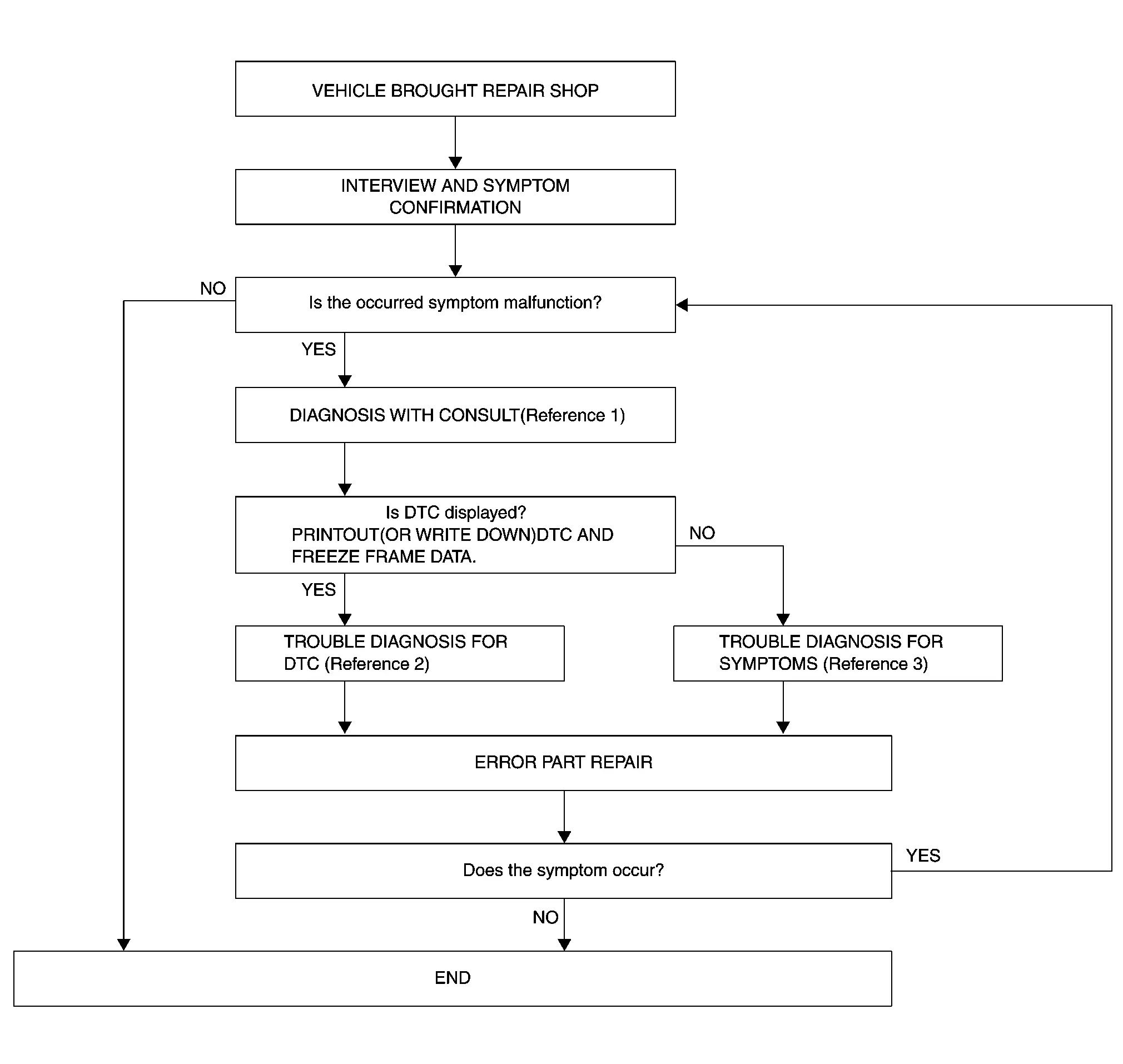
Work Flow
OVERALL SEQUENCE
-
Reference 1: Refer to CONSULT Function.
-
Reference 2: Refer to DTC Index.
-
Reference 3: Refer to Symptom Table.
DETAILED FLOW
INTERVIEW AND SYMPTOM CONFIRMATION
Check the malfunction symptoms by performing the following items:
-
Interview the customer to obtain the malfunction information (conditions and environment when the malfunction occurred).
-
Check the symptom.
Is the occurred symptom a malfunction?
YES>>GO TO 2.
NO>>Inspection End.
DIAGNOSIS WITH CONSULT
 CONSULT
-
Select "Self Diagnostic Result" mode of “AVM”. Refer to CONSULT Function.
 NOTE:
NOTE:
Skip to step 4 of the diagnosis procedure if “AVM” is not displayed.
-
When DTC is detected, Record DTC and Freeze Frame Data (FFD).
Is DTC displayed?
YES>>GO TO 3.
NO>>GO TO 4.
TROUBLE DIAGNOSIS FOR DTC
 CONSULT
-
Check the DTC indicated in the “Self Diagnostic Result”.
-
Perform the relevant diagnosis referring to the DTC Index. Refer to DTC Index.
>>
GO TO 5.
TROUBLE DIAGNOSIS FOR SYMPTOMS
Perform the relevant diagnosis referring to the diagnosis chart by symptom. Refer to Symptom Table.
>>
GO TO 5.
ERROR PART REPAIR
 CONSULT
-
Repair or replace the identified malfunctioning parts.
-
Select "Self Diagnostic Result" mode of “AVM”.
 NOTE:
NOTE:
Erase the stored self-diagnosis results after repairing or replacing the relevant components if any DTC has been indicated in the “Self Diagnostic Result”.
-
Check that the symptom does not occur.
Does the symptom occur?
YES>>GO TO 1.
NO>>Inspection End.
Additional Service When Replacing Around View Monitor Control Unit Nissan Pathfinder 2026
Description
CAUTION:
-
When replacing the around view monitor control unit, always replace it with a new one. Intelligent around view monitor system does not operate properly in case of reuse of the around view monitor control unit from another Nissan Pathfinder vehicle.
-
Always write the MAC key before writing the around view monitor control unit configuration.
Perform the following operations when replacing around view monitor control unit. For details, refer to Work Procedure.
AFTER REPLACEMENT
After replacing around view monitor control unit, the following items must be performed. If not performed, the intelligent around view monitor system will not operate normally:
-
Writing MAC key
-
Configuration
-
Camera calibration
Work Procedure
Perform the following procedures after replacing the around view monitor control unit:
REPLACE AROUND VIEW MONITOR CONTROL UNIT
Replace around view monitor control unit. Refer to Removal and Installation.
>>
GO TO 2.
WRITING MAC KEY
Perform MAC key writing. Refer to Description.
>>
GO TO 3.
PERFORM CONFIGURATION
CAUTION:
Always write the MAC key before writing the around view monitor control unit configuration.
Perform configuration. Refer to Description.
>>
GO TO 4.
WRITING OF CALIBRATION DATA
Write the calibration data stored in the camera. Refer to Work Procedure.
>>
GO TO 5.
PERFORM SELF-DIAGNOSIS
 CONSULT
-
Select "Self Diagnostic Result" mode of "AVM".
-
Check if any DTCs are detected.
Are any DTCs detected?
YES>>Perform the trouble diagnosis for the detected DTC. Refer to DTC Index.
NO>>GO TO 6.
OPERATION CHECK
Confirm that the operation of the intelligent around view monitor and the camera image (reference line, expected route) are normal.
>>
Work End.
Mac Key Writing Nissan Pathfinder Fifth generation
Description
When replacing around view monitor control unit, it is necessary to write MAC key to around view monitor control unit. Write MAC key to around view monitor control unit according to "MAC Key writing" procedure of "CONSULT Operation Manual". Refer to Work Procedure.
CAUTION:
During MAC key writing, maintain the following conditions:
-
Ignition switch ON
-
CONSULT is connected to internet
Work Procedure
PERFORM MAC KEY WRITING
 CONSULT
-
Ignition switch ON.
-
Select "MAC Key writing" in "Work Support" mode of "AVM".
-
Touch "Write".
YES>>
Work End.
Configuration (around View Monitor Control Unit) Nissan Pathfinder
Description
Vehicle specification needs to be written with CONSULT because it is not written after replacing the around view monitor control unit.
The configuration requires network connection. CONSULT connects to network and then it downloads the configuration data from the server. Then CONSULT writes the Nissan Pathfinder vehicle specification to the around view monitor control unit.
Refer to Work Procedure.
 NOTE:
NOTE:
For details on the network connection and operation, refer to “CONSULT Operation Manual”.
The configuration doesn’t need to “save” configuration data from the around view monitor control unit. The configuration data is always generated fresh from the server and then downloaded to the CONSULT.
CAUTION:
-
Complete the procedure of “Configuration” in order.
-
If incorrect “Configuration”, incidents might occur.
Work Procedure
WRITING VEHICLE SPECIFICATION
 CONSULT
Perform writing Nissan Pathfinder vehicle specification to around view monitor control unit following "Automatic Configuration" procedure of "Configuration" according to CONSULT Operation Manual.
 NOTE:
NOTE:
-
Log into the network according to CONSULT instructions.
-
For details on the network connection and operation, refer to “CONSULT Operation Manual”.
>>
Work End.
Writing of Calibration Data Nissan Pathfinder 2022
Work Procedure
WRITE CALIBRATION DATA
 CONSULT
-
Select "CALIBRATING CAMERA IMAGE" in "Work Support" mode of "AVM".
-
Check that the status of each camera is displayed as "Normal".
Is the status of each camera displayed as "Normal"?
YES>>Inspection End
NO>>Calibrate the camera that is not displayed as "normal". Refer to Work Procedure.
Calibrating Camera Image (intelligent Around View Monitor) Nissan Pathfinder 5th Gen
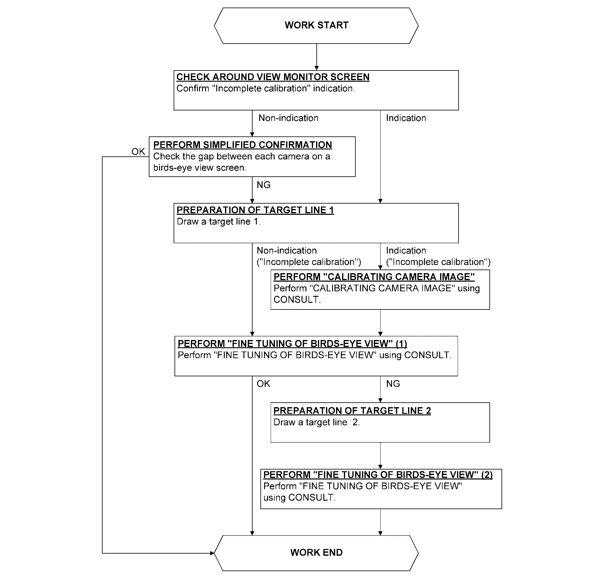
Work Procedure
-
Calibration must be performed after removing/replacing the cameras, removing parts (e.g. front grille, door mirror, and others) mounted on the cameras, or replacing the around view monitor control unit.
-
The use of CONSULT is required to perform calibration or writing of calibration results to the around view monitor control unit.
-
Align the white lines on the road near the Nissan Pathfinder vehicle at the boundary of each camera image by this camera calibration. The white lines far from the vehicle may not be aligned at the boundary of each camera image. The farther the line, the greater the difference is.
-
Following the flowchart shown in the figure, perform the calibration.
CAUTION:
When around view monitor control unit is replaced, Write the calibration data before performing camera image calibration. Refer to Work Procedure.
CHECK AROUND VIEW MONITOR SCREEN
Check that there is no indication of “Incomplete calibration”.
 NOTE:
NOTE:
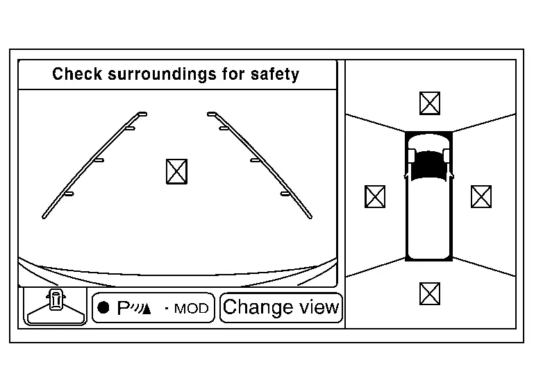
View in the incomplete calibration state is indicated by “
 ” on the around view monitor.
Is the “Incomplete calibration” display visible?
YES>>GO TO 3.
NO>>GO TO 2.
PERFORM SIMPLIFIED CONFIRMATION BY BIRDS-EYE VIEW SCREEN
Check the gap between each camera image on a birds-eye view screen.
Does the gap between each camera image exist?
YES>>GO TO 3.
NO>>Work End.
PREPARATION OF TARGET LINE 1
 NOTE:
NOTE:
-
If a target line is narrow, it is hard to confirm it with around view monitor screen. The width of the target line recommends an approximately 5.0 - 10.0 cm (1.97 - 3.94 in).
-
It is easy to confirm a target line on a around view monitor screen when draw a target line with a color opposite to a working floor.
Example
-
Floor is blue: target line is yellow
-
Floor is green: target line is red
-
Preparation of target line 1
-
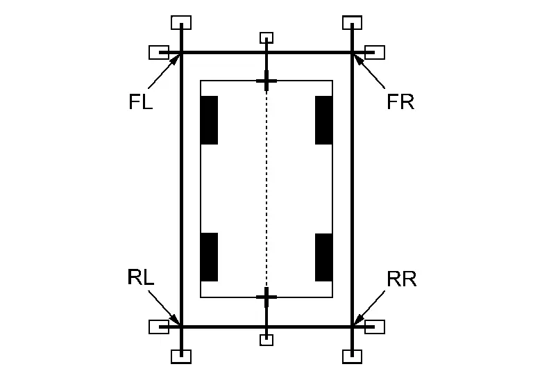
Hang a string with a weight as shown in the figure. Put the points FM0, RM0 (mark) on the ground at the center of the Nissan Pathfinder vehicle front end and rear end with white packing tape or a pen.

Thread 
Weight 
Point FM0 (mark) 
Point RM0 (mark) 
Packing tape (to fix the vinyl string) 
Vinyl string -
Route the vinyl string under the Nissan Pathfinder vehicle, and then pull and fix it on the point approximately 1.0 m (39.9 in) to the front and rear of the vehicle through the points FM0 and RM0 using packing tape.
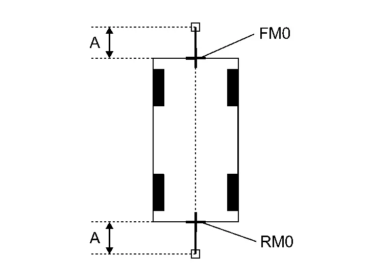
A : Approx.1.0 m (39.9 in) -
Put the points FM and RM (mark) 75 cm (29.5 in) from the points FM0 and RM0 individually.
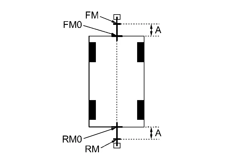
A : Approx. 75 cm (29.5 in) -
Route the vinyl string through the points FM and RM using a triangle scale, and then fix it at approximately 1.5 m (59.0 in) on both sides with packing tape.
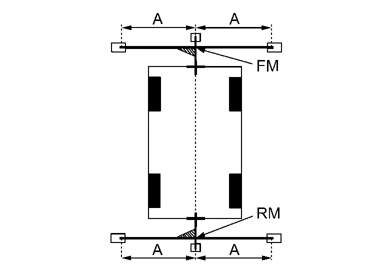
A Approx. 1.5 m (59.0 in) -
Put the points FL, FR, RL, and RR (mark) to both right and left [Nissan Pathfinder vehicle width / 2 + 30 cm (11.8 in)] from the points FM and RM.
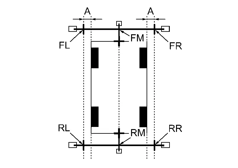
A : Approx. 30 cm (11.8 in) -
Draw the lines of the points FL – RL and FR – RR with vinyl string, and fix it with packing tape.
-
Put a mark on the center of each axle
 , draw vertical lines to the lines of the points FL – RL and FR – RR from the marks on the center of the axle using a triangle scale, and then fix the lines using packing tape.
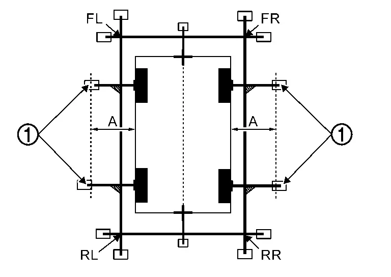
A : Approx. 60 cm (23.6 in)
Indication of “Incomplete calibration”>>
GO TO 4.
NO>>GO TO 5.
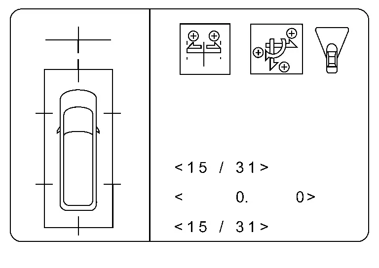
PERFORM “CALIBRATING CAMERA IMAGE”
 CONSULT
-
Select “CALIBRATING CAMERA IMAGE” in “Work Support” mode of “AVM”.
 NOTE:
NOTE:
In random order, perform the operation for all cameras for which un-match display
 appears.
-
Front camera: “CALIBRATING CAMERA IMAGE (FRONT CAMERA)”
-
Side camera RH: “CALIBRATING CAMERA IMAGE (PASS-SIDE CAMERA)”
-
Side camera LH: “CALIBRATING CAMERA IMAGE (DR-SIDE CAMERA)”
-
Rear camera: “CALIBRATING CAMERA IMAGE (REAR CAMERA)”
-
-
Perform “CALIBRATING CAMERA IMAGE” as per the following procedure.
-
On the adjustment screen of each camera, adjust the parameter by touching the “AXIS X”, “AXIS Y”, and “ROTATE” to place the calibration marker shown on the camera screen on the target line drawn on the ground.
-
On the adjustment screen of each camera, operate “+” and “-” of “Magnify/Reduce”, so that images on screen of target line and calibration maker are aligned.
-
-
Touch “APPLY” on the CONSULT screen. “Writing...” is displayed and adjustment results are shown on the camera screen.
CAUTION:
Check that “Writing...” is displayed. Do never perform other operations while “Writing...” is displayed.
-
Touch “OK” on the CONSULT screen. “PRCSNG” is displayed and adjustment results are written to the around view monitor control unit.
CAUTION:
Check that “PRCSNG” is displayed. Never perform other operations while “PRCSNG” is displayed.
>>
GO TO 5.
PERFORM “FINE TUNING OF BIRDS-EYE VIEW” (1)
 CONSULT
-
Select “FINE TUNING OF BIRDS-EYE VIEW” in “Work Support” mode of “AVM”.
-
Perform “FINE TURNING OF BIRDS-EYE VIEW” as per the following procedure.
CAUTION:
Perform adjustment operation slowly because approximately 1 second is required for changing image on screen.
 NOTE:
NOTE:
Touch “SELECT” on CONSULT screen and select camera position for adjustment.
-
Operate “+” and “–” of “AXIS X”, “AXIS Y”, and “ROTATE”, so that images on screen of target line on the ground and marker are aligned between each camera.
-
Operate “+” and “–” of “Magnify/Reduce”, so that images on screen of target line on the ground and marker are aligned between each camera.
-
-
Touch “APPLY” on the CONSULT screen. “Writing...” is displayed and adjustment results are shown on the camera screen.
CAUTION:
Check that “Writing...” is displayed. Do never perform other operations while “Writing...” is displayed.
-
Touch “OK” on the CONSULT screen. “PRCSNG” is displayed and adjustment results are written to the around view monitor control unit.
CAUTION:
-
Check that “PRCSNG” is displayed. Never perform other operations while “PRCSNG” is displayed.
-
After touching the “OK”, never touch screen other than the “BACK”.
-
 NOTE:
NOTE:
-
The adjustment value is cancelled in this mode by performing “Initialize Camera Image Calibration”.
Is the gap between the each camera image normal?
YES>>Work End.
NO>>GO TO 6.
PREPARATION OF TARGET LINE 2
Draw target line 2
 at the position of the approximately 1.0 m (39.9 in) outside from target line 1
 which established by procedure 2.
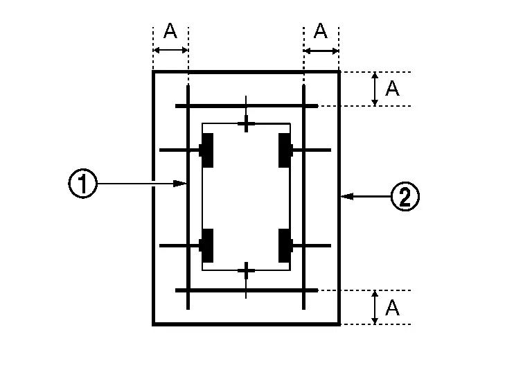
| A | : Approx.1.0 m (39.9 in) |
 NOTE:
NOTE:
The white lines far from the Nissan Pathfinder vehicle may not be aligned at the boundary of each camera image. The farther the line, the greater the difference is. can adjust it in detail by drawing a target line 2.
>>
GO TO 7.
“PERFORM “FINE TUNING OF BIRDS-EYE VIEW” (2)
 NOTE:
NOTE:
This adjustment merges the boundary line of each camera image which was not able to adjust by “FINE TUNING OF BIRDS-EYE VIEW” (1).
 CONSULT
-
Select “FINE TUNING OF BIRDS-EYE VIEW” in “Work Support” mode of “AVM”.
-
Perform “FINE TURNING OF BIRDS-EYE VIEW” as per the following procedure.
CAUTION:
Perform adjustment operation slowly because approximately 1 second is required for changing image on screen.
 NOTE:
NOTE:
Touch “SELECT” on CONSULT screen and select camera position for adjustment.
-
Confirm the gap of the boundary of target line 2 between the camera image and operate “+” and “–” of “AXIS X”, “AXIS Y”, “ROTATE” and “Magnify/Reduce”, and adjust the gap of the target line 2 boundary.
-
-
Touch “APPLY” on the CONSULT screen. “Writing...” is displayed and adjustment results are shown on the camera screen.
CAUTION:
Check that “Writing...” is displayed. Never perform other operations while “Writing...” is displayed.
-
Touch “OK” on the CONSULT screen. “PRCSNG” is displayed and adjustment results are written to the around view monitor control unit.
CAUTION:
-
Check that “PRCSNG” is displayed. Never perform other operations while “PRCSNG” is displayed.
-
After touching the “OK”, never touch screen other than the “BACK”.
-
 NOTE:
NOTE:
-
The adjustment value is cancelled in this mode by performing “Initialize Camera Image Calibration”.
>>
Work End.

Nissan Pathfinder (R53) 2022-2026 Service Manual
Basic Inspection
- Diagnosis and Repair Workflow
- Additional Service When Replacing Around View Monitor Control Unit
- Mac Key Writing
- Configuration (around View Monitor Control Unit)
- Writing of Calibration Data
- Calibrating Camera Image (intelligent Around View Monitor)
Contact Us
Nissan Pathfinder Info Center
Email: info@nipathfinder.com
Phone: +1 (800) 123-4567
Address: 123 Pathfinder Blvd, Nashville, TN 37214, USA
Working Hours: Mon–Fri, 9:00 AM – 5:00 PM (EST)
